ATTENTION
Be sure to observe the following, as they may well become causes for fire,
electric-shock, injuries, and damage to parts.
- Be sure to unplug power source before engaged in disassembly, installation,
adjustment.
- In case of installing please pay special care to clamp electrical cords, etc., scars
to sheath, mis-circuit, etc.
- Be sure to use regular standard part in replacing.
CONTENTS
1. Products specification
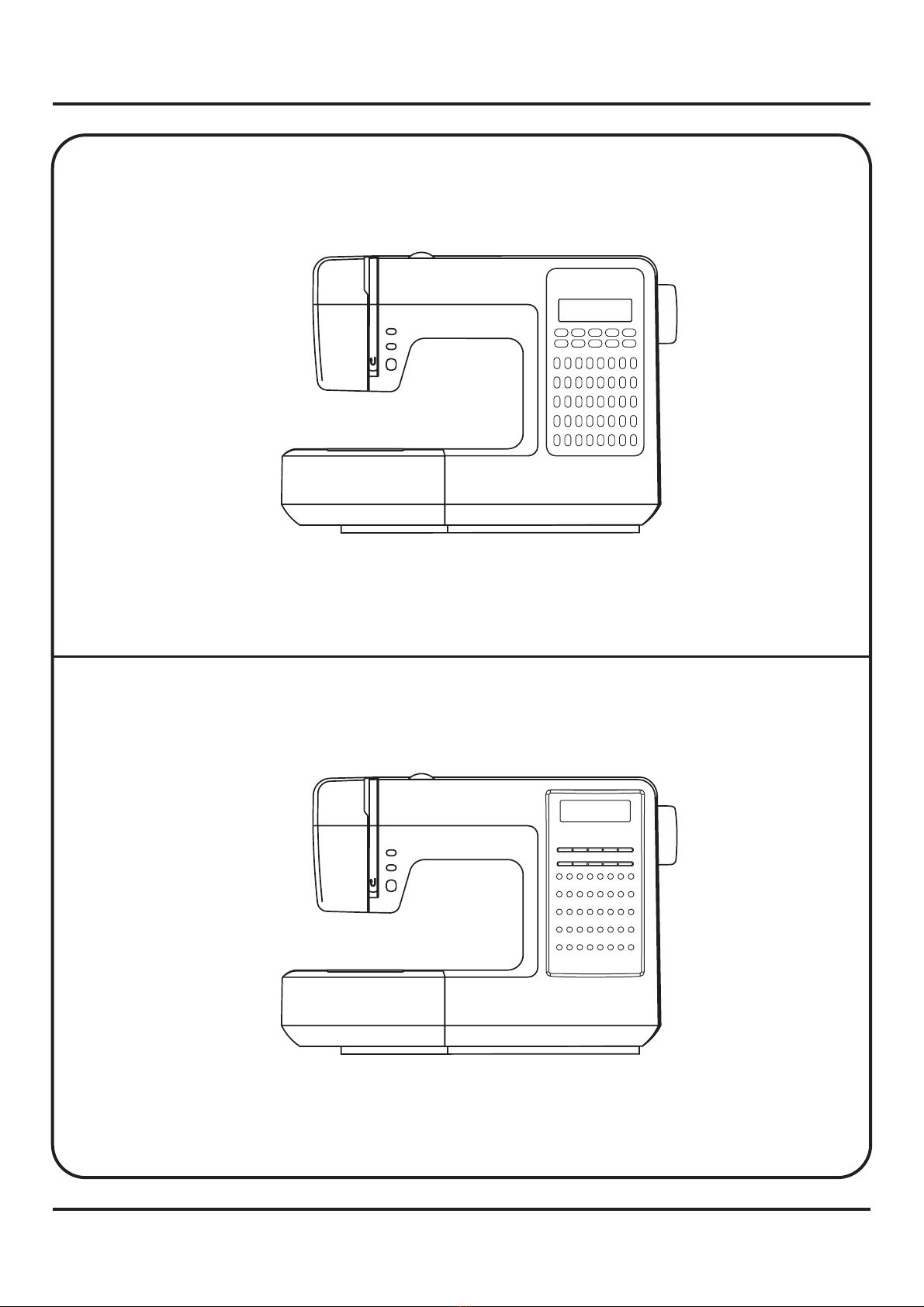
2. Out look
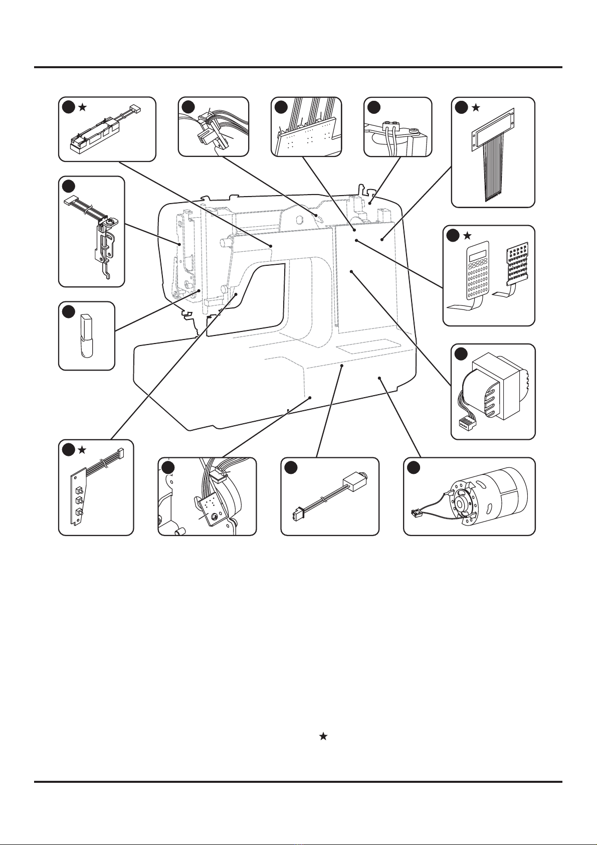
3. Names of principal parts
5. Removing methods of external parts
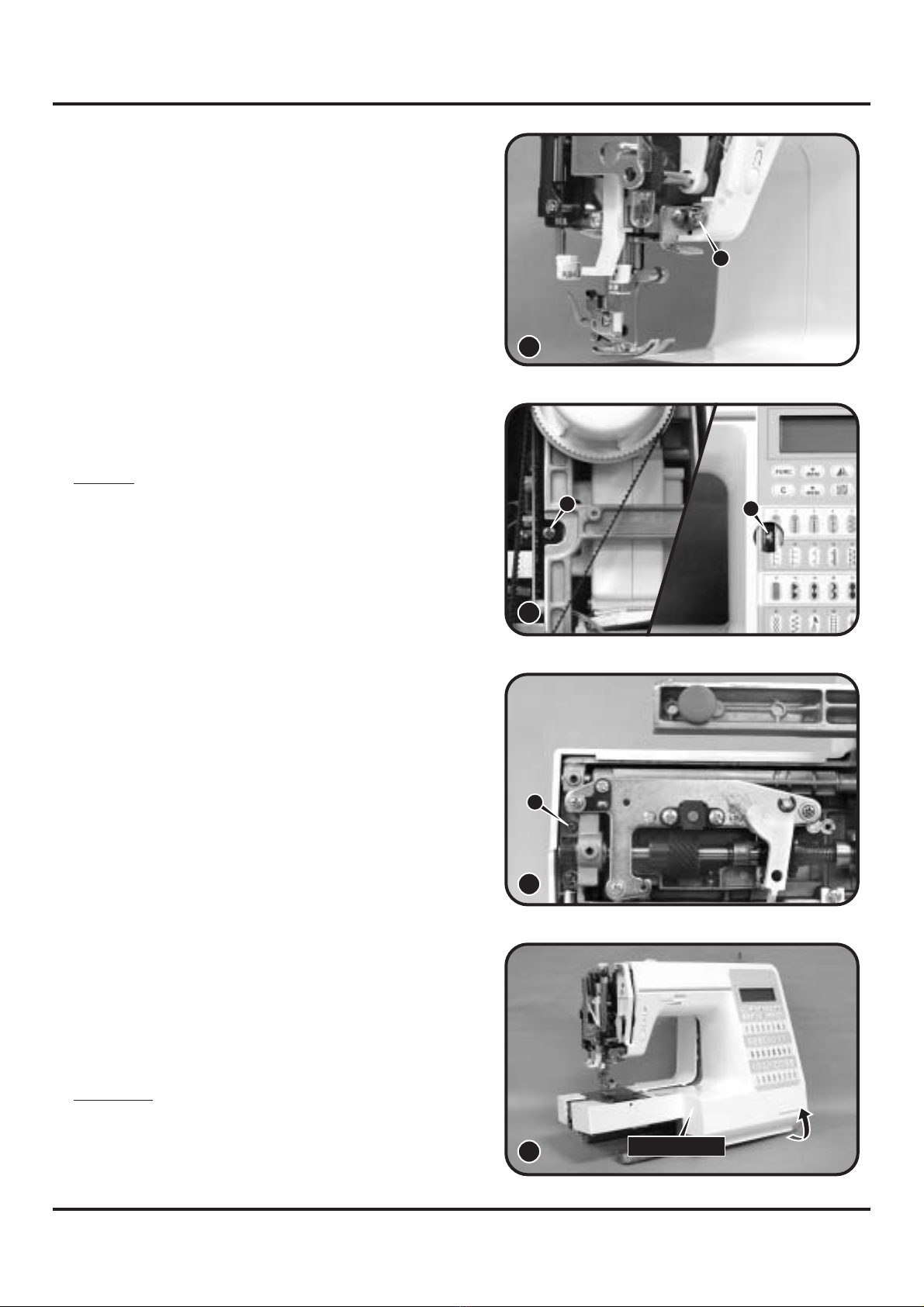
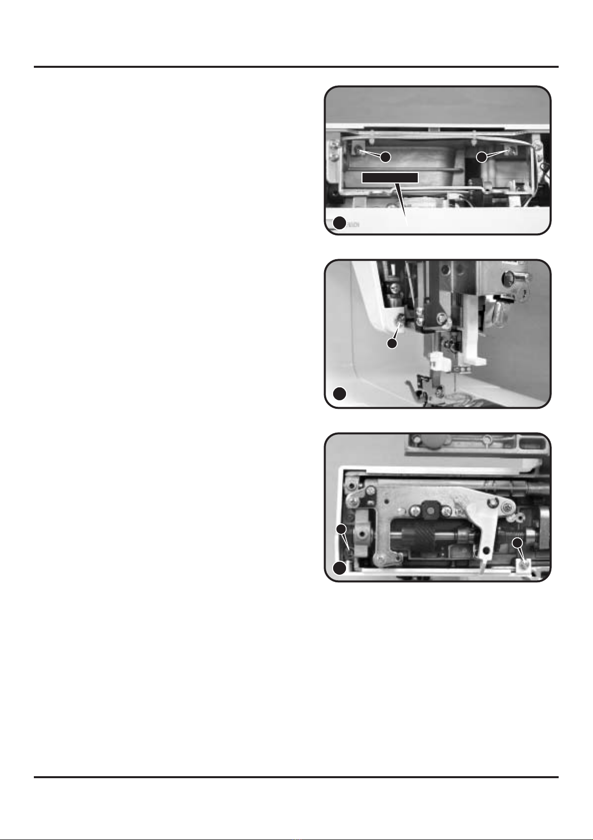
6. Adjusting methods of each part
.............................................................................................2
.....................................................................................................................3
..........................................................................................4
5.1 Face plate..........................................................................................................6
5.2 Arm top cover ....................................................................................................6
5.3 Sewing table complete ......................................................................................6
5.4 Cord reel cover ..................................................................................................6
5.5 Belt cover...........................................................................................................7
5.6 Free arm cover ..................................................................................................7
5.7 Free arm foot bush ............................................................................................7
5.8 Front cover .....................................................................................................7-8
5.9 Back cover.........................................................................................................9
6
6
4. Names of electronic parts
7. Trouble shooting of electrical parts
8. Circuit diagram
........................................................................................5
.1 Symbol instructions .........................................................................................10
.2 Play of arm shaft..............................................................................................11
6.3 Drop middle point of needle.............................................................................11
6.4 Height of presser foot ......................................................................................12
6.5 Needle flow at maximum zigzag width ............................................................13
6.6 Drop middle point of needle.............................................................................14
6.7 Needle position of zigzag ................................................................................15
6.8 Automatic needle threader adjustment............................................................16
6.9 Adjustment of feed rock shaft and feed lifting rock cam ..................................17
6.10 Height of needle bar ........................................................................................18
6.11 Timing of needle and hook ..............................................................................19
6.12 Distance-needle-hook......................................................................................20
6.13 Play between shuttle driver shaft gear and lower shaft gear...........................21
6.14 Play of shuttle driver shaft ...............................................................................22
6.15 Feed-dog height ..............................................................................................23
6.16 Position of feed-dog in relation to the needle plate (left to right) .....................24
6.17 Upper thread tension adjustment ....................................................................25
6.18 Shuttle hook tension adjustment .....................................................................26
6.19 Motor belt tension ............................................................................................27
6.20 Drop point of needle ........................................................................................28
6.21 Adjustment of BH.............................................................................................29
6.22 Bobbin winding problem ..................................................................................30
6.23 Replace the fuse..............................................................................................31
.................................................................32-35
..................................................................................................36-41
1