Astrapool Dual Pure 40 User manual

ENGLISH
1 Número de revisión Rev 001-2013-08-06
SOMMAIRE –CONTENTS –SUMARIO –SOMMARIO
SUMARIO –INHALTSVERZEICHNIS
TECHNICAL SPECIFICATIONS AND GENERAL INFORMATION .................................................................. 2
INSTALLATION IN THE TECHNICAL AREA................................................................................................. 3
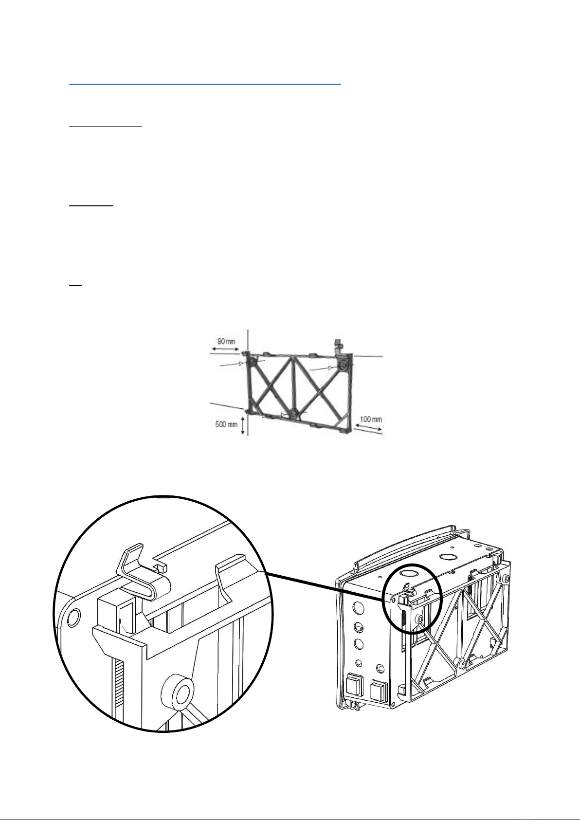
INSTALLATION OF THE CHAMBER: .......................................................................................................... 4
PROBE:..................................................................................................................................................... 5
FLOW SWITCH: ........................................................................................................................................ 5
INSTALLATION OF THE EARTH ELECTRODE: ............................................................................................ 6
ELECTRICAL CONNECTIONS: .................................................................................................................... 7
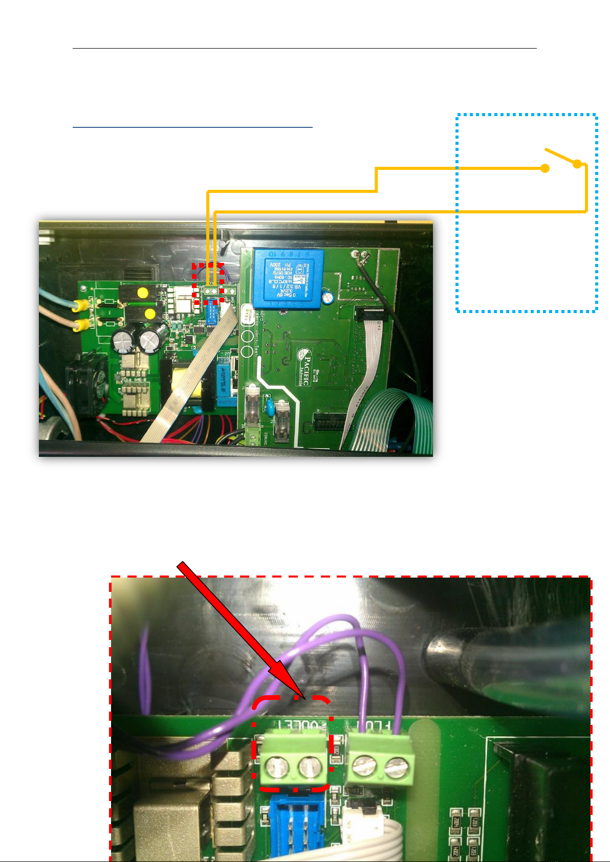
SERVO-CONTROLLED BY THE COVER....................................................................................................... 8
OPERATING THE ELECTROLYSER.............................................................................................................. 9
RECOMMENDATIONS............................................................................................................................ 10
SWITCHING ON THE ELECTROLYSER...................................................................................................... 10
ADJUSTING CHLORINE PRODUCTION.................................................................................................... 11
CHLORINE ANALYSIS METHOD .............................................................................................................. 11
INDOOR POOL OR POOLS WITH COVERS .............................................................................................. 11
ADJUSTING THE DURATION OF THE POLARITY INVERSION .................................................................. 12
CHECKS AND MAINTENANCE ................................................................................................................ 12
NON-MODIFIABLE PARAMETERS: ......................................................................................................... 13
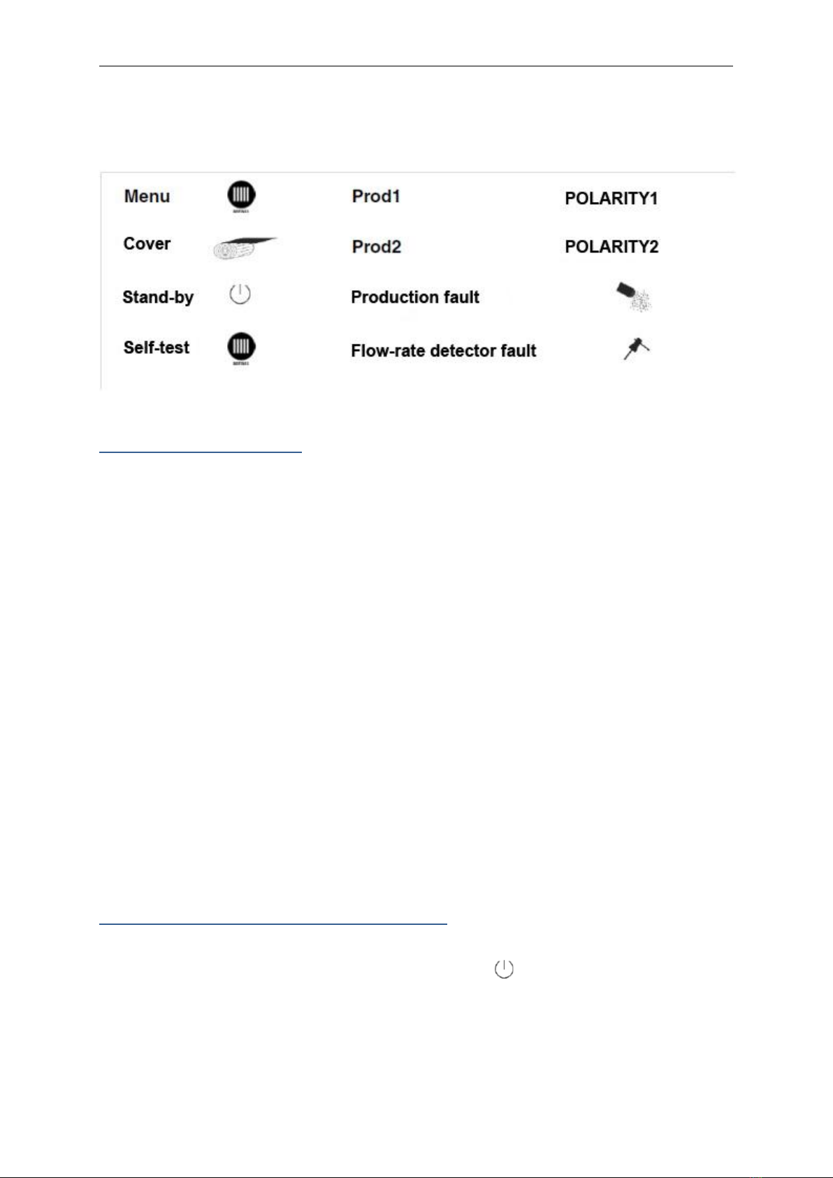
INDICATORS........................................................................................................................................... 15
pH REGULATION .................................................................................................................................... 16
SWITCHING ON FOR THE FIRST TIME.................................................................................................... 17
TIPS FOR THE CORRECT USE OF THE pH REGULATOR........................................................................... 18
TAYLOR SCALE ....................................................................................................................................... 19
WARRANTY............................................................................................................................................ 19

ENGLISH
2 Número de revisión Rev 001-2013-08-06
TECHNICAL SPECIFICATIONS AND GENERAL INFORMATION
Unit:
-Power supply (servo-controlled by the filtration pump) 220 Volts 50/60 Hz
-Weight 3050 g.
-Dimensions 38 x 27.5x 16
-CE Marking yes
-Degree of protection IP X5
Electrolyser Use:
-Recommended salt level 4g/l
-Minimum salt level 3.2g/l
-Recommended pH 7.4
-Recommended stabiliser 10 à 15 g/m3
-Maximum stabiliser 40g/m3
-Minimum operating time per day consult the
recommendations
provided by the
manufacturer of your
filtration system
-Water temperature > 18°C
pH Use:
-Measurement range 4 to 11 pH
-Programmable control range 6 to 9 pH
-Control mode pH + or pH –
-Type of control proportional
-Accuracy +/-0.02 pH
-Resolution 0.001 pH
-Operational range of the proportional control +/-0.5 pH
-Flow pump 2.4 l/h
-Maximum acceptable pressure 1 bar
-Plastic probe with solid gel
-pH probe connection cable 5 m
-Dimensions of the pH probe L x Ø 120x12mm

ENGLISH
3 Número de revisión Rev 001-2013-08-06
INSTALLATION IN THE TECHNICAL AREA
Electronic unit:
-Fix the support for the unit onto a wall using the provided screws and fasteners. If possible,
this should be close to the filtration unit to facilitate electrical connection and be protected
from water spray and condensation.
Important: ensure that the controls for the unit are accessible. To prime the pH pump correctly, it is
important that the height between the suction line and the pH pump head do not exceed 2 metres.
-Attach the wall support, respecting the edges below (in mm). They indicate the compulsory
minimum spacing between the support and other elements on the wall.
NB: screws and fasteners to fix the device are provided. Holes of a diameter of 8mm should be made.
-Place the device on the support.
Verify the correct positioning of the non-return clip

ENGLISH
4 Número de revisión Rev 001-2013-08-06
INSTALLATION OF THE CHAMBER:
Attach the chamber to the return pipe that runs towards the swimming pool, after the filter and after
the heater or the beginning of the compressor.
The water must circulate from the T-pipe towards the part where the pipe narrows (follow the
direction of the arrow on the chamber); the water flow must circulate between the plates
(electrodes). Make sure that there is enough space on the removable side of the chamber to be able
to withdraw the electrode.
If the chamber is mounted on the bypass, ensure that a minimum of 80% of the flow passes through
the latter.
SALT ELECTRODE
FLOW
pH PROBE
EARTH
pH INJECTION
FLOW SWITCH
FLOW
Main drain
Filter
Pump
By-Pass
Dual pure
Reagent Tank
Chamber
Return to pool
Drain
By-Pass
Heater or
other

ENGLISH
5 Número de revisión Rev 001-2013-08-06
PROBE:
Place the pH probe on the salt chlorinator chamber in the space provided.
Important: ensure that the probe is placed so that the two protective edges of the glass ball are
perpendicular to the flow.
FLOW SWITCH:
We advise the installation of the flow switch in the following cases
-Filtration pump situated above the water level (risk of un-priming).
-Chamber installed in a bypass configuration.
Installation: Install the flow switch in the place on the chamber designed for the purpose and
position the arrow above it in the direction of the water flow.
Operating principle: If the flow is interrupted accidentally or during a backwash and whenever the
water flow-rate is less than 2.9 m3/h, the flow switch will cut chlorine production.
Warning:
-The flow switch provided contains its own system of recognition. If you need to replace it,
contact your specialised dealer.
-If the flow switch is not plugged in, the device will work normally, regardless of the presence
of hydraulic flow. It is, therefore, absolutely necessary for the unit to be controlled by the
filtration pump in order to ensure that water is circulating when chlorine is being produced
and pH correctors injected.
FLOW
pH PROBE
pH Injection
Earth
Flow switch
Salt electrode
FLUX
FLOW
Arrow in the
direction of
flow

ENGLISH
6 Número de revisión Rev 001-2013-08-06
INSTALLATION OF THE EARTH ELECTRODE:
We recommend the installation of this electrode in order to measure the residual currents present in
the water.
Mounting the earth electrode:
Mount the earth electrode in the place on the chamber designed for this purpose.
Put the earth pin in place.
Connect the earth electrode to the pin with a braid of 16mm2minimum.
NEVER USE AN EXISTING ELECTRICAL EARTH.
Reagent tank:
It is preferable to use liquid pH+ or pH- reagents as the case may be. We strongly advise against using
pH correctors in powder form or hydrochloric acid.
Place the reagent tank near to the control box and, if possible, avoid placing it directly underneath.
The end of the suction pipe with its suction strainer should be located approximately 2 cm above the
bottom of the tank.
Injection:
Place the injector rod on the salt chlorinator chamber in the dedicated housing.
Earthing 20 mm
Main drain
Filter
Pump
By-Pass
Dual pure
Reagent Tank
Chamber
Return to pool
Drain
To independent earth
pin
By-Pass
Heater or
other

ENGLISH
7 Número de revisión Rev 001-2013-08-06
ELECTRICAL CONNECTIONS:
-The powder supply to the unit: The system works in parallel with the filtration pump. It is
imperative that it functions at the same time as the filtration.
The connection is made via the contactors on the filtration pump in the filtration unit. A unit
that is permanently connected will lose its warranty.
Diagram of an electrical connection (example only):
-The power of the salt electrode: connect the cable supplied for this purpose. The connection
may be made in either direction. Tighten the screws correctly. A badly tightened connection
will result in overheating.
-Probe connection cable: Connect the BNC plug of the cable to the socket located below the
system.
-Flow Switch: connect the cable to the socket located under the system.
Override
Contactor
Clock
4A-AM
Circuit breaker
Automatic
Pump
Mono 220 V
1 3 5
2 4 6
1 3 5 I3 A1
2 4 6 I4 A2
A.

ENGLISH
8 Número de revisión Rev 001-2013-08-06
SERVO-CONTROLLED BY THE COVER
Cover panel
View of the interior of the device.
Servo-controlled connection to the cover
To the cover panel
connection
Closed cover = Closed
connection

ENGLISH
9 Número de revisión Rev 001-2013-08-06
OPERATING THE ELECTROLYSER

ENGLISH
10 Número de revisión Rev 001-2013-08-06
RECOMMENDATIONS
Please respect the following values in the order to ensure the proper operation of this electrolyser:
Salt rate: Recommended: 4 g/l
Minimum: 3.2g/l
pH: Recommended : less than 7.8
Stabilizer: Recommended: 10 à 15 g/m3
Maximum: 40g/m3
Minimum daily operating
time: respect the recommendations of the
manufacturer of your filtration system.
Water temperature: do not use below 18°C.
Connection: 220 volts –50/60 Hz must be connected
to the filtration pump.
SWITCHING ON THE ELECTROLYSER
Ensure that the salt content is correct.
Place the switch to « on »: the fan will start, the “stand-by » indicator will light up, followed by
"Prod1" and finally the ampere display. The electrode will turn on automatically after a period of
time.

ENGLISH
11 Número de revisión Rev 001-2013-08-06
ADJUSTING CHLORINE PRODUCTION
Starting-up for the first time:
a) Put filtration in manual mode (24h filtration) then press the key up to 100%, the time
necessary to obtain the desired level of chlorine (for a private swimming pool, chlorine-free
is between 0.5 and 2ppm).
b) Switch the filtration to automatic and check the chlorine content regularly.
c) Adjust production by using or if the desired rate is too low or two high.
d) Add chlorine products manually if it takes more than 48 hours to fill the pool.
Where there is a cover, setting the production of your electrolyser is carried out when the swimming
pool is open.
CHLORINE ANALYSIS METHOD
The analysis should be made at approximately the same time and the same place (at a point
equidistant between the backflow and the skimmer). The chlorine produced by your salt chlorinator
is very volatile and the reading of its content may vary according to different parameters (UV,
number of bathers, organic matter, etc.). If there is an exceptionally high number of bathers, then we
advise you to switch the filtration to manual mode in order to compensate for chlorine deficit caused
by this excessive number of bathers.
INDOOR POOL OR POOLS WITH COVERS
If swimming pool water is not exposed to UV rays, then the chlorine content may become excessive
and therefore corrosive. It is recommended adjusting the production of your electrolyser when the
cover is open or closed.
If the electrolyser is servo-controlled through the connection to the cover, the production of chlorine
will be divided by 2, with the cover closed (E.g.: 50 % de production = open cover, and 50% / 2 = 25%
de production = closed cover).
The factory setting is 50%. In order to change this, proceed as follows:
Switch off the device
-Press and simultaneously while switching on the device.
-Keep and pressed until the screen displays ATT then PRO. Press twice on and FE
appears.
-Press Menu to Confirm.
-The screen displays a production-time setting for a closed cover.
-Press or to change the production setting when the cover is closed.
-Press Menu to Confirm.

ENGLISH
12 Número de revisión Rev 001-2013-08-06
ADJUSTING THE DURATION OF THE POLARITY INVERSION
Your salt chlorinator was programmed in the factory for a polarity change every 4 hours.
According to the hardness of the water (TH for degree of Total Hardness), it is possible to change this
cycle from 1 to 99 hours.
Switch off the device
-Press and simultaneously while switching on the device.
-Keep and pressed until the screen displays ATT then PRO.
-Press Menu, DUR appears.
-Press Menu, the duration of the polarity inversion is displayed; press or to change the
value.
-Press Menu to confirm
SELF TEST:
Warning! Water temperature > 23°C, minimum salt content 4g/l.
This function allows one to check the state of the electrode and that the unit is working properly.
Press the "TEST" key.
The LEDs light up,
Then "prod 1" followed by "prod2".
If all of the LEDs flicker after 30 seconds, then the test is OK.
CHECKS AND MAINTENANCE
CHECK THE PARAMETERS:
Press "MENU" for two seconds,
Scroll through the functions using or ,
Then press "Menu" to visualise:
-DUR duration of the polarity inversion (self-cleaning expressed in hours).
Factory setting: 4
-FE: regulates production according to the position of the cover.
Percentage of production depends on the cover being in the closed position.
Factory setting: 50%
-INT: intensity sent to the electrode (expressed in amperes).

ENGLISH
13 Número de revisión Rev 001-2013-08-06
-DEF: settings, that is :
-DUR: 4 h
-FE: 50%
-PROD: 55%
-TPS: accumulated production time
-TEN: electrode operating voltage
NON-MODIFIABLE PARAMETERS:
Device switched on:
-Press Menu once and DUR appears
(DUR = Duration of polarity inversion)
-Press Menu: the screen displays 4 heures (factory setting)
-Press Menuto exit: the setting amperage appears
-Press Menu: DUR appears
-Press FE appears (FE= opening/closing of the cover)
-Press Menu: production time appears, 50% factory setting 0.50)
-Press Menu to exit: the setting amperage appears
-Press Menu: DUR appears
-Press twice INT appears (INT= intensity)
-Press Menu: the amperage is displayed
-Press Menu to exit: the setting amperage appears
-Press Menu: DUR appears
-Press 3 times TPS appears (TPS = tens of hours)
-Press Menu: a number of tens of hours appears
-Press Menu to exit: the setting amperage appears
-Press Menu: DUR appears
-Press 4 times TEN appears (TEN = voltage)
-Press Menu: the voltage is displayed
-Press Menu to exit: the setting amperage appears
-Press Menu: DUR appears
-Press 5 times TEP appears (TEP = temperature of the device)
-Press Menu: the temperature of the device is displayed
-Press Menu to exit: the setting amperage appears
If, for any of the possible displays listed above, you do not press the Menu button, then the device
will automatically reset to amperes after one minute.

ENGLISH
14 Número de revisión Rev 001-2013-08-06
To find a specific program:
Use the drop-down Menu:
-Press Menu: DUR appears
-Press until the desired program is displayed.
Add salt:
Check the salt content. If the concentration is less than 4 g/l, add salt according to the following
formula:
Q = (4-T) x V Q = quantity of salt to be added in Kg
4 = salt content to be respected
T = measured salt content in the pool
V = volume of the pool in m3
Always stop the device before adding salt directly to the pool.
Wait for the salt to dissolve before turning the salt chlorinator on again.
Adding chemical products:
Always stop the device before adding chemical products directly to the pool. Wait for the chemical
products to dissolve before turning the salt chlorinator on again.
Presence of hydrogen peroxide: This product cancels the chlorine reading for approximately 3 weeks.
The sterilizer produced by your chlorinator is compatible with most swimming-pool water treatment
products, with the exception of those containing PHMB polymers. In all cases, stop the chlorinator
while you add products and until they have been completely dissolved.
Winter months:
If the filtration of the pool is maintained during the winter months, we recommend turning the
chlorinator off when the temperature falls below 15°C.
Encrusted electrode:
The electrode must have a clean appearance without limescale encrustations. If need be, de-scale
the electrode by placing it in a solution containing 80% water and 20% chlorhydric acid. Then check
why the electrode got encrusted:
Salt concentration too low
Polarity inversion time is too long
Electrode wearing out (see following paragraph)
Unit inversion fault
Upon immersion of the electrode for scaling, do immerse further than the resin!

ENGLISH
15 Número de revisión Rev 001-2013-08-06
Checking the state of the electrode:
The voltage can be measured at both terminals of the electrode; it must be approximately 9 volts.
Measure it in the DC position, with a salt content of 4g/litre, a water temperature of more than 15°C
and an electrode without calcareous encrustation.
If the voltage is more than 10.5 Volts, then the electrode is worn out and should be replaced
quickly.
Reminder: each kind of electrode receives a specific current indicated on the left-hand sticker.
Example: for a salt chlorinator 60 : 8.5 ampères.
A current of more than one amperes less that indicated signifies a problem either with the salt , the
electrode itself, the water temperature or limescale encrustation.
Cleaning the pool drainage filter:
Stop the chlorinator during any handling of the filter’s six-way valve : cleaning, rinsing, draining, etc.
INDICATORS
Flow switch fault:
When this indicator is lit all production is halted: this means that the flow switch is badly positioned,
faulty or else the flow through the chamber is non-existent or insufficient.
Production fault:
When the electrode produces less than 75% of its capacity, the indicator lights up without stopping
the operation of the chlorinator:
-The salt content is insufficient
-The water temperature required the device to stop
-The electrode is encrusted with limescale (see paragraph on limescale encrusted electrode)
-The electrode is weakening and should be replaced soon
(see paragraph about limescale encrusted electrode)
Stand-by:
The device has finished its production cycle according to the percentage that you have indicated
using or ; it is waiting for the end of the cycle (100%) so that it can re-start on the other
polarity.

ENGLISH
16 Número de revisión Rev 001-2013-08-06
Cover :
The indicator lights up when the cover is detected as closed. For it to be possible to detect this,
please connect the dry connection on the card to the connector provided for this purpose when
installing a cover. (See page 8/19 Servo-controlled Cover)
pH REGULATION
The pH (Potential Hydrogen) value indicates acidity or alkalinity of water. A balanced pH improves
the efficiency of water treatment products and enhances user comfort.
Recommended pH: 6.8 –7.4 (see Taylor Diagram)
Recommended CAT: 6 à 25°F (see CAT alkalinity)

ENGLISH
17 Número de revisión Rev 001-2013-08-06
SWITCHING ON FOR THE FIRST TIME
-Calibration:
Switch on the device, wait until the reading stabilises and indicates the pH value of the water.
Measure the pH of the swimming pool water, read the pH on the device and adjust it, pressing
and , to the precise value measured.
The device is calibrated and ready to work. The indication given by the pH probe can vary over time.
We, therefore, advise you to re-do this at least once a year. A timer allows the pump to start after
approximately 3 minutes.
When the pump is in operation, the green light comes on.
-Setting the set point:
The factory set point is 7.4.
When the device is on, press the SET button, and a value will be displayed. Hold down the SET button
and use the and keys to adjust the desired set point (between 6.2 and 8.6). It is
recommended between 7.0 and 7.4
-Injection time:
New devices are programmed for an injection time of 2 hours per filtration cycle.
Other injection times are possible (1 or 4 hours per day).
Selecting the injection time: when switching on the device, the maximum dosage time is displayed 2
seconds after displaying the product type.
Depending on the swimming pool volume, if the injection time needs to be modified, slide the
jumper on the electronic board to the right. This operation must be carried out by a professional.
The indicator lights on to inform an injection error :
oLack of pH corrector or
oThe pH setpoint has not been reached within the programmed injection duration.
-Set to zero:
Switch off the device, disconnect the probe and switch the device on again.
Simultaneously press on the keys , and SET for 3 seconds, and the device will indicate rA2.
This re-set to zero makes it possible to re-establish a standard calibration value and to re-start at an
established set point of 7.4.
-Regulation:
Regulation takes place when the pH is above or below +/- 0.03 pH of the set point (e.g. if the set
point is 7.4, the pump will automatically start when the pH is higher than 7.43 and will stop when the
pH reaches 7.37).

ENGLISH
18 Número de revisión Rev 001-2013-08-06
TIPS FOR THE CORRECT USE OF THE pH REGULATOR
-Washing the filter - Adding product:
It is important to turn the device off when handling the filter (draining, washing, rinsing), and when
adding products manually (CAT, pH -, pH+, stabiliser, etc.)
-CAT –Alkalinity:
The CAT must be between 6 and 25 French degrees.
Low mineralised water (lower than 8°F) reacts suddenly to each pH modification: the water loses its
‘buffering’ capacity.
The result can be extensive pH variations.
E.g.: slightly acidic rainfall can cause the pH to drop below the recommended value.
To better manage pH, we advise testing the CAT value of the water once a year using the test kit, and
rectifying it if incorrect, by adding the right products.
This operation, called CAT calibration, should be repeated at the beginning of each season.
To find out the ideal CAT value, see the Taylor Scale below.
-Peristaltic pump:
Grease the latex tube at the start of each season to maintain its elasticity.
To do this: unscrew the 2 small screws of the transparent cover, apply a little silicone grease between
the rollers and the latex.
-Preparing for winter or emptying the swimming pool:
oPreparing for winter without emptying the piping: leave the pH probe in place
oPreparing for winter by emptying the piping: remove the pH probe, and place its cap
on it. This cap should be filled with a potassium chloride solution (KCl) in order to
hydrate the glass cell of the probe (if not, use swimming pool water). Store the probe
in a dry place with a constant temperature. Never leave the pH probe in the open air.
-Error signals:
Problems: if the device injects product for a longer time than the maximum dosage time, the alarm
lights up and product injection is no longer possible. Setting the injection time to zero can only be
done if the power supply has been switched off.
The device can measure pH values between 2.0 and 12.0.

ENGLISH
19 Número de revisión Rev 001-2013-08-06
Calibration of the pH probe can be conducted with a pH value between 6.2 and 8.6. If the value of
the pH measured by the probe is lower than 6.2 or higher than 8.6, the alarm lights up and
product injection ceases.
Solutions:
e) To bring the pH back to the correct value, check the product concentration in the container.
f) Check calibration of the probe
g) If the probe indicates a value higher than 11, it is defective
h) Have the condition of the probe checked
i) To delete the error message, switch the device off and then on again.
TAYLOR SCALE
WARRANTY
The unit is covered by a 2-year warranty against manufacturing defects as from the date of delivery.
If, during this period, repair of the unit or replacement of certain parts should be necessary, unless
such is due to negligence or an error attributable to the user while handling the equipment, return
the unit carriage paid.
The manufacturer shall return the goods in the same way.
The following are not covered by the warranty:
-If the pH pump has been operated with a non-conform product such as HCL acid
-If the probe has been subjected to poor winter storage conditions or has been broken by
handling or flow
-Lightning
-Electrical overvoltage
-Flooding
-Normal wear & tear of the probe

ENGLISH
20 Número de revisión Rev 001-2013-08-06
pH probe
pH probe life depends on :
-Whether the pool has been properly protected over the winter months: the probe must
never be left exposed to the air.
-Whether the probe has been properly stored over the winter months: replace cap over it
with KCL at constant temperature or with water from the pool in a frost-free area.
-How it has been handled: the glass ball is fragile.
-Whether the pH unit was switched off during backwashes.
In such specific conditions of use, we are unable to warranty pH probes beyond 6 months use.
This manual suits for next models
3
Table of contents
Other Astrapool Lighting Equipment manuals