VG-FL470A 470W Follow Spot Light User Manual VG-FL470A 470W Follow Spot Light User Manual
warning:It must be power off before cleaning
or maintenance of the light.
power cable will not be scratched by anything sharp.
5. Please cut off power when doesn't use or before cleaning, maintenance the light.
6. The light doesn't include any spare parts for repair. In order to avoid danger, please do
not open and change the product structure by yourself.
4. Cleaning & Maintenance
Clean the product frequently, it can keep the output brightness and extend the
product life
Product cleaning
Clean the output acrylic board and product body every 2 weeks, or smoke dust
accumulation will weaken the brightness of the light.
Use soft cloth with water to clean , do not with organic solvent ,such as ethyl alcohol
Clean the cool fan each month
Product maintenance
Product maintenance must consider the below terms.
All screws mounted on the lamp must reliably tightened, check and replace the corroded
screws.
Ensure fixed point for installation without any deformation
Check if the power cable is damage, and if the insulation layer is wear down.
To ensure good connection of the various parts of the circuit, and to avoid unnecessary
accidents coursed by bad electrical connections, the detailed inspection of the light must be
make by the authorized electrical engineer every three months.
5. Technology Parameters
Power supply:AC100-240V,50Hz-60Hz
Power consumption:550W
Light source:HRI 440W
Color temperature:built-in 7500K,6500K,4500K,3200K
Beam angle:5-9°
Control mode:manual control panel, DMX-512
DMX channels:7CHS
Dimmer:dual patches dimming
iris: linear zoom in & zoom out
Working environment:up to 40°C
Protection rate:IP20
Cover:A3+AL
Dimension: 8300x 310 x 270 mm
Packing size: 850 x500 x 490 mm (flight case)
N.W: 11.5kg
G.W: 38kg (flight case and stand)
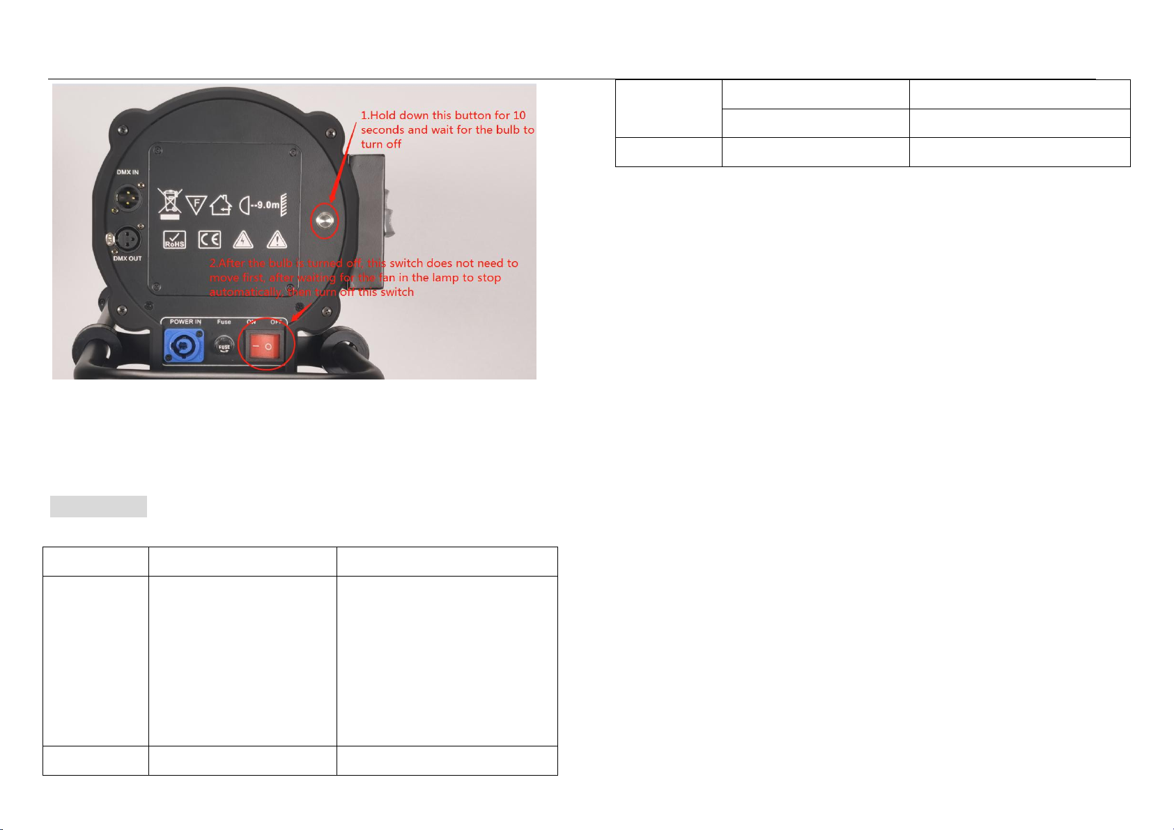
6.operation method
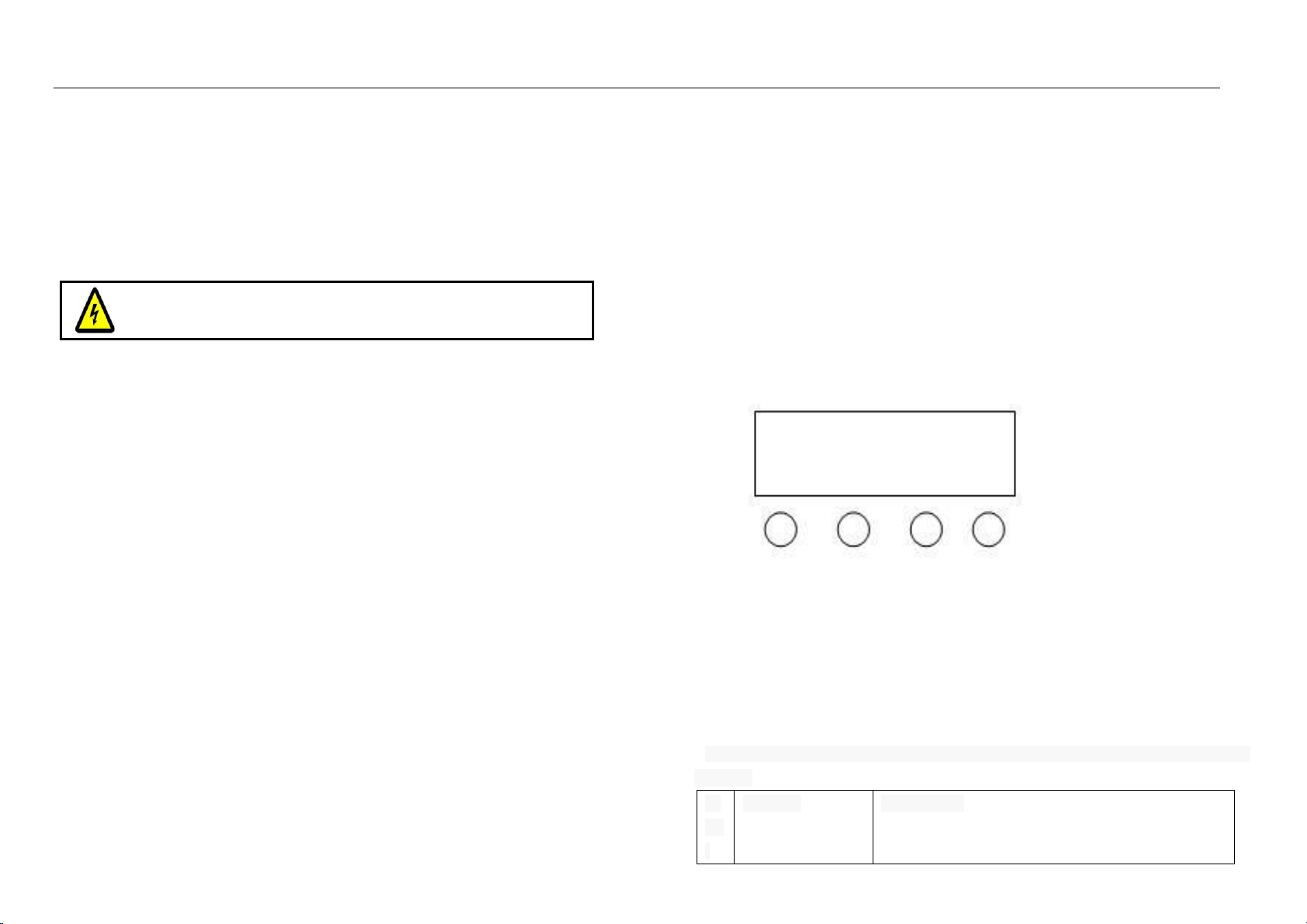
3.1 panel
A.The function keys
B.add key
C.Reduction key
D.Identify key
E.LED display
A B C D
Operation note: A will loop through six different functions, and the first two digits of the
digital tube represent the current function (refer to the function table). The last two
Numbers represent the location of the function. The address code. Or the speed, the
parameter. The parameter values can be modified by a B or C key. Press the D button to
confirm.
7.LED display window function table. (all functions are confirmed by D key when
selected)