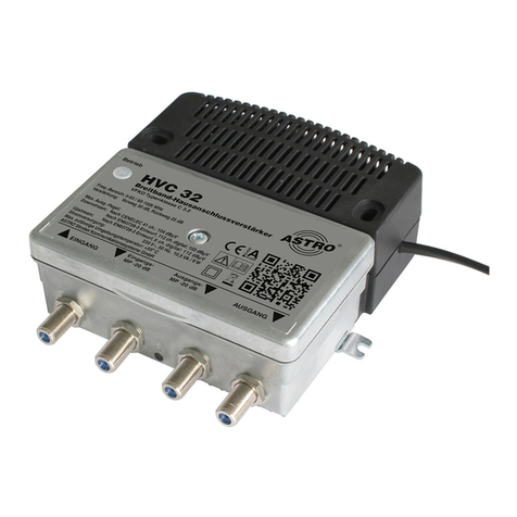
ASTRO HVB 21 User manual

Version 01-2021A

Before operating the device
OperatingmanualHVB21,HVB 31 a.HVB32 - Version01-2021Apage 2
Before operating the device
NOTE: Read this operating manual through carefully!It
contains important information about installation, ambient
conditions and maintenance of the device. Keep this operating
manual for future use and for handover in the event of a
change of owner or operator. A PDF version of this manual can
be downloaded on the ASTRO website (there may be a more
recent version).
The ASTRO company confirms that the information in this
manual was correct at the time of printing, but it reserves the
right to make changes to the specifications, the operation of the
device and the operating manual without prior notice.

page 3
Contents
OperatingmanualHVB21,HVB31 a.HVB32-Version 01-2021A
Contents
Symbols and conventions used...........................................page 04
Intended use........................................................................page 05
Intended audience for this manual.......................................page 05
Device description...............................................................page 06
Important safety information................................................page 08
Warranty conditions.............................................................page 12
Performance description......................................................page 12
Disposal...............................................................................page 12
Installation...........................................................................page 13
Connection and start-up......................................................page 14
Configuration.......................................................................page 14
Troubleshooting...................................................................page 16
Maintenance and repair.......................................................page 16
Block diagram......................................................................page 17
Technical data.....................................................................page 18

Symbols and conventions used
OperatingmanualHVB21,HVB 31 a.HVB32 - Version01-2021Apage 4
Symbols and conventions used
Symbols used in this manual
Pictograms are visual symbols with specific meanings. You will
encounter the following pictograms in this installation and operating
manual:
Warning about situations in which electrical voltage and non-obser-
vance of the instructions in this manual pose a risk of fatal injuries.
Warning about various dangers to health, the environment and
material.
Warning about thermal dangers due to hot surfaces.
Recycling symbol: indicates components or packaging materials
which can be recycled (cardboard, inserts, plastic film and bags).
Used batteries must be disposed of at approved recycling points.
Batteries must be completely discharged before disposal.
This symbol indicates components which must not be disposed of
with household rubbish.

page 5
Intended use
OperatingmanualHVB21,HVB31 a.HVB32-Version 01-2021A
Intended use
The HVB 21, HVB 31 and HVB 32 are universal broadband ampli-
fiers for bidirectional building distribution and broadband communi-
cation systems. They are exclusively designed for signal
amplification in unidirectional and bidirectional distribution systems
in single-family and multi-family dwellings.
Modification of the devices or use for any other purpose is not
permitted and will immediately void any guarantee provided by the
manufacturer.
Intended audience for this manual
Installation, configuration and start-up
ASTRO amplifiers are intended to be installed and put into opera-
tion by qualified experts who have training which enables them to
perform the work required by EN 60728-11 and EN 62368-1.
Unqualified persons are not permitted to install and operate the
device.

Device description
OperatingmanualHVB21,HVB 31 a.HVB32 - Version01-2021Apage 6
Device description
The device packaging contains the following:
HVB 21, HVB 31 or HVB 32 building broadband amplifier
Jumper for device configuration (pre-assembled)
2 screws and wall plugs
Wire ferrule
Operating manual
[1] Power cable
[2] Screw
[3] Power indicator
[4] Drill holes for supplied screws
(wall installation)
[5] Installation lugs for
perforated plate or wooden plate
[6] Bushing for earth connection
Fig. 1: HVB 31 amplifier (HVB 21 and HVB 32 identical)
1
2
34
5
6

page 7
Device description
OperatingmanualHVB21,HVB31 a.HVB32-Version 01-2021A
[1] Forward path attenuator
[2] Forward path equaliser
[3] Forward path interstage
slope,
pluggable
[4] Return path attenuator
[5] Output
[6] Input
[7] Clamping screw for earth
connection
[8] Installation lugs for
perforated plate or wooden plate
Fig. 2: HVB 31 amplifier, interior view
The HVB 21, HVB 31 and HVB 32 amplifiers have a CE-marking.
This confirms that the products comply with the relevant EC direc-
tives and adhere to the requirements specified therein.
1
2
3
4
5
6
7
8

Important safety information
OperatingmanualHVB21,HVB 31 a.HVB32 - Version01-2021Apage 8
Important safety information
To avoid any potential risks to the greatest extent possible, you
must observe the following safety information:
ATTENTION: Failure to observe this safety
information may result in physical injury due to electrical
and thermal dangers!
Intended use
Only use the device at approved operating sites and under
approved ambient conditions (as described in the following),
and only for the purpose described in the section “Proper use”.
Before operating the device
NOTE: Read this operating manual through carefully!It
contains important information about installation, ambient
conditions and maintenance of the device. Keep this operating
manual for future use and for handover in the event of a
change of owner or operator. A PDF version of this manual can
be downloaded on the ASTRO website (there may be a more
recent version).
Check the packaging and the device for transport damage
immediately. Do not operate a device that has been damaged.
Carrying the device by the power cable may damage the
power cable or the strain relief and is therefore not permitted.
Installation and operation
The device may only be installed and operated by qualified
persons (in accordance with EN 62368-1) or by persons who
have been instructed by qualified persons. Maintenance work
may only be carried out by qualified service personnel.
An installation site must be provided that prevents children
from playing with the device and its connections.
The electrical connection conditions must correspond to the
specifications on the device type plate.

page 9
Important safety information
OperatingmanualHVB21,HVB31 a.HVB32-Version 01-2021A
To avoid damage due to overheating, the device may only be
installed on vertical surfaces. The connection for the power
supply unit must pointto theright.Theinstallation basis should
be level and non-flammable. Operating position: Device
vertical, with power supply output on the right.
The permitted ambient temperatures specified in the technical
data must be complied with. If the device overheats, the insu-
lation used to insulate the mains voltage may be damaged.
The device and its cable may only be operated away from
radiant heat and other sources of heat.
To avoid trapped heat, ensure there is good ventilation on all
sides (minimum interval of 20 cm to other objects). Installing
the device in recesses or covering the installation location, for
example using curtains, is not permitted. Ventilation openings
must not be covered.
If the device is installed in a cabinet, ensure adequate air
convection is possible to avoid exceeding the maximum
permitted ambient temperature.
No objects may be placed on the device.
The subscriber network must be earthed in accordance with
EN 60728-11 and must remain earthed even when the device
isremoved. In addition,the earth connectiononthedevicecan
be used. Devices within hand’s reach must also be integrated
into the potential
equalisation. Operating the device without an earth conductor,
without earthing the device or without equipotential bonding of
the device is not permitted.
The device does not feature protection against water and may
therefore only be operated and connected in dry rooms. The
device must not be exposed to spraying water, dripping water,
condensation or similar sources of moisture.
The electrical system supplying current to the device, such as
a building installation, must incorporate protective devices
against excessive currents, earth faults and short-circuits in
accordance with EN 62368-1.
Caution! Hot surface: Housing components near the cooling
fins at the rear or the cooling fins themselves may become
very hot. Do not touch these parts.
The power supply plug is used to disconnect the device from
the mains voltage for servicing and in the event of danger and
must therefore be accessible and in good working condition at
all times. The device is operational when connected to the
mains voltage.
Important safety information
OperatingmanualHVB21,HVB 31 a.HVB32 - Version01-2021Apage 10
Adhere to all applicable national safety regulations and stand-
ards.
Excessmechanicalloads(e.g.falling,impacts,vibrations)may
damage the insulation used to provide protection from the
mains voltage.
High excess currents (lightning strikes, surges in the power
utility grid) may damage the insulation used to provide protec-
tion from the mains voltage.
Ifthereisnoinformationabouttheintendeduse(e.g.operating
site, ambient conditions), or the operating manual does not
include the corresponding information, you must consult the
manufacturer of this device to ensure that the device may be
installed. If you do not receive the required information from
the manufacturer, do not operate the device.
In rooms in which the climatic conditions vary (e.g. due to
sunlight), the device may only be operated if the permissible
ambient temperature can be maintained.
Disconnect devices with a damaged power cable from the
mains (unplug the power supply plug).
Always use the supplied power adapter (power supply unit)
and connect it to a power point with a voltage within the range
specified in the “Technical data” section. Failure to observe
this warning may result in personal injury or equipment/prop-
erty damage.
Do not install the device in locations with excessive dust formation,
as this may reduce its insulation from the mains voltage.
Electromagnetic compatibility (EMC)
In order to avoid malfunctions when operating radio and telecom-
munications equipment, as well as other operating units or broad-
casting services, the following must be observed:
Before installation, make certain that you have checked the
device for mechanical damage. Do not use damaged or bent
covers or housings.
During operation, the device must always be covered by the
components provided for this purpose. It is not permitted to
operate the device when the cover is open.

page 11
Important safety information
OperatingmanualHVB21,HVB31 a.HVB32-Version 01-2021A
The braided shielding or the spring contacts must not be
damaged or removed.
Maintenance
ThepowerindicatoronlyshowswhethertheDCcurrent,which
supplies the device components, has been disconnected.
However, if power indicators (on the power supply unit or the
device) are not lit up, it is in no way an indication that the
device is completely disconnected from the mains. There may
still be voltage in the device that is dangerous to touch. There-
fore, do not open the device.
Readcarefully:EN60728-11–Part1, Safety requirements/No
service work during electrical storms!
Disconnect the mains plug before cleaning the device!
Repair
Repairs may only be performed by the manufacturer. Improp-
erly performed repairs may result in considerable dangers for
the user.
Do not operate devices with a damaged power cable. You
must have the cable repaired by the manufacturer.
If malfunctions occur, the device must be disconnected from
the mains and authorised experts must be consulted. The
device may need to be sent to the manufacturer.
General information
Store or use the device in a safe location, well out of reach of
small children. It may contain small parts that can be swal-
lowed or inhaled. Dispose of any small parts that are not
needed.
Plastic bags may have been used for packaging the device.
Keep these plastic bags away from babies and children to
avoid any danger of suffocation. Plastic bags are not toys.
Do not store the device near chemicals or in places in which
any leakage of chemicals may occur. In particular, organic
solvents or fluids may cause the housing and/or cables to melt
or disintegrate, presenting a danger of fire or electric shock.
They may also cause device malfunctions.
Do not connect the supplied mains adapter to any other prod-
ucts.

Warranty conditions
OperatingmanualHVB21,HVB 31 a.HVB32 - Version01-2021Apage 12
Warranty conditions
The general terms and conditions of ASTRO Strobel GmbH apply.
They can be found in the current catalogue or on the Internet under
“www.astro-kom.de”.
Performance description
The HVB 21, HVB 31 and HVB 32 are universal building broadband
amplifiers for bidirectional building distribution and broadband
communication systems. They are exclusively designed for signal
amplification in unidirectional and bidirectional distribution systems
in single-family and multi-family dwellings.
In order to use the device properly, you must carefully read the
following safety and operating instructions.
The HVB 21 and 43 amplifiers can be flexibly configured for future
multimedia cable networks:
Adaptationoflocallevel conditions usingthe adjustablebuilt-in
attenuator and equaliser in the input
Pre-equalisation of the outgoing cable lines is possible using
the interstage slope
NOTE: The gain values given in the “Technical data”
section apply when two setting elements (input equaliser and
interstage slope) are used.
Disposal
All of our packaging materials (cardboard boxes, inserts, plastic film
and bags) are completely recyclable.
After use, this device must be disposed of in an orderly manner as
electronicscrap,inaccordancewiththecurrent disposalregulations
of your district/country/state.
ASTRO Strobel is a member of the Elektro system solution for the
disposal of packaging materials. Our contract number is 80395.

page 13
Installation
OperatingmanualHVB21,HVB31 a.HVB32-Version 01-2021A
Installation
You can install the amplifier either using wall plugs in a masonry
wall or on a perforated or wooden panel using wood screws or sheet
metal screws.
The following describes how to fix the amplifier to a masonry wall:
PREPARATION:
Drill two holes in a vertical masonry wall and insert the supplied wall
plugs into the holes.
The required distance between the two boreholes is 100 mm.
The following describes how to install the device:
TASK
1. Place the back of the device against the installation surface so
that its drill holes are exactly above the two wall plugs. The
device inputs and outputs must point downwards.
2. Screw the device into place using the supplied screws (drill
holes [4] in the device, see left).
RESULT:
The module isnow installed and can beconnected.
The following describes how to install the amplifier on a perforated
or wooden panel:
PREPARATION:
Drill two holes in a wooden panel or use the existing boreholes in a
perforated plate.
The required distance is 130 mm.
The following describes how to install the device:
TASK
1. Place the device on the installation surface so that the lugs on
the outside of the housing are exactly over the boreholes in the
panel. The device inputs and outputs must point downwards.
2. Screw the device in place using wood screws or sheet metal
screws (drill holes [5] in the device, see left).
RESULT:
The module isnow installed and can beconnected.
4
2
5

Connection and start-up
OperatingmanualHVB21,HVB 31 a.HVB32 - Version01-2021Apage 14
Connection and start-up
PREPARATION:
To connect the amplifier to coaxial cables, you must first fit them
with F connectors 75 Ohm. F connectors are available in various
designs, so that direct connection of different cable diameters is
possible.
The following describeshow to connect the amplifierand coaxial ca-
bles:
TASK
1. Plug the F connectors into the corresponding sockets of the
amplifier (input [6] and output [5]) and screw the outer ring of
the F connector tight.
2. Make sure the coaxial cables are laid with a sufficient bending
radius.
3. Connect the device to the mains voltage by inserting the mains
plug.
RESULT:
The device is now ready for operation. The power indicator lights
up.
Configuration
The device is delivered with all attenuators in the forward and return
paths screwed in. To operate the amplifier, they must be set accord-
ing to the requirements of the cable network.
The jumper for setting the interstage slope is set to
0dB
NOTE: All attenuators in the forward and return paths have
an attenuation range greater than 15 dB, but the speci-fied
characteristics can only be provided up to an attenuation
value of 15 dB.
ATTENTION: The device is delivered with all
attenuators screwed in to avoid a possible network
malfunction or the destruction of the device during
operation. This setting must not be changed in networks
that do not use a return path!
4
5
6
7

page 15
Configuration
OperatingmanualHVB21,HVB31 a.HVB32-Version 01-2021A
First configure the amplifier for the transmission of forward signals:
TASK
1. Remove the housing cover by loosening the cover screw.
2. Whenthe devices aredelivered,theHVB 21,HVB 31 and HVB
32 amplifiers have an attenuator (0...15 dB) [1] and a tilt equal-
iser (0...15 dB) [2] (see left) in the input, which are screwed in.
They can be used to set the desired attenuation and equalisa-
tion. (Input and output are protected against overvoltage.)
3. You can also set a pre-equalisation of 0 or 7 dB between the
amplifier stages by inserting the
jumper [3] accordingly.
ATTENTION: The maximum operating level must not
be exceeded! (maximum input level = output level minus the
set gain for 1006 MHz)
RESULT:
The device is now configured for the transmission of forward sig-
nals.
To transmit return signals, the amplifier must be configured accord-
ingly.
The following describes how to configure the amplifier for the trans-
mission of return signals:
TASK
1. When the device is delivered, the attenuator (0...15 dB) [5] is
screwed in and must be set according to the cable network
specifications.
RESULT:
The device is now configured for the transmission of return signals.
ATTENTION: The device is delivered with the attenuator
in the return path input screwed in to avoid a possible
network malfunction or the destruction of the device upon
being connected. This setting must not be changed in
networks that do not use a return path!
1
2
3
5

Troubleshooting
OperatingmanualHVB21,HVB 31 a.HVB32 - Version01-2021Apage 16
Troubleshooting
If the device is not functioning correctly, perform the following
checks:
Check whether the device is connected to the required mains
voltage (230 V~, 50 Hz).
Check whether the coaxial cables are connected correctly and
make sure there are no breaks or short circuits in the connec-
tors.
Check whether the output level on the device is within the
permissible limits for the operating level.
Ifthe problemcannotbe resolved, please contact ASTROcustomer
service.
Maintenance and repair
ATTENTION: It is essential that the following safety
infor-mation be observed when performing maintenance
and repair work. Failure to observe this safety information
may result in physical injury due to electrical and thermal
dangers!
Thepower indicator only showswhether the DCcurrent, which
supplies the device components, has been disconnected from
the mains voltage. If the power indicator (for the power supply
unit or the device) does not light up, it does not mean that the
device has been fully disconnected from the mains voltage.
There may still be voltage in the device that is dangerous to
touch. Therefore, do not open the device.
Read carefully: EN 60728 – Part 1 Safety requirements: No
service work during thunderstorms.
Disconnect the mains plug before cleaning the device!
A defective device may only be repaired by the manufacturer
to ensure that components with the original specification are
used (e.g. power cable, fuse). Improperly performed repairs
may result in considerable dangers for the user or installer. If
malfunctionsoccur,the devicemustthereforebe disconnected
fromthe mains andauthorised experts mustbe consulted.The
device may need to be sent to the manufacturer.

Block diagram
page 17OperatingmanualHVB21,HVB31 a.HVB32-Version 01-2021A
Block diagram
0 / 7 dB
IN OUT
0....15 dB
0....15 dB
0....15 dB

Technical data
OperatingmanualHVB21,HVB 31 a.HVB32 - Version01-2021Apage 18
Technical data
Type HVB 21 HVB 31 HVB 32
Order number 217 351 217 352 217 353
EAN-Code 4026187195380 4026187195397 4026187195885
Forward Path
Frequency Range [MHz] 85 - 1006
Gain [dB] 31 ± 1
Noise Figure [dB] ≤ 5,5*
Equalizer (Input) [dB] 0 - 15 (level controller)
Attenuation (Input) [dB] 0 - 15 (level controller)
Slope (Interstage) [dB] 0 or 7 (pluggable)
Testpoint at the output [dB] 20 ± 1 (directional coupling)
Maximum Output Level
Accord. EN 60728-3, Draft,
112 Ch./8 MHz, 256 QAM, BER < 1E-9
Accord. KDG 1 TS 140 (Cenelec 41 Ch.)
[dBμV] 95
97 96
99 97
101
Return Path
Frequency Range [MHz] 5 - 65
Gain [dB] 22 + 1 / - 0,5 25 + 1 / - 0,5 26 + 1 / - 0,5
Slope (Interstage) [dB] 3 (fixed)
Noise Figure [dB] ≤ 4,5** ≤ 4** ≤ 3,5**
Attenuation (Input) [dB] 0 - 15 (level controller)
Maximum Output Level
Accord. KDG 1 TS 140
Accord. EN 60728-3, Draft,
6 Ch./8 MHz, 256 QAM, BER < 1E-9
[dBµV]
medium system load
111
full system load
112
Common Data
Power Consumption [VA] / [W] 8 / 6,5 8,5 / 7 9,5 / 7,5
Impedance [Ω] 75
Return loss [dB] ≥ 14 a. from 40 MHz - 1,5 / octave (at least 10)
Connectors F-jacks, 75 Ω
EMC [Ω] accord. EN 50083 -2
Supply Voltage [V~/Hz] 230 / 50
Ambient Temperature [°C] -15…+55
Size (W x H x D) [mm] 135 x 140 x 49 (including connectors)
Weight [kg] 0.8
Mounting and operation heigth < 3000 m over N.N.
Protection Class DIN EN 60 529-IP 20

Technical data
page 19OperatingmanualHVB21,HVB31 a.HVB32-Version 01-2021A
VFKD classification B2.1 B3.1 B3.2
*) at 85 - 108 MHz with bandwidth conversion; **) measured at 10 MHz

Operating manual HVB 21, HVB 31 a. HVB 32 - Version 01-2021A 82 470 400 05EN
© 2021 ASTRO
Subject to change.
Change management and copyright:
This document contains information protected by copyright. It is prohibited to
photocopy, duplicate, translate or store on data storage media this document,
either partially or in full, without prior agreement of the ASTRO company.
These operating instructions have been written by:
ASTRO Strobel Kommunikationssysteme GmbH
Olefant 3, D-51427 Bergisch Gladbach (Bensberg) Germany
Phone: +49 2204/405-0, Fax: 02204/405-10
eMail: [email protected]
Internet: www.astro-kom.de
All the information contained in this document has been checked in good faith.
The ASTRO company cannot be held liable for any damage or injury arising in
connection with the use of these operating instructions.
This manual suits for next models
2
Table of contents
Other ASTRO Amplifier manuals

ASTRO
ASTRO HV 433-85 Vario User manual

ASTRO
ASTRO VARIO 561 F User manual

ASTRO
ASTRO MixAmp Pro TR User manual

ASTRO
ASTRO TR MIXAMP PRO User manual

ASTRO
ASTRO MixAmp Pro TR User manual

ASTRO
ASTRO HVC 32 User manual

ASTRO
ASTRO MIXAMP PRO TR User manual

ASTRO
ASTRO MIXAMP PRO User manual

ASTRO
ASTRO U-911 User manual

ASTRO
ASTRO HVO V40 P User manual
Popular Amplifier manuals by other brands

Lab.gruppen
Lab.gruppen fP Series FP 6400 user manual

Harman Kardon
Harman Kardon CITATION 7.1 Specifications

Hughes & Kettner
Hughes & Kettner Blonde Edition manual

Keysight
Keysight U7228C Operating and service manual

Labo K Effects
Labo K Effects Studer 900 manual

Box-Design
Box-Design Pro-Ject Head Box DS2 B Instructions for use