AstronSCIENTIFIC ROTARION CAM 2.5" User manual


ROTARION CAM 2.5” USA Model: Congratulations!
ROTARION CAM 2.5” is designed and manufactured
to be used for nighttime astronomical observation
and imaging.
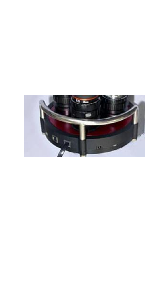
ROTARION CAM 2.5” is a 4 ports remote instrument
selector for mid-to-large size telescopes, patented in
E.U., USA and Australia.
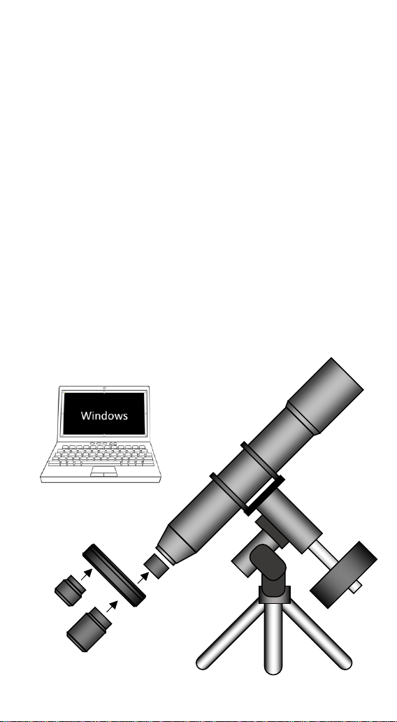
For the first time ever, you can remotely change
cameras and other instruments on your telescope
with just a simple click, connecting your ROTARION
CAM 2.5” remotely to a Windows computer with the
ROTARION REMOTE CONTROL PRO ASCOM
compatible software included in this box.
ROTARION makes your instruments changes easy.
Automatic, quick, and precise without touching the
telescope avoiding disturbances in the positioning or
misalignment of the optical axis between cameras.
Ideal for unmanned remote telescope imaging
operations.
The automatic change allows you to select the
correct instrument on your telescope for the chosen
sky object. All in a single tube telescope.
ROTARION is a device of the highest quality,
designed and manufactured in BARCELONA with
state-of-the-art techniques and the best materials
and components from the US, Japan, and Germany.
Maximum quality, universal, versatile, and easy to
use, ROTARION CAM 2.5” USA Model continues our
corporate mission:
AstronSCIENTIFIC
Astronomy Made Easy

In the box
•ROTARION CAM 2.5” USA Model.
•One USB Stick / Pen-Drive for installing the ROTARION
REMOTE CONTROL software for PC or Windows
computer.
•USB cable for Windows computer control.
•Serial cable for Windows computer control, included
the Serial-to-USB converter.
•AC Power Adapter 110-240 Volt / DC 12 Volt with
international AC adapters.
•User's manual.
•Telescope, telescope adapter rings, eyepieces, optics,
cameras, or other instruments, and other ROTARION
products or accessories are not included.

System Requirements
To operate ROTARION CAM 2.5” and ROTARION REMOTE
CONTROL PRO software you need the following
equipment:
Not included in the box:
•A telescope (A).
•A mount and telescope tripod or column that
supports the weight of the telescope, and the weight
of: your Rotarion CAM 2.5”, the accessories, adapter
parts, and your optics and instruments weight (B).
•Optics, Cameras, Accessories and telescope adapter
rings and barrel (C).
•A Windows PC (D).
Included in the box:
•ROTARION CAM 2.5” (E).
•ROTARION REMOTE CONTROL Software.
(A)
(B)
(C)
(D)
(E)
(C)

Index
A-ROTARION REMOTE CONTROL Software
1. Installing the Software
2. Connecting the ROTARION
3. Status LED
4. Startup of ROTARION
5. ROTARION REMOTE CONTROL screen
6. Setup screen
7. ROTARION REMOTE CONTROL Ports
8. Warning Messages
B-Using the ROTARION and ROTARION
REMOTE CONTROL Software
1. CAUTION! MOVING PARTS!
2. Observing position
3. Observing objects with the ROTARION
4. The "Zoom Effect"
5. The "Finder Effect"
6. The Multi-Camera Telescope
7. Placing Rotarion in your telescope
8. Balancing Rotarion’s carrousel.
C-Additional Product Information
1. Product Compliance Information
2. Service, Maintenance, Cleaning, Disposal, Serial
Number, and Dealer
D-Warranty
1. Warranty Period
2. Warranty Coverage
3. Warranty Nullity

A-ROTARION REMOTE
CONTROL Software
1. Software Installation
To install the ROTARION REMOTE CONTROL software you
need a computer or PC with Windows and a USB
connector.
Load the Pen-Drive / USB-Stick included. On the Pen-Drive
/ USB-Stick you will find the installation file of the
ROTARION CAM 2.5” program called "Setup". Run that file
and follow the instructions to install the program.
The program will be located in the Windows Start menu
under Programs> ROTARION> ROTARION REMOTE
CONTROL.
No need to install drivers for the ROTARION. The USB port
is an HID device that Windows recognizes automatically
and the serial port input does not use a special driver.
Once the installation is completed, the next time you
connect the ROTARION to your computer, it will remember
that this device has already been installed and will
recognize it automatically.

2. Connecting the ROTARION
The ROTARION CAM 2.5” has 3 options for interface
control. Two options are with the ROTARION REMOTE
CONTROL software through a USB port, or via a Serial port
or a third option using the ROTATRION HAND CONTROL
that does not require a Windows PC.
USB connection: If USB port is used to control the
ROTARION wheel, the only required connection is a USB
cable included in the box between the USB port of the
ROTARION CAM 2.5” (3) and a USB port of the computer
or Windows PC.
If the USB port does not have sufficient power, or if you are
using the ROTARION PHOTO accessory, it is necessary to
connect the 12-volt power supply to the power input (1).
(1) Power input
(2) Serial Port
(3) USB Port
(4) Status Led
(5) Focuser Port
ROTARION EyepieceWheel connectors
5
4
3
2
1

Serial Port Connection: If controlled via the serial port,
also be controlled via a serial port, it requires a special RJ12
cable labeled "R-S", included in the box, connected
between the serial port of the ROTARION (2) and a serial
port on the Windows computer or PC.
This interface is mandatory if you are going to use the
ROTARION AUTOFOCUS accessory.
Serial port control does not require any special drivers.
Only determine the correct COM port in the [SETUP] panel
drop-down list (Chapter 4, item 10).
For this interface, it is necessary to connect the 12-volt
power supply to the input (1).
Connection ROTATION HAND CONTROL: It can also be
controlled via a handset via the serial connection (2).
ROTARION HAND CONTROL is available from
AstronSCIENTIFIC distributors. The kit includes a
ROTARION HAND CONTROL with Bluetooth, the
ROTARION AUTOFOCUS software pre-installed (without
the ROTARION AUTOFOCUS hardware) and an RJ12 cable
to connect it to the serial port of the ROTARION CAM 2.5”
(2).
The 12-volt power supply must be connected to the input
(1).
3. Status LED
Normally the LED of the ROTARION (4) is green, changing
to red color when the ROTARION carousel/wheel rotates.
The following table describes all possible cases.

Color
Blink
ROTARION CAM 2.5” STATUS
Green
No
Stopped. Ready to be activated.
Green
Yes
Initial Warning
Red
No
ROTARION Turning
Red
Yes
[ERROR]
4. ROTARION activation
Start the ROTARION REMOTE CONTROL program. This will
initially display the eyepiece wheel control screen.
Press the [SETUP] button (7) to open / close the Setup
panel,
Select the port you are using, USB port or COM port from
the drop-down menu (10).
Press the [QUERY] key (13) to manually connect to the
ROTARION. The next time you start the program, you will
automatically connect to it.
The display shows the initial Warning message, indicating
6 7 8 9 10 11 12 13
1
16
17 18 19
ROTARION REMOTE CONTROL screen. [SETUP] open.

that the ROTARION is ready to start.
REMOVE THE HANDS AND OBJECTS BEFORE PUSHING THE
[RESET] BUTTON.
READ CHAPTER C SECTION 1, CAUTION! MOVING PARTS!
BEFORE PROCEEDING.
Press the [RESET] button (6) and the ROTARION CAM 2.5”
carousel does full rotation movements in one direction and
the opposite direction during which it performs a
calibration and determines the number of available Ports.
When the process is finished, it stops at the [PORT-1]
position. It is ready for use.
5. ROTARION REMOTE
CONTROL screen
The main screen of the ROTARION REMOTE CONTROL
program, with the [SETUP] screen closed, looks like this:
6 7 8
14
16
ROTARION REMOTE CONTROL screen. [SETUP] closed.

[Setup]
Pressing the [SETUP] button (7) opens or closes the set-up
panel, leaving the ROTARION REMOTE CONTROL basic
screen.
[Reset]
For safety reasons, the ROTARION does not start the
turning of the carousel or wheel (A) automatically;
Indicates that it is ready to start the turn and for you to
remove hands, cables, and objects (B) that may interfere
with the turning of the ROTARION carousel before pressing
the [RESET] Button.
By pressing the [RESET] button (6), the ROTARION does full
rotations in one direction and the opposite direction
during which it performs a calibration and determines the
number of available Ports. When the process is finished, it
stops at the [PORT-1] position. It is ready for use.
[Display]
In this display (14) information messages appear during
ROTARION operation. In case of an error or important
MOVING
PARTS!
Wheel
turning (A)
CAUTION!
Remove
hands and
objects! (B)

WARNING, the message with the background illuminated
in Red color appears. For complete information, see the
next point 8, WARNING MESSAGES in this chapter.
[Position Buttons]
Using the [PORT-1] buttons to [PORT-4] (16), you indicate
to the ROTARION REMOTE CONTROL which eyepiece you
will choose. When you press one of them the ROTARION
will rotate to select it. The button lights up when it has
reached the position. The labels of these buttons can be
changed on panel (17) by pressing [SETUP] to access that
screen.
[Panel Orientation]
By pressing the Horizontal / Vertical orientation icon (8),
the ROTARION REMOTE CONTROL screen changes from
portrait to landscape mode and vice versa. You can move
it around the screen by dragging it with the mouse. The
program memorizes the relative Ports of each orientation.
6. Setup screen
Select the [SETUP] button (7) to open the ROTARION
REMOTE CONTROL setup panel.
ROTARION REMOTE CONTROL screen, Horizontal orientation

[Port Selection]
Select the port you are using, USB port or
COM port from the drop-down menu (10).
You can then press the [QUERY] key (13) to manually
connect to the ROTARION; The next time you start the
program ROTARION REMOTE CONTROL will automatically
connect to it.
[Revers]
With box (9) de-activated, the ROTARION CAM 2.5” rotates
in counter clockwise direction only. Activating this box, the
rotation movement is bidirectional, but it limits the
rotating movement to position [PORT-4]; once it reaches
that position the ROTARION can only return to previous
Ports in a revers motion. [Led ON]. Activate this if you
are using heating bands with wires mounted around your
optics or cameras to prevent wires entanglements.
6 7 8 9 10 11 12 13
14
16
17 18 19
ROTARION REMOTE CONTROL Display. Open setup

[LED on]
With the box lit (12), the status LED of the CAM 2.5” (5)
remains lit. Normally the LED is green, changing to red
when the Wheel turns. With the box off (12) you turn off
the LED so that it does not disturb during night
observations or your imaging sessions.
[Close Setup]
Close the ROTARION REMOTE CONTROL configuration
panel (11).
[Query]
When you press [QUERY] (13), the connection to the
ROTARION is started manually. Normally it is not necessary
to press it since when the program is started it is
connected automatically. But if you change the
communication port, the connection is stopped, and it will
necessary to start the connection manually, or to exit and
restart the program.
[Eyepiece Name Panel]
In this panel (17) you can give the name of the eyepiece
that you place in each position. These names will appear
on the home screen. Example: [PORT-1] = 1-TeleVue 40;
[PORT-2] = 2-Meade 28; etc. By means of the boxes (18) it
is possible to cancel a position by unchecking the box.
Useful if you do not mount an eyepiece.
[Focuser Panel]
In this panel (19) you can adjust everything related to the
ROTARION AUTOFOCUS accessory, which is explained in
detail in its own User Manual.

If you have the ROTARION AUTOFOCUS accessory, in the
[FOCUSER CONFIG] Panel you can activate the checkbox
indicated on the previous page [MINI CONTROL], so that
the AUTOFOCUS Control appears at the bottom of the
main screen of the ROTARION REMOTE CONTROL
program.
Please refer to the ROTARION AUTOFOCUS Instruction
Manual.

7. ROTARION REMOTE
CONTROL Ports
GOTO n
When you press the [PORT-1]
button to [PORT-4] the
ROTARION CAM 2.5” begins to
turn until it locates that
position.
During the time its turning,
the display shows WAITING ...
and the keys are locked. Once
the position is reached, the
keys are unlocked and the
selected position lights up.
[PORT-1]
It is the initial position of the
ROTARION once the [RESET]
has been made. In it you must
have installed the eyepiece
with least power or
magnification and largest field of view. This will make it
easier to find the celestial object for observation.
[PORT-2]
In this position, you normally have an eyepiece with a
higher power than the previous [PORT-1]. The visual field
is smaller, but if you have focused the object in [PORT-1],
it is easy to re-focus because the object isin the visual field
of view.
[PORT-3]
In this position, you normally have an eyepiece with a
higher power than the previous [PORT-2]. The visual field
is even smaller, but you have the object in the visual field
of view. You can focus on it again.
GOTO in progress

[PORT-4]
In this position, you normally have an eyepiece with a
higher power than the previous [PORT-2]. The objects
appear larger, and the visual field is smaller, but you have
the object in the field of view. You can focus on it again.
[PORT-5]
This position is not available in this version of the
ROTARION CAM 2.5”.
8. Warning Messages
The display (14) shows warning messages during
ROTARION operation. In case of an error or important
WARNING, the message with the background illuminated
in Red appears.
Initial Warning
Each time you connect the ROTARION REMOTE CONTROL
it is necessary to make a [RESET] (6) to find the position
[PORT-1]. For safety reasons, the ROTARION does not start
[POS-2]
[POS-1]
[POS-3]
[POS-4]

the rotation of the carousel (A) automatically; Indicates
that it is ready to start the turn and that you remove hands,
cables, and objects (B) that may interfere with the rotation
of the ROTARION carousel before pressing the [Reset]
button. The LED (4) flashes green.
Position Error
For safety reasons, when the ROTARION does not find the
next selected position, it interrupts the rotation
movement, it partially inverts the rotation movement to
release any entrapment of objects and indicates ERROR.
Check that there is no wire or object interfering with the
turning of the ROTARION carousel/wheel. The LED (4)
flashes red.
After verifying that no object is interfering with the turning
of the ROTARION, you can press the [RESET] button (6) on
the ROTARION REMOTE CONTROL to restart the device.
Device Not Found
It cannot find ROTARION through the USB connection.
Verify that you are properly connected and powered.
MOVING
PARTS!
Wheel
turning (A)
CAUTION!
Remove
hands and
objects! (B)

Port COM Error
It cannot find ROTARION through the serial connection.
Verify that you are properly connected and powered.
Verify that you have selected a correct [COM] port.
Starting Rotarion
The ROTARION is turning for a [RESET]. The LED (4) lights
red.
Waiting...
The ROTARION is turning during the selection of an
eyepiece. The LED (4) lights red.

B-Using the ROTARION
and ROTARION REMOTE
CONTROL Software.
1. CAUTION! MOVING PARTS!
ROTARION CAM 2.5”, ROTARION REMOTE CONTROL
software and its accessories are not toys, they are optical
instruments with mechanisms only to be used by adults.
The carousel (A) of the ROTARION CAM 2.5” performs
revolving-type turning movements until reaching the
position requested in the ROTARION REMOTE CONTROL
software.
Remove hands, cables, and other nearby objects (B) that
may interfere with the movement of the ROTARION CAM
2.5” carousel, before you order a turn or PORT change in
the ROTARION REMOTE CONTROL software.
If any object interferes with the rotating movement of the
ROTARION CAM 2.5” carousel by generating an
entrapment and preventing reaching the position indicated
in the ROTARION REMOTE CONTROL, the safety system
automatically activates after 0.3 seconds, interrupting the
requested turning movement and performing a partial
reverse rotation to release the trap, indicating an [ERROR]
message on the ROTARION REMOTE CONTROL software
screen.
Table of contents
Other AstronSCIENTIFIC Accessories manuals