manuals.online logo
Brands
  1. Home
  2. •
  3. Brands
  4. •
  5. AstroStart
  6. •
  7. Remote Starter
  8. •
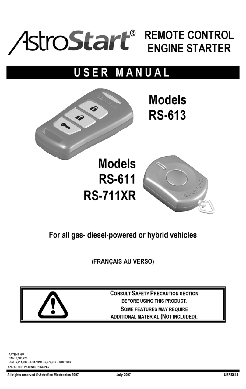
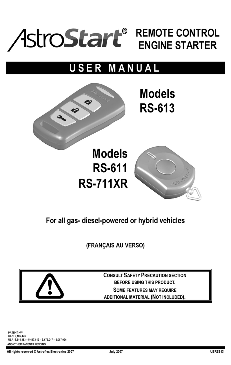
  9. AstroStart RS-611 User manual

AstroStart RS-611 User manual

REMOTE
ENGINE
STARTER
INSTALLATION MANUAL
MODELS RS-611
RS-613
DESIGNED
FOR ALL HYBRID,
GAS-,AND DIESEL-POWERED
AUTOMOBILES
THIS PRODUCT MUST BE INSTALLED BY
QUALIFIED PERSONNEL.
WHEN THIS PRODUCT IS INSTALLED ON A VEHICLE WITH
MANUAL TRANSMISSION, THE INSTALLATION MUST
INCLUDE A MANUAL INTERFACE
(SOLD SEPARATELY - No. RS-MI).
188 ST-FRANÇOIS XAVIER
DELSON, QUEBEC J5B 1X9
MORE DETAILED INFORMATION CAN BE FOUND
IN THE “DEALER” SECTION OF OUR WEBSITE:
WWW.ASTROFLEX.COM/DEALER
AND IN THE ASTROCHART PROGRAM
ISBRS613 07 07
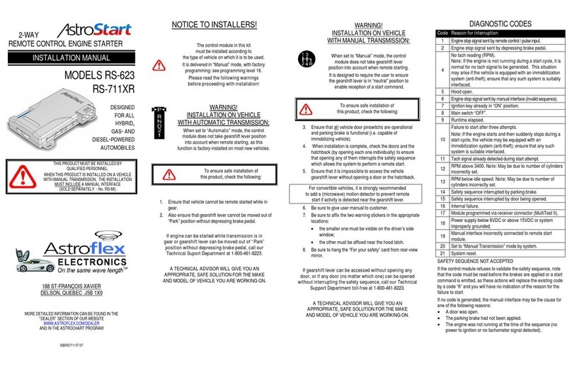
NOTICE TO INSTALLERS!
The control module in this kit must
be installed according tothe type of
vehicle on which it is to be used.
It is delivered in “Manual” mode, with factory
programming: see programming level 1.
Please read the following warnings before
proceeding with installation!
WARNING!
INSTALLATION ON VEHICLE
WITH AUTOMATIC TRANSMISSION:
When set to “Automatic” mode, the control
module does not take gearshift lever position into
account when remote starting, as this function
is factory-installed on most new vehicles.
To ensure safe installation of this,
product check the following:
1. Ensure that vehicle cannot be remote started while in
gear.
2. Also ensure that gearshift lever cannot be moved out
of “Park” position without depressing brake pedal.
If engine can be started while transmission is in gear
or gearshift lever can be moved out of “Park” position
without depressing brake pedal, call our Technical
Support Department toll-free at 1-800-461-8223.
A TECHNICAL ADVISOR WILL GIVE YOU AN
APPROPRIATE, SAFE SOLUTION FOR THE MAKE
AND MODEL OF VEHICLE YOU ARE WORKING ON.
WARNING!
INSTALLATION ON VEHICLE WITH
MANUAL TRANSMISSION:
When set to “Manual” mode, the
control module does not take gearshift lever
position into account when remote starting.
It is designed to require the user to ensure
the gearshift lever is in “neutral” position to
enable reception of a start command.
To ensure safe installation of this
product, check the following:
3. Ensure that all vehicle door pinswitches are
operational and parking brake is functional (i.e.
capable of immobilizing vehicle).
4. When installation is complete, check the doors and the
hatchback (by opening each one individually) to
ensure that opening any of them interrupts the safety
sequence which allows the system to perform a
remote start.
5. Ensure that it is impossible to access the vehicle
gearshift lever without opening a door or the
hatchback.
For convertible vehicles, it is strongly recommended
to add a (microwave) motion detector to prevent remote
start if activity is detected near the gearshift lever.
6. Be sure to give user manual to customer.
7. Be sure to affix the two warning stickers in the
appropriate locations:
•the smaller one must be visible on the driver’s
side window;
•the other must be affixed near the hood latch.
8. Be sure to hang the “For your safety” card from rear-
view mirror.
If gearshift lever can be accessed without opening
any door, or if any door (no matter which one) can be
opened without interrupting the safety sequence, call our
Technical Support Department toll-free at 1-800-461-8223.
A TECHNICAL ADVISOR WILL GIVE YOU AN
APPROPRIATE, SAFE SOLUTION FOR THE MAKE
AND MODEL OF VEHICLE YOU ARE WORKING ON.
DIAGNOSTIC CODES
Code
Reason for interruption
1 Engine stop signal sent by remote control / pulse input -
H10.
2 Engine stop signal sent by depressing brake pedal.
4
No tach reading (RPM).
Note: If the engine is not running during a start cycle, it
is normal for no tach signal to be generated. This
situation may arise if the vehicle is equipped with an
immoblilization system (anti-theft); ensure that any such
system is suitably interfaced.
5 Hood open.
6 Engine stop signal sent by manual interface
(invalid sequence).
7 Ignitiion key already in “ON” position.
8 Main switch “OFF”.
9 Runtime elapsed.
10
Failure to start after three attempts.
Note: If the engine starts and then suddenly stops
during a start cycle, the vehicle may be equipped
with an immobilization system (anti-theft); ensure
that any such system is suitable interfaced.
11 Tach signal already detected during start attempt.
13 RPM below idle speed. Note: May be due to number of
cylinders incorrectly set.
14 Safety sequence interrupted by parking brake.
15 Safety sequence interrupted by door being opened.
16 Internal failure.
17 Module programmed via receiver connector (Multi Test II).
18 Power supply below 8VDC or above 15 VDC or system
improperly grounded.
19 Manual interface incorrectly connected to remote start
module.
20 Set to “Manual Transmission” mode by system.
21 System reset.
SAFETY SEQUENCE NOT ACCEPTED
If the control module refuses to validate the safety sequence, note
that the code must be read before the brakes are applied or a
start command is emitted, as these actions will replace the
existing code by a code “6” and you will have no indication of the
reason for failure to start.
If no code is generated, the manual interface may be the cause
for one of the following reasons:
•A door was open.
•The parking brake had not been applied.
•The engine was not running at the time of the sequence (no
power to ignition or no tachometer signal detected).

LEGEND / COMMENTS
IGNITION
SWITCH
“OFF”/“ON”
SELECT
NEXT
OPTION SELECT
PREVIOUS
OPTION
OFF ON MAIN SWITCH
“OFF”/“ON” DEPRESS
BRAKE PEDAL OR
LED THE LED FLASHES THE NUMBER OF TIMES INDICATED IN THE
TABLE TO CONFIRM THE SELECTION OF A LEVEL,PARAMETER
OR OPTION.
•THE FIRST TIME AN OPTION IS SELECTED,THE LED DISPLAYS THE CURRENT
SETTING;CHANGES ARE MADE ONLY THE SECOND TIME IT IS SELECTED AND
SUBSEQUENTLY.
•A SELECTED OPTION IS ONLY MEMORIZED WHEN THE BRAKE PEDAL IS
DEPRESSED.
•TURNING THE IGNITION SWITCH TO “OFF”AT ANY TIME TERMINATES
PROGRAMMING.
•ONLY ONE LEVEL MAY BE SET AT A TIME.FINISH THE CURRENT LEVEL AND
START THE PROCESS OVER FOR THE NEXT LEVEL.
PROGRAMMING / CONNEC
TION DIAGRAM
1 LEVEL1
BASICCONFIGURATION
1 TRANSMISSION -SAFETY SEQUENCE
1 AUTOMATIC TRANSMISSION
2 MANUAL –2PARKING BREAK ACTIVATION
3 MANUAL –1PARKING BREAK ACTIVATION
4 MANUAL -INITIALIZED BY TX -END BY TX
5 MANUAL -INITIALIZED BY TX -
END BY CLOSING DOOR
2 NUMBER OF CYLINDERS PER TACHOMETER CIRCUIT
1 1CYLINDER
2 2CYLINDERS
3 3-4CYLINDERS
4 5-6CYLINDERS
5 8CYLINDERS
6 10CYLINDERS
7 12CYLINDERS
3 STARTER DISENGAGE (TACH MODE)
1 800RPM
2 500RPM
4 TACHOMETER SIGNAL READING MODE
1 SIGNAL MONITORING MODE
2 “TACHLESS”MODE TYPE 1
3 “TACHLESS”MODE TYPE 2
4 “TACHLESS”MODE TYPE 3
5 HYBRID MODE
5 RUNTIME
1 2MIN./4MIN.
2 4MIN./8MIN.
3 8MIN./16MIN.
4 18MIN./36MIN.
6 ENGINE TYPE
1 GASOLINE
2 DIESEL 15SEC.
3 DIESEL 30SEC.
7 HOOD SWITCH TYPE
1 NORMALLY CLOSED
2 NORMALLY OPEN
2 LEVEL2
ADVANCED CONFIGURATION
1 UN/LOCK PULSE TYPE
1 SINGLE
2 DOUBLE
2 UN/LOCK PULSE DURATION
1 0.7SECOND
2 2.8SECONDS
3 TRUNK RELEASE PULSE DURATION
1 0.7SECOND
2 15SECONDS
3 1MINUTE
4 8MINUTES
4 AUTOMATIC UN/LOCK
1 ENABLED
2 DISABLED
5 OEM ALARM SYSTEM REARMING
1 DISABLED
2 TYPE 1
3 TYPE 2
6 HORN CONFIRMATION
1 DISABLED
2 2ND START
3 2ND UNLOCK
4 2ND UNLOCK AND 2ND START
7 PULSE ON UN/LOCK OUTPUT
1 DISABLED
2 PULSE BEFORE START ON UNLOCK OUTPUT
3 PULSE AFTER START ON LOCK OUTPUT
4 BOTH (OPTIONS 2AND 3ENABLED)
8 COMMUNICATION PROTOCOL –ASTROLINK PORT
1 DISABLED
2 DATA TO DATA
9 PROGRAMMABLEOUTPUT#1-H3-4 -BROWN 
10 PROGRAMMABLEOUTPUT #2-H3-3-WHITE/BLUE 
11 PROGRAMMABLEOUTPUT#3-H3-2 -WHITE 
12 PROGRAMMABLEOUTPUT#4-H3-1 -VIOLET 
13 PROGRAMMABLEFUNCTIONRELAY-H11 
PARAMETER CORRESPONDING TO DEFAULT OPTION
9 1 PULSE BEFORE START ON UNLOCK OUTPUT
10
2 PULSE AFTER START ON LOCK OUTPUT
13
3 ACTIVATED WHILE RUNNING
4 ACTIVATED 5SEC.WHILE RUNNING
5 PARKING LIGHTS
6 2ND UNLOCK
7 IGNITION
8 ACCESSORIES
11
9 START
12
10
TRUNK RELEASE
11
DOME LIGHT
12
HORN
3 LEVEL3
INITIAL PROGRAMMING (RESET)
When this level is selected, programming is reset
to original factory settings.
Default parameters are indicated by boxes highlighted in yellow
(different colours for parameters 9 to 13).
NIVEAU DEL
PREMIER PARAMÈTRE 1
PREMIÈRE OPTION 1
OPTION COURANTE 2
OU
DERNIÈRE OPTION 3
PARAMÈTRE SUIVANT 2
PREMIÈRE OPTION 1
OPTION COURANTE 2
OU
DERNIÈRE OPTION 3
DERNIER PARAMÈTRE 3
PREMIÈRE OPTION 1
OPTION COURANTE 2
OU
DERNIÈRE OPTION 3
6 SEC.
FIN
OFF ON NIVEAU 2

OFF ON NIVEAU 3
OFF ON

OFF ON 
OFF ON NIVEAU 1 OFF ON

ON
DÉBUT
FIN

FIN


OFF ON
OFF ON
OFF ON
FIN
OPTIONS
PAR
DÉFAUT
OFF
START
END
6 sec.
LEVEL 1
LEVEL 2
LEVEL 3
DEFAULT
OPTION
LEVEL
FIRSTOPTION
CURRENTOPTION
LASTOPTION
OR
FIRSTOPTION
CURRENTOPTION
LASTOPTION
OR
FIRSTOPTION
CURRENT OPTION
LASTOPTION
OR
LED
FIRST PARAMETER
FOLLOWING PARAMETER
LAST PARAMETER
END
END
END
DIAGNOSTIC
LED
+
F2 - 10A
H11 PROGRAMMABLE RELAY
J1
PARKING LIGHT POLARITY
PROGRAMMING JUMPER
(H1-GREEN)
F1 - 25A
F3 - 25A
COMMON (30)
N.C. (87A)
N.O. (87)
H10 ACCESSORY INTERFACES
-
H1 POWER SUPPLY / POWER OUTPUTS
RED: 12VDC INPUT (+)
ORANGE:
IGNITION OUTPUT (+) – PROTECTED BY F1 (25A)
YELLOW: ACCESSORY OUTPUT (+) - PROTECTED BY F3 (25A)
GREEN: PARKING LIGHTS OUTPUT (±) – POWERED BY F1 (25A)
RED/BLACK: 12VDC INPUT (+)
BLUE: STARTING OUTPUT (+) - PROTECTED BY F1 (25A)
H2 UN/LOCK OUTPUT
BROWN: LOCK OUTPUT (-) 500mA
RED: 12VDC OUTPUT (+) 500mA
BLUE: UNLOCK OUTPUT (-) 500mA
H3 PROGRAMMABLE OUTPUTS
VIOLET: PROGRAMMABLE OUTPUT #4 (-) 200mA - SEE LEVEL 2-12
WHITE: PROGRAMMABLE OUTPUT #3 (-) 200mA - SEE LEVEL 2-11
WHITE/BLUE: PROGRAMMABLE OUTPUT #2 (-) 200mA - SEE LEVEL 2-10
BROWN: PROGRAMMABLE OUTPUT #1 (-) 200mA - SEE LEVEL 2-9
YELLOW: PULSE START INPUT (-)
H4 ON/OFF SWITCH
H5 ANTENNA / RECEIVER
H6 CONTROL SIGNALS
GREEN: OUTPUT WHEN RUNNING (-) 200mA
BLACK/RED: INTERRUPT INPUT (-) - HOOD SWITCH
WHITE/GREEN: INTERRUPT INPUT (+) - BRAKE
BLACK: GROUND (-)
NO CONNECTION
BLACK/GREEN: TACHOMETER SIGNAL INPUT
H7 ASTROLINK
H8 MANUAL INTERFACE

Other manuals for RS-611

1

This manual suits for next models

1

Other AstroStart Remote Starter manuals

AstroStart 1105U User manual

AstroStart

AstroStart 1105U User manual

AstroStart 2305A User manual

AstroStart

AstroStart 2305A User manual

AstroStart 4204 User manual

AstroStart

AstroStart 4204 User manual

AstroStart 2205U User manual

AstroStart

AstroStart 2205U User manual

AstroStart 4104 User manual

AstroStart

AstroStart 4104 User manual

AstroStart DSP611 User manual

AstroStart

AstroStart DSP611 User manual

AstroStart series 1100 User manual

AstroStart

AstroStart series 1100 User manual

AstroStart 2006 User manual

AstroStart

AstroStart 2006 User manual

AstroStart 502 User manual

AstroStart

AstroStart 502 User manual

AstroStart 803U User manual

AstroStart

AstroStart 803U User manual

AstroStart RS-623 User manual

AstroStart

AstroStart RS-623 User manual

AstroStart RS-213 User manual

AstroStart

AstroStart RS-213 User manual

AstroStart RS-655 User manual

AstroStart

AstroStart RS-655 User manual

AstroStart RS-623 User manual

AstroStart

AstroStart RS-623 User manual

AstroStart 2101 User manual

AstroStart

AstroStart 2101 User manual

AstroStart 2205A User manual

AstroStart

AstroStart 2205A User manual

AstroStart AF-RFS2625 User manual

AstroStart

AstroStart AF-RFS2625 User manual

AstroStart RSS-5224 User manual

AstroStart

AstroStart RSS-5224 User manual

AstroStart QS-5 User manual

AstroStart

AstroStart QS-5 User manual

AstroStart RS-611 User manual

AstroStart

AstroStart RS-611 User manual

AstroStart 803 User manual

AstroStart

AstroStart 803 User manual

AstroStart RSS-2514XR User manual

AstroStart

AstroStart RSS-2514XR User manual

AstroStart TS-100 User manual

AstroStart

AstroStart TS-100 User manual

AstroStart RSi1 1D User manual

AstroStart

AstroStart RSi1 1D User manual

Popular Remote Starter manuals by other brands

Intec i-starter 6.0 user manual

Intec

Intec i-starter 6.0 user manual

ProStart ProStart CT-5460TW user guide

ProStart

ProStart ProStart CT-5460TW user guide

Battery Tender 392 0424 RB instruction manual

Battery Tender

Battery Tender 392 0424 RB instruction manual

FLYLINKTECH CF200 user manual

FLYLINKTECH

FLYLINKTECH CF200 user manual

Firstech FT-EZGO Quick setup

Firstech

Firstech FT-EZGO Quick setup

iMars J03 user manual

iMars

iMars J03 user manual

CompuSTAR FT-MBKG20-HRN installation guide

CompuSTAR

CompuSTAR FT-MBKG20-HRN installation guide

Voxx Electronics CA-510 installation instructions

Voxx Electronics

Voxx Electronics CA-510 installation instructions

NOCO Genius BOOST MAX GB251+ user manual

NOCO Genius

NOCO Genius BOOST MAX GB251+ user manual

Linear AE2000PLUS installation instructions

Linear

Linear AE2000PLUS installation instructions

HI-Q TOOLS PM400 user guide

HI-Q TOOLS

HI-Q TOOLS PM400 user guide

Westfalia Jumper instruction manual

Westfalia

Westfalia Jumper instruction manual

Smartech JS-8000N user guide

Smartech

Smartech JS-8000N user guide

Fortin EVO-START install guide

Fortin

Fortin EVO-START install guide

Sealey POWERSTART200 instructions

Sealey

Sealey POWERSTART200 instructions

Audiovox Prestige APS-905 installation manual

Audiovox

Audiovox Prestige APS-905 installation manual

Firstech 1BAMR-Chrome user manual

Firstech

Firstech 1BAMR-Chrome user manual

Prestige APS901Z owner's guide

Prestige

Prestige APS901Z owner's guide

manuals.online logo
manuals.online logoBrands
  • About & Mission
  • Contact us
  • Privacy Policy
  • Terms and Conditions

Copyright 2025 Manuals.Online. All Rights Reserved.