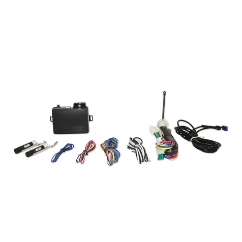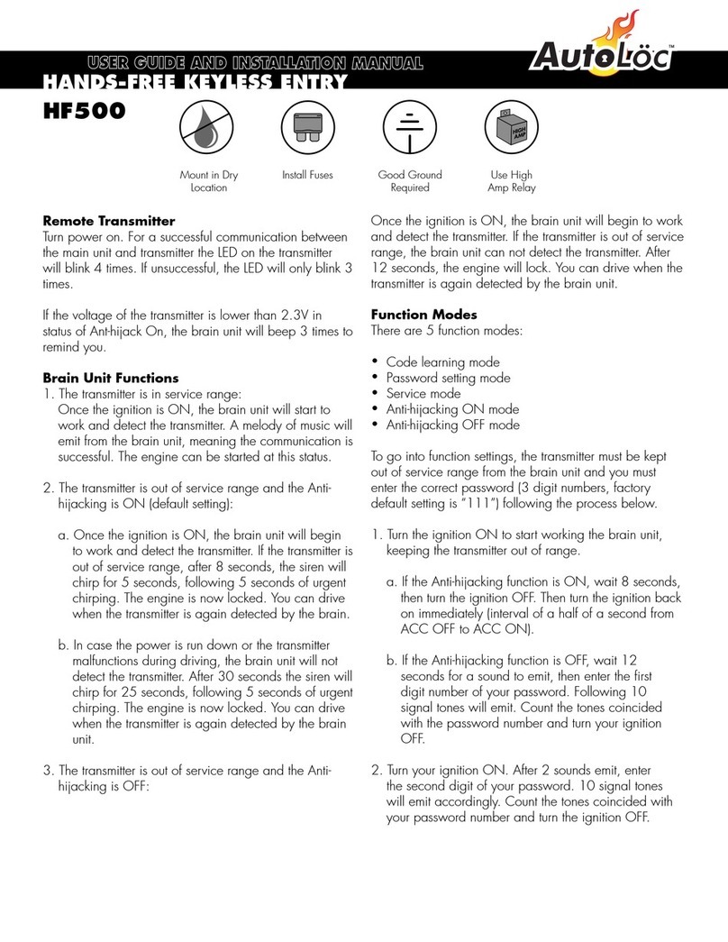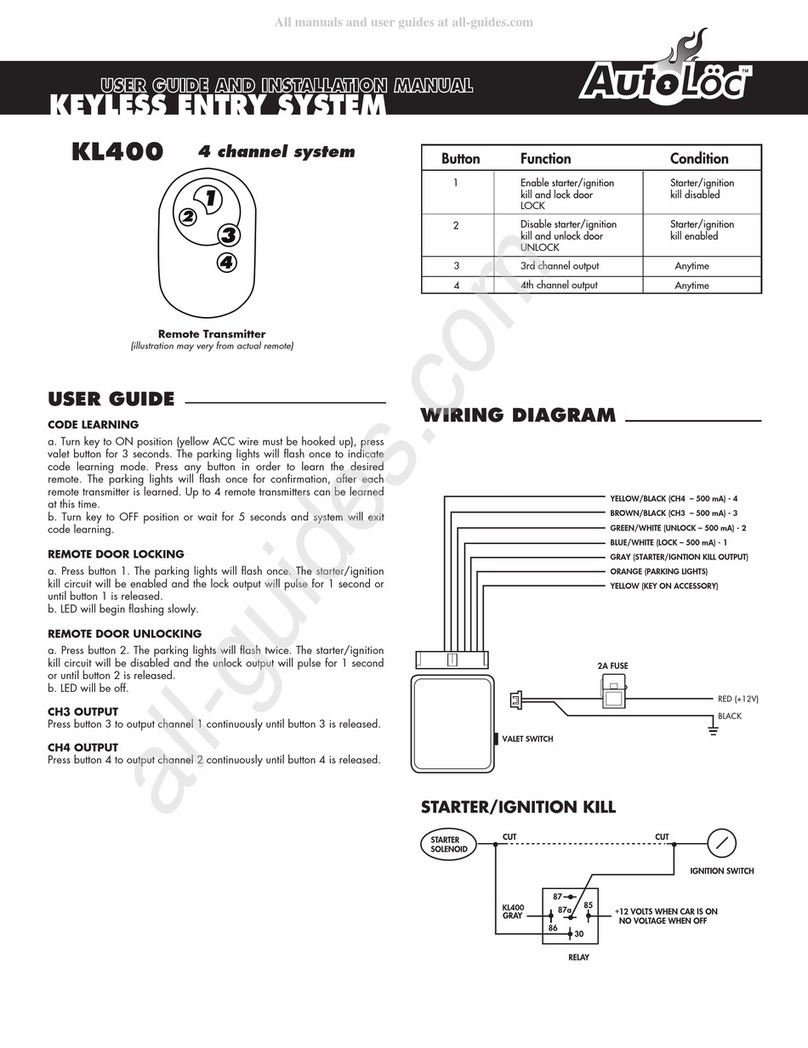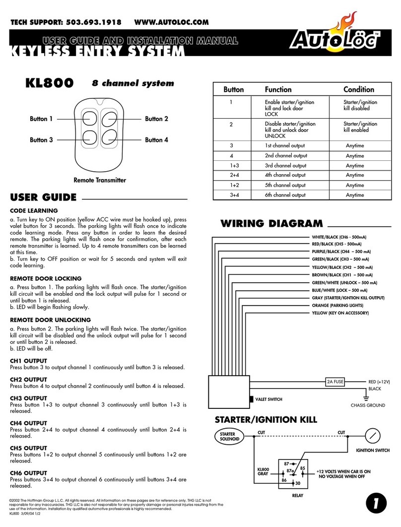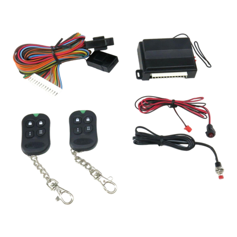
REMOTE/PUSH BUTTON START
Programmable Control Module
AUTEC0 #54309
IMPORTANT INFORMATION!
You must use relays on ALL outputs
except for Status LED output.
All outputs are negative trigger.
1
2
The AUTEC0 is indeed a fantastic device-
with one single button (or other input) you
can turn on your accessory circuit AND your
ignition, together or separate. The following
instructions will serve as a valuable guide
to the correct wiring of this amazing unit.
Unit Operation
Accessory Operation Device Diagram
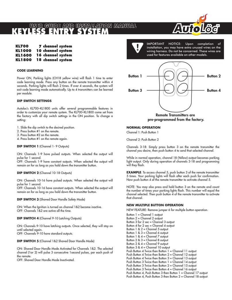
1. Press button (blue input 1) for 1 second
to turn on accessory mode (radio, etc.).
2. Press button again (blue input 1) for 1
second to turn accessory mode off.
*Trigger polarity (+/-) is selectable on
option 8 of the programming menu.
0 = negative
1 = positive
Setting Crank Duration
1. Press button 1 for 5 seconds. Display
will light.
2. Use buttons 2 and 3 to get display to
indicate the number 2.
3. Press button 1 once to confirm selected
time mode (3), then press button 2 or 3 to
select the desired output time in half-sec-
ond intervals. (cranking time)
4. Press button 1 once to confirm selected
output time.
5. Press button 1 once or wait ten
seconds and the device will exit time
setting mode.
Starter/Ignition Operation
1. Press button (blue input 1) for more than 3
seconds. Ignition and accessory will activate
after 2 seconds, and starter will crank for a
programmed length of time.
2. To turn vehicle off, press and hold button
(blue input 1) for more than three seconds.
Numeric Display
Starter
+12v
+12v
Ignition1Ignition2 Accessory
Button1
Red +12v
Black Ground
Blue Input 1 (Button)
Purple
(NOT USED)
Yellow (NOT USED)
Green STARTER
GREY IGNITION2
Brown IGNITION1
White ACCESSORY
Not Used
Button2
Button3
+12v
+12v
+12v
+12v
+12v
+12v
LED +
LED –
Orange
