ASUNA 9700 User manual

ASUNA 9700 Elevated
Performance Treadmill
Workstation

INDEX
We reserve the right to make change at any time without notice,
in colors, parts and materials.
ASSEMBLY PARTS LIST......................................................................................
ASSEMBLY INSTRUCTIONS..............................................................................
MOVING & LEVELING..........................................................................................
HOW TO OPERATE..............................................................................................
ADJUSTING THE RUNNING BELT TENSION...........................................
CLEANING AND INSPECTING THE RUNNING BELT..............................
CLEANING.........................................................................................................
INSPECTING FASTENERS AND WIRING...................................................
STORAGE...........................................................................................................
ERROR CODE & TROUBLESHOOTING.............................................................
PROFILE FOR PROGRAMS................................................................................
TREADMILL OPERATION...............................................................................
MAINTENANCE.................................................................................................
IMPORTANT SAFETY INSTRUCTIONS.............................................................
ELECTRICAL GROUNDING INSRUCTIONS.....................................................
13 - 14
19 - 26
30
CAUTION: BEFORE AND AFTER RUNNING ON THE TREADMILL...............
RUNNING DECK LUBRICATION........................................................................
27
28
28
28
29
8
9 - 12
12
14 - 18
29
29
EXPLODED DIAGRAM............................................................................................
PARTS LIST.......................................................................................................
ALIGNING THE RUNNING BELT...................................................................
6 - 7
1 - 2
2
3
3 - 4
5

1
IMPORTANT SAFETY INSTRUCTIONS
1. This treadmill requires a dedicated circuit as 110 V / 220 V, 15 / 10 AMP separately that is not
shared by any other electrical appliances. Failure to do so can damage the electronics and the
motor and will void the warranty.
2. To reduce the risk of electric shock, always unplug the power cord from electrical outlet
immediately after use and before cleaning, assembling, or servicing.
3. Never leave the treadmill unattended when plugged in. Disconnect by turning off the master power
switch and unplugging the unit from the outlet.
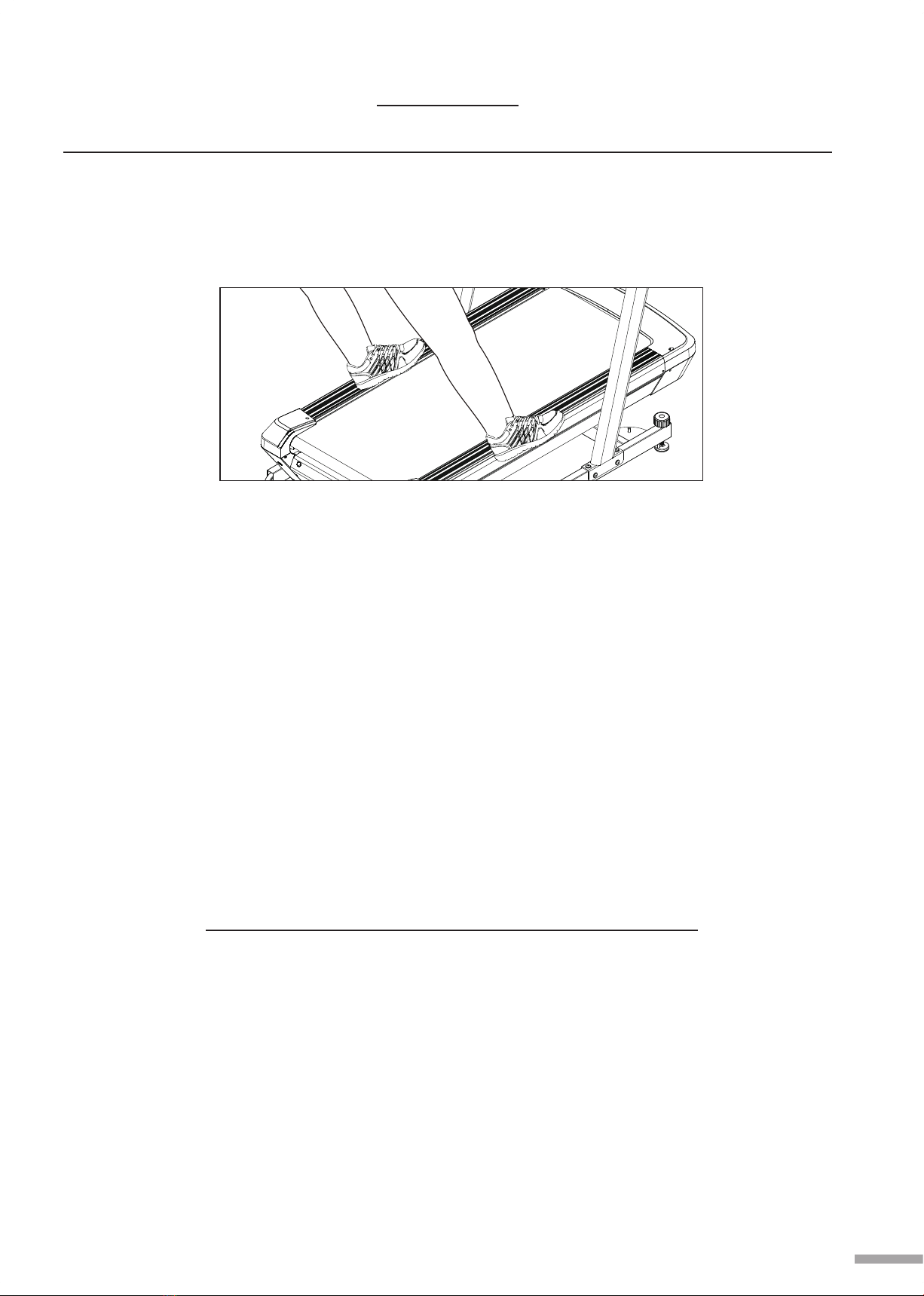
4. Always keep hands and feet off the treadmill while others are using it.
5. Never place hands or feet under the treadmill.
6. Do not allow children on or around the treadmill.
Please read the following basic precautions prior to use of the treadmill:
* Never operate the treadmill with the air openings blocked.
* Keep air openings free of lint, hair and alike items.
* Please retain this manual for future reference.
WARNING
CAUTION
1. The built-in pulse sensing feature of this treadmill was designed for exercise use only and should
not be used for medical purpose.
2. Never operate the treadmill if it has been dropped, damaged, or exposed with to water. Contact
your distributor for service recommendations.
3. Before starting any exercise program, it is recommended that you consult with your physician.
4. Stop using treadmill if you feel dizziness or discomfort.
5. Medical approval and close supervision are necessary when the treadmill is used by or near
individuals with medical conditions.
6. Use the treadmill only for its intended use as described in this manual.
7. Do not pull or grip the treadmill by the power cable during storage or use of this treadmill.
8. Keep power cable away from heated surfaces and open flame.
9. Do not use or store treadmill outdoors.
10. Do not operate this treadmill where aerosol products are being used or where oxygen is being
administered.
11. While turning on the power, please stand beside the treadmill, not on the treadmill.
12. Maximum Weight Capacity is 300 LBS (136 KGS).
13. Do not operate this treadmill in wet or moist environment.
14. Do not use the treadmill on carpet that is more than 1/2 inch thick.
15. Do not operate under a blanket. Excessive heating can occur and cause fire, electrical shock, or
injury to persons.
16. Never insert any objects into any opening on the treadmill.
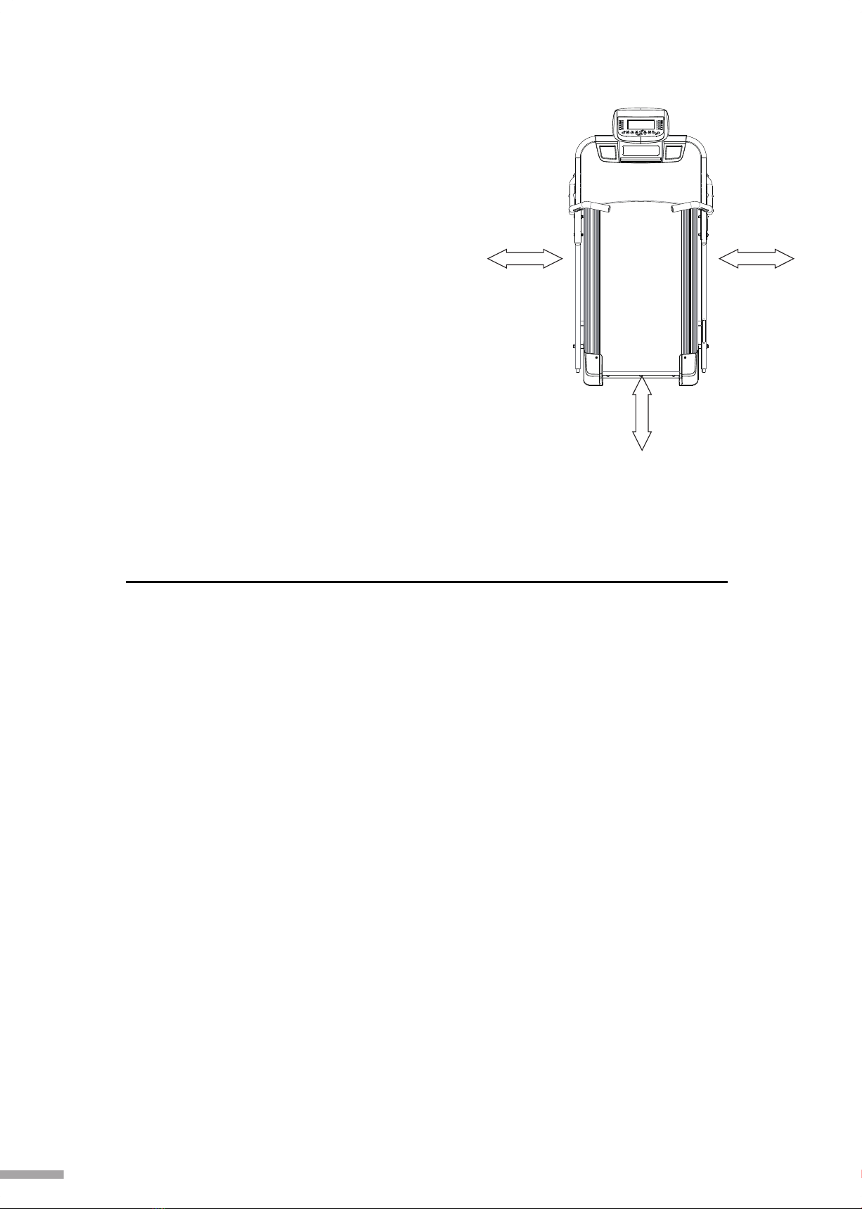
17. Keep this treadmill on a solid, level surface with sides at least two feet from any walls. Be sure
the area around the treadmill remains clear during use and has adequate clearance. See
illustration below.

2
The difference in the RPM of motor is +/- 10%
ELECTRICAL GROUNDING INSTRUCTIONS
2 FEET MIN.
2 FEET MIN.
LEFT
SIDE
REAR
TO P
VIEW
FRON T
2 FEET MIN.
RIGH T
SIDE
18. Do not walk or jog barefoot or without shoes.
19. Do not walk or jog in loose shoes or slippers.
Athletic shoes are always recommended
while using this treadmill.
20. Never walk or jog while wearing loose fitting
clothing.
21. When walking or jogging always stay on the
forward part of the treadmill.
22. Never jog or walk faster than it is comfortable
for you.
23. Do not jump on the treadmill or from side to
side.
24. Do not place any liquid on any parts of the
treadmill.
25. Do not plug anything into the same outlet with
any other electrical appliance while using this
treadmill.
This product must be grounded. When there is
malfunction or break down, grounding provides
a path of least resistance for the electric
current, reducing the risk of electric shock. This
treadmill is equipped with a cord that has an
equipment grounding connector and a
grounding plug. The power cord must be
plugged into an appropriate outlet that is
properly installed and grounded in accordance
with all local codes and ordinances.
DANGER
Improper connection of the treadmill grounding
can result in the risk of electric shock. Check
with a qualified electrician if you are in doubt as
to whether the product is properly grounded.
Do not modify the plug provided with the
treadmill.
If it does not fit your outlet, have a properly
grounded outlet installed by a qualified
electrician.
This unit must be plugged into a nominal 110
volt,15 AMP or 220 volt, 10 AMP circuit, which
has a grounding plug. Outlets that service
multiple appliances, or have fluctuating voltage
of more than 5%, may result in erratic
performance or cause damage to the treadmill
electronics. Using electrical power other than
that which has been specified will ultimately
void any warranty.
Never remove or bypass the electrical ground
contained in the treadmill's three-lug with an
adapter.

CAUTION
BEFORE AND AFTER RUNNING ON THE TREADMILL
Before Running:
1. Read the manual first to be familiar with the digital display and other important features.
2. Before starting the treadmill, always stand on the two side rails on both sides (not on the
running belt) as shown in the drawing.
3. Press in Safety Key underneath the display and have the safety clip securely attached
to an article of clothing.
4. Start the treadmill and allow it to reach a speed of at least 0.6 mph, grip handlebars before
beginning, then walk on the running belt to start your exercise program.
After Running:
1. If you hear any abnormal noises from the motor, please stop usingthistreadmill immediately
and contact your distributor for necessary maintenance.
2. Please refer to page 3-4 RUNNING DECK LUBRICATION to do necessary periodical
maintenance for long-term and functional operation.
3
FAIL TO PERFORM PERIODICAL MAINTENANCE MIGHT VOID THE WARRANTY.
RUNNING DECK LUBRICATION
Why lubricate?
If the lubricant dries out, the friction between the belt and the deck will rise and place undue
stress on the drive motor, drive belt and electronic motor control board. This could result in
catastrophic failure of these expensive components.
When to lubricate?
A high-efficient and low-friction running deck is used on this treadmill. The deck comes pre-
lubricated and subsequent lubrication should be done every 112 miles, or every 3 months of
operation, whichever comes first. Keeping the running deck lubricated at the recommended
period ensures the longest life possible for your treadmill.

4
123
How to lubricate?
Follow above diagram, lift running belt as high as possible, and wipe the deck and the edge of
the belt with a clean lint free cloth to remove any dirt on both sides. Then, insert the straw from
the silicone bottle from either side of the running belt to reach to the running deck surface
about 18 inches from motor cover. Pump out the silicone of the tube across the running deck
parallel to the motor cover for about one foot long. This one foot line should be in the middle of
the deck at approximately equal distance from both side edges of the running belt. Repeat
above procedures to distribute onto 3 spots on the running deck as shown on drawing. Once
the silicone is applied, you should walk, not run, at a low speed on the treadmill for at least 5
minutes to ensure it is evenly distributed.
You want the lubricant to be applied about the spot that your feet would hit the belt as you are
walking. This should be about 18 inches from the motor front cover. You may walk on the
treadmill to see where your feet land on the belt. Please note if you mostly run on the treadmill,
the spot where your feet land may be different from the spot when walking.
Note:
1.
2.
3.
If the belt is stuck under the side rail cover, use a screwdriver to lift the running
belt (be careful to not scratch the running deck) to allow lubrication.
If the belt is not centered, please refer to page 28 Aligning The Running Belt
before lubrication.
If you notice an increase in static electricity during your workout, apply silicone
to the running deck to help resolve it.
What to lubricate?
Do not lubricate with anything other than our approved lubricant. Your treadmill comes with one 30 ml
tube of silicone. You may order additional lubrication from your distributor, which comes in 200 ml
silicone bottle:
•200 ml silicone in one bottle with 13.8 inch applicator
•100 % silicone, non-petroleum base, contains no harmful solvents, non-toxic
and nonflammable
•Pump action bottle with straw applicator
•Good for treadmill’s that used non-petroleum based lubricant

55
98
132
12
599
129
41
117
126 67
129
116 114
115
5
41
113
112
125
12
131 55
129
135
118
121
120
119
124
123
129
12
127 131
12
5
104
103
102
41
105 128 130
122
122
41
81
135
86
84
82
85
110 106
41
108
107
24
92
109
41
111
101
100
134
91
67
87
135
90 36
49
49
83
32 79
3
5
8
61
88
79
32
76
135
95 96
97
32
4
7
80
74
35
2
41
9
12
16
12
77
75
5
13 12 10 12
22 21
20
14
54
51
50
49
48
52
5
133
57
62
17
60 61 65
69
39
70 73
31
11
64
414
66
63
44
59
55
49
45 43 58
42
39 37
38
37 31
11
1
56 53
133
514
67
68
41 14
93
94
135
90
41
40
89
135
28
30
23
15
33
24
134
34
24 27
29
97
67
134
24
27
49
83
49
83
49
83
49
83
49
83 82
82
82
82
82
79
79
32
32
3
3
5
90
36
134
67
78
78 49
5
5
79
79
3
3
32
71
5
5
41
41
41
41
135
41
41
14
49
46
48
54
51
50
52
44
59
55
49
45 43
132
132
132
5
133
693970
56
53
133
541
41
14
38
12
12
5
67 67
67
414141
129
12
135
118
120
41
41
41
13112
5
12
12
41
41
100
101
135
67
24
67
67
67
41
90
90
36
15
36
36
37 39
42
90
135
36
14
14
4
14
12
12
12
131
131
5
129
12
12
11
Exploded Diagram
135 135 135
135
135
135
90 90
41
36
79
3
32
79
9
12
16
11
11
14
46
72
11
11
31
32 32
75
135
81
135
135
55
84
127
12
12
129
12 12
12
128
130
129 12
12
131
55
5
5
133
133

6
Qty No. QtyDescription Specs.
1
2
3
4
5
6
7
8
9
10
11
12
13
14
15
16
17
20
21
22
23
24
27
28
29
30
31
32
33
34
35
36
37
Fastener
Fixing Cap
Round Cushion
Screw
Nylon Nut
Cable
Sensor
Main Frame
Shaft Fixing Plate
L-hook
BS Washer
Washer
Plastic Bush
Screw
Screw
Bolt
Power Cable
Bolt
Motor
Motor Bracket
Fixing Plate
Washer
Screw
Cable
Cable
Cable
Screw
Washer
Brake Deceleration Card
Control Card
Motor Support Tube
Screw
Bushing
OSBR-26
Ø12 x Ø3.5 PVC
60D
M3 x 10L
M8
3-line x 1300mm
1100mm
#337
80 x 19 x 4t
Ø7 x 115mm
M4
Ø8 x Ø19 x 1.5t
Ø20+10 x Ø8 x 7+3L
M4 x 8L
M6 x 10L
M8 x 15L
3-line x 600mm
M8 x 65L
B3JØ30 x 4300RPM
100 x 54 x 60 x 4t
200 x 120 x 3t
Ø5 x Ø13 x 1.0t
M5 x 12L
100mm / White
100mm / Black
250mm / 3P
M4 x 10L
Ø8 x Ø16 x 1.0t
BK-01 / AC
TD-55HS
#337
M4 x 10L
#2149
2
1
6
4
21
1
1
1
2
1
8
31
1
11
4
4
1
2
1
1
1
5
2
1
1
1
2
14
1
1
1
9
4
38
39
40
41
42
43
44
45
46
48
49
50
51
52
53
54
55
56
57
58
59
60
61
62
63
64
65
66
67
68
69
70
71
Bush
Washer
Fastener
TP Screw
Bolt
Wheel
Shaft
Bush
Spacer
Wave Washer
Washer
Washer
Adjusting Knob
End Cap
Wheel
Screw
Screw
Bolt
Cable
Bottom Frame
Adjusting Tip
Cable
Cable
Cable
Breaker
Power Socket
Power Switch
Plate
Spire Clip
Motor Cover
T-bushing
Bolt
Bolt
Ø15.8 x 2.7t x 72.5L
Ø10 x Ø21 x 2.0t
OSBR - 22
5/32" x 12.7L
M10 X 100L
Ø50 - TPU
Ø19.4 x4L + Ø14 x 79L
Ø8.5 x Ø6 x 30L
Ø19 x 1.5t x 5.5L
WW-14
Ø6 x Ø13 x 1.0t
Ø15 x Ø28 x 2.5t
Ø50 - POM
30 x 60
Ø70 - Nylon
M6 x 15L
M6 x 35L
M8 x 40L
1250mm / 7P
#337
Ø50 x11t + 3/8" x 30.0L
60mm / Blue
60mm / Brown
170mm / Brown
15A - 125/250 VAC
SWSK01
20A - RS-002B-E-RB3
167 x 30 x 2t
5/32" x 1.5t
#337 - ABS
TF1002
M10 x 25L
M10 x 45L
2
4
1
30
2
2
2
2
2
2
12
2
2
2
2
2
4
2
1
1
2
1
1
1
1
1
1
1
12
1
2
2
1
Specs.
Parts List
No. Description

No. Qty No.
Description QtyDescription Specs.Specs.
Parts List
1
1
1
2
1
1
2
8
1
2
6
6
2
1
1
1
1
1
8
1
1
1
1
1
1
2
1
1
2
2
1
1
72
73
74
75
76
77
78
79
80
81
82
83
84
85
86
87
88
89
90
91
92
93
94
95
96
97
98
99
100
101
102
103
Nylon Nut
Incline Motor
Rear Roller
PVC Trim
Runnong Belt
Belt
Screw
Bolt
Bolt
Center Bar
Fixing Washer
Screw
Nylon Nut
Running Deck
Support Plate
Front Roller
Front Cover (Bottom)
Rear Cover
"S" Fixing Plate
Front Cover
TP Screw
Rear Cap (L)
Rear Cap (R)
Side Rail (L)
Side Rail (R)
Non-Slip Sticker
Cable
Side Frame
Plug
PU Foam
Cable
Cable
M10 - P1.5
JS-19
Ø42 x 560L
1100mm - PVC
500 x 2710 x 1.6t
210J6V
M6 x 65L
M8 x 25L
M8 x 65L
51 x 45 x 25 x 2.5t
32 x 25 x 2t
M6 x 30L
M6 x 5.8t
1200 x 670 x 19t MDF
593 x 35 x 3t
Ø42 x 570L
#337 - ABS
#337 - ABS
27.5 x 20 x 9 x 2t
#337 - ABS
5/32" x 10L
#337 - ABS
#337 - ABS
1160mm - PVC
1160mm - PVC
W70 x 850L
1300mm / 7P
#337
30 x 60
30-60 / 220mm
600mm / 5P / Speed
600mm / 5P / Incline)
104
105
106
107
108
109
110
111
112
113
114
115
116
117
118
119
120
121
122
123
124
125
126
127
128
129
130
131
132
133
134
135
Cable
Armrest Frame
Safty Key Box
Safty Key
Safty Key Clip
Screw
Switch
Desktop
Meter
Power Cable
Cable
Cable
Cable
Table Fixed Frame
Plastic Washer
Hand Pulse Plate
Plug
Handlebar (L)
PU Foam
Hand Pulse Plate
Handlebar (R)
Storge Box
Back Cover
Fixing Plate
Spacer
Bolt
Bolt
Bolt
Bolt
Plastic Washer
Screw
Screw
600mm / 7P
#337
#337 - ABS
#337 - ABS
T-A1-28 / PH-60
M2.3 x 10L
SM5-05N-45
738 x 401 x 18t MDF
#337 / ASUNA / Mile
400mm / 2P
400mm / 5P / Incline
400mm / 5P / Speed
400mm / 7P
#337
WSE-01-N2B
TSW06-SH98406-A (Incline)
Ø31.8
#337
30-31.8 / 500mm
TSW06-SH98406-A (Speed)
#337
#337 - ABS
#337 - ABS
36 x 20 x 2t
Ø32 - WD32
M8 x 15L
M8 x 45L
M8 x 50L
M8 x 55L
Ø8.5 x Ø20 x 2.5t
M5 x 8L
5/32" x 16L
1
1
1
1
1
2
1
1
1
1
1
1
1
1
2
1
2
1
2
1
1
1
1
2
2
8
2
6
4
2
4
26
7

8
Assembly Parts List
A1. Main Frame
A2. Front Post
A3. Computer Set
A4. Storage Box
A5. Desk Set
A6. Right Handlebar
A7. Left Handlebar
A8. Back Cover
AA. Bolt Set (M8x50L)
AB. Bolt Set (M8x15L)
AC. Bolt Set (M8x55L)
AD. Bolt & Spacer (M8x45L)
AE. Bolt Set (M8x15L)
AF. Screw
AG. Bolt Set (M8x50L)
AH. Screw
AI. Plate
AJ. Tool
AK. Power Cable
1
1
1
1
1
1
1
1
4+8+4
4+4
4+4+4
2+2
4+4
4
2+2+4
5
2
1+1+1
1
..................................
....................................
..............................
.................................
......................................
...........................
.............................
..................................
.......................
.......................
............................
...................
............................
..............................................
............................
..............................................
.................................................
..................................................
...................................
A1
AA
A2
A7 A6
A5
A4
A3
AB
AC AD AE AF
AJ AI AH
AG
AK
A8

Assembly Instructions
9
Step 1:
First, please note the end with wire on the
Front Post (No. A2) is for the right side of
Main Frame (No. A1). Then ask one person
to hold Front Post (No. A2) and connect
the wire from Main Frame (No. A1) and
Front Post (No. A2). Tuck the connector
into the hole on the Main Frame (No. A1).
Step 2:
Use Bolt Sets (AA & AB) to attach Front
Post (No. A2) onto the Main Frame (No.
A1). Please be careful not to damage the
wire and connector.
Step 3:
Loosen the cable tie to separate 3 wires
from Desk Set (No. A5) then, hold
Computer Set (No. A3) on top of Desk Set
(No. A5), and connect 3 wires from
Computer Set (No. A3) and Desk Set (No.
A5). Tuck the wires / connectors one by one
into the hole on the Desk Set (No. A5).
Please be careful not to damage the cables
or connectors.
Step 4:
Use one hand to hold Computer Set (No.
A3) and the other hand to hold Storage
Box (No. A4) then, attach (No. A3) & (No.
A4) to Desk Set (No. A5) at the same time.
5
4
3
A1
A2
A1
AA
AB
A2
A3
A5
A3
A5
A4

10
8
Step 5:
Use Bolt Set (AG) to attach.
Step 6:
Use Screw (AF) to attach the Back
Cover (No. A8) on the Storage Box
(No. A4).
4
5
Step 7:
Use Plate (AI) and 4 Screws (AH) to
attach Storage Box (No. A4) to the Desk
Set (No. A5) from underneath.
Step 8:
Use Screw (AH)(shorter one) to also
attach Storage Box (No. A4) to the
Desk Set (No. A5) from the hole as
shown underneath central.
Connect another wire from Computer
Set (No. A3) and Desk Set (No. A5) .
AF
AI
AH
AG
A8
A5
A4
AH

11
2
5
5
2
56
Step 9:
This photo shows the final assembly of
Computer Set (No. A3), Storage Box
(No. A4) & Desk Set (No. A5).
Step 10:
Ask one person to hold the above final
assembly of Desk Set (No. A5) on the
top end of Front Post (No. A2). Then,
connect the wire from Desk Set (No.
A5) and Front Post (No. A2). Tuck the
connector into the hole on Front Post
(No. A2).
Step 11:
Use Bolt Set (AC) to attach Desk Set
(No. A5) on the Front Post (No. A2).
Please be careful not to damage the
wire and connector.
Step 12:
Ask one person to hold the Right
Handlebar (No. A6) then connect wires
from underneath of Desk Set (No. A5)
and from Right Handlebar (No. A6).
Then tuck wires / connectors into the
hole of Right Handlebar (No. A6).
Please be careful not to damage the
wire and connector.
A2
A6
AC
A5
A5
A2
A5
AC

12
5
6
5
6
Moving & Leveling
Please note there are 2 SwitchPro knobs at the front bottom ofthe main frame.
1. Moving: Turn both knobs clockwise when moving the treadmill.
2. Leveling: Turn the knob counterclockwise to level the frame for operation.
Step 13:
Then use Bolt Set (AE) to attach Right
Handlebar (No. A6) on the frame of
Desk Set (No. A5). Do not tighten the
bolts yet.
Step 14:
Use Bolt & Spacer (AD) to attach
Right Handlebar (No. A6) on the right
side of Desk Set (No. A5). Follow the
same procedure to attach Left
Handlebar (No. A7) on the left side of
Desk Set (No. A5). Then, tighten the
bolts on Step 13.
Step 15:
Plug in Power Cable (AK) on the Main
Switch located on the right side of
Main frame (No. A1). The assembly is
complete.
1
M
L
AK
AD
A1
A5
A5
A6
A6

Speed / Incline Range:
Running Mode: 0.5 ~ 7.5 mph, Level 0 ~ 15
Climbing Mode: 0.5 ~ 3.7 mph, Level 15 ~ 40
Program:
Running Mode: (1) 12 preset with Difficult Level 1 ~ 3 (2) 3 targets (Time, Distance, Calories)
(3) HRR (E, M, T, A, I) (0.5 ~ 6.2 mph, Level 0~ 15) (4) Fat
Climbing Mode: (1) 5 preset (2) 3 targets (Time, Distance, Calories) (3) HRR (E, M, T, A, I)
(0.5 ~ 2.5 mph, Level 15~ 40) (4) Fat
Defaulted Data: Gender / Male, Age / 30, Height / 67 inch, Weight / 154 lbs, Time / 30
minutes,
Resting Heart Rate / 72 bpm. Target distance / 1.0 ML, Target calories /
10 Kcal, Target time/ 30 minutes.
Function Display:
PULSE window: (A) Heartbeat 0 ~ 200bpm (B) Body Type 1 ~ 5 (C) RESTING HEARTRATE.
CALORIES window: (A) Calories 10 ~ 999 Kcal (B) Height 20 ~ 98 inch
STEP window: (A) Step count (B) BMR
DISTANCE window: (A) Distance 0 ~ 99.9 mile (B) FAT%
PROGRAM window: (A) Running Mode 1 ~ 12, Climbing Mode 1 ~ 5.
(B) BMI (C) U0 ~ U3
GENDER window: Male / Female
Treadmill Operation
13

for quick
start operation or press Incline / to choose U0 ~ U3 to key in user data for program
operation.
FOR QUICK START OPERATION
Press Start to start running. You may press Incline / and Speed / to adjust
incline (Level 0 ~ 15 for Running, Level 15 ~ 40 for Climbing) and speed (0.5 ~ 7.5 mph for
Running, 0.5 ~ 3.7 mph for Climbing) as you prefer. Lap 00 appears on the left and one dot
flashes on the right side of LCD. One dot represents 0.0062 Mile. 1 circle represents 0.31
Mile. When 00 jumps to 01, you have run 500 meters.
INCLINE window: (A) Level 0 ~ 15 for Running mode, Level 15 ~ 40 for Climbing Mode
(B) Age 10 ~ 99 years old. Defaulted setting: 30 years old.
(C) Difficult Level 1 ~ 3
TIME window: 00:00 ~ 99:59
SPEED window: (A) Running Mode 0.5 ~ 7.5 mph, Climbing Mode 0.5 ~ 3.7 mph
(B) Weight 44 ~ 309 lbs
Speed unit: KM or Mile (Defaulted setting Mile)
Dot Matrix:16 x 29 Dot
Function Keys:
Climb Mode: Quick incline selection for Climbing mode.
Incline / : (A) Setting data (B) Selecting preset program & level (C) Adjusting
incline. (D) Choosing U0 ~ U3 to key in personal data. U0: To be keyed in data but
no memory. U1, U2 & U3 are for memory of 3 users, and these data can be
deleted by pressing and holding Enter for 3 seconds for re-input.
14
Cool down : Press to lower down speed & incline instantly. Pressing again will resume to
original program.
Climbing mode : For climbing exercise
Start : For starting the treadmill or waking up the treadmill in sleep mode.
Stop : For temporarily stopping the treadmill, press for 3 seconds, all system set to 0.
Running mode : For running exercise
Enter : For confirming setting data
Speed / : (A) Setting data (B) Selecting preset program & level (C) Adjusting speed.
E,M,T,A,I: For Heart Rate Reserve training, E is the lowest, I is highest heart rate zone.
LAP: Each dot is 10 meters, one lap is 500 meters, 0 ~ 99 lap.
USB: It is on the bottom left of computer for charging devices.
How to Operate
To start operation, the user has to choose and press either Running Mode or Climbing
Mode button for exercise.
Operation
After pressing Running or Climbing Mode button, user may press Start

Preset Program Operation:
Step 1: Press Incline / or Speed / to choose P1 ~ P12 for Running (P1 ~ P5 for
Climbing).
Step 2: Press L1 flashes, press Incline / or Speed / to choose L1 ~ L3. (No Enter
difficulty level adjustment for Climbing mode)
Step 3: Press , default setting time 30 flashes. Press Incline / or Speed / to Enter
set desired workout time.
Step 4: Press Start to start running
Please refer to Page 18 for preset program profile and data.
Target Program Operation:
Step 1: Press Incline / or Speed / to choose target distance, time or calories.
Step 2: Press Enter then press Incline / or Speed / to set target data.
Step 3: Press Start to start running.
Heart Rate Reserve (HRR) Program Operation:
(0.5 ~ 6.2 mph, Level 0~ 15 for Running)
(0.5 ~ 2.5 mph, Level 15~ 40 for Climbing)
Step 1: Choose and press E, M, T, A, or I, LCD will show heart rate zone, then shows HRRC-
E (M, T, A, or I)
Ex: If choosing E, ,LCD shows heart rate zone then HRRC-E.
Step 2: Press Enter and Incline / or Speed / t o set workout time.
Step 3: Press Start to start running. Computer will detect to compare user's heart rate and
set heart rate to adjust speed and incline as described in the below in points 2, 3, and 4.
FOR PROGRAM OPERATION:
Step 1: Press Incline / to choose U0, U1, U2 or U3.
Step 2: Press Enter & Speed / to key in gender, age, height, weight and resting heart
rate (RHR).
Step 3: Press Enter to confirm
Step 4: Press Start to begin or press Incline / or Speed / to choose either
Preset, Target or HRR program for operation.
15

16
Target Heart Rate Zone = (MHR – RHR) x HRR% + RHR
MHR (Max. Heart Rate) = 220 – age (For male)
226 – age(For female)
Other Instructions:
1. At any time, you may switch from Running Mode to Quick start of Climbing Mode.
2. Switching of E, M, T, A, I (E is the lowest and I is the highest heart rate zone)
(A)Switching from low to high, speed and incline remain the same, HR lifts to the high level.
(B)Switching from high to low, speed and incline will decrease 50%, HR lowers down to
low level.
3. If the treadmill stops operation for 20 minutes, the system will be reset.
4. When machine starts, but no user runs on the deck for 3 minutes, the treadmill will stop. 20
minutes after, whole system will be reset.
5. In standby mode, if the treadmill in not operated for 5 minutes, the computer screen will
hibernate. Pressing START button to wake up the treadmill.
Note:
1. For HRR program operation, the user needs to wear a transmitter or hold both hands on the
hand pulse sensors. This is found on the handlebars to detect heartbeat.
2. If user's heart rate is lower than set target per detection, the speed will automatically increase
0.2 mile. When the speed is at 6.2 mph, but user's heart rate is still lower, then
incline will increase 1 level each time. When the speed is at 6.2 mph, and the incline
is also at the highest level 40, but user's heart rate is still lower than target heart rate, the
treadmill will keep running following the highest speed and incline.
3. If user's heart rate is higher than the set target per detection, speed will automatically decrease
0.2 mile at a time. When the speed is at the lowest, but user's heart rate is still higher, then
the incline will decrease 1 level each time. When the speed and incline are at the lowest but
user's heart rate is still higher than target heart rate, the treadmill will stop automatically.
4. If the computer did not detect a heartbeat for a continuous 20 seconds, the treadmill will stop,
and NO PULSE will show on the computer.
5. How to calculate heart rate zone?
6. How to accurately detect your RHR, Resting Heart Rate?
For reference: On the following day after resting day, after getting up in the morning,
supplement water of 250 ~ 300 cc, then stand up to check your pulse for a continuous 3
minutes to get the most accurate Resting Heart Rate.
INTENSITY
E
M
T
A
I
HRR%
59 – 74%
74 – 84%
84 – 88%
88 – 95%
95 – 100%
TRAINING ZONE
Easy Pace Running
Marathon Pace Running
Threshold Training
Interval Training
Repetition Training

FAT Program
Step 1: Press Incline / or Speed / to choose FAT program.
Step 2: Press Enter and then Start to start detecting. After about 12 seconds, the computer
will show the user's BMI, BMR, FAT% and BODY TYPE. Since this treadmill is not for medical
use, the above data is only reference. Please note user has to hold both hands on the hand pulse
sensors. LCD will show NO PULSE if the computer could not detect user's heartbeat.
BMI (Body Mass Index)
Get a numeric measure of BMI from your height and current weight to see if it’s in a healthy
range! How to calculate: If user is 60kgs weight, and 165cm tall, then BMI is 22.
BMI = Weight (Kgs) / Height (Meter) x Height (Meter) = 60 / (1.65 x 1.65)
Below data is for reference:
Self-evaluate if you fall within the target BMI range. Underweight
Normal
Overweight
Moderately Obese
Severely Obese
Very Severely Obese
BMI <18.5
40 ≦ BMI
(BMI) (kg/m2)
18.5 ≦BMI < 25
25≦ BMI< 30
30≦ BMI < 35
35≦ BMI< 45
BMR (Basal Metabolic Rate)
It is essentially the calories you burn at rest. It is the amount of energy required to maintain
the basal metabolism for a specified unit of time. The BMR resulting from our machine based
on 4 major factors: Sex, Height, Weight, & Age. When you key in personal data, you will
see your BMR on the computer.
You may also refer to below formula to calculate your BMR.
Male = 66 + (13.7 x Weight kg) + (5 x Height cm) - (6.8 x Age)
Female = 655 + (9.6 x weight kg) + (1.7 x Height cm) - (4.7 x Age)
17

COOL DOWN MODE:
1. After pressing Cool Down , incline will be lowered down to the lowest level, and
speed will lower down to 1.2 mph.
2. Time, Calories, and Distance will keep accumulating.
3. Pressing Cool Down again will resume to the original
BODY TYPE: 1~5
1
2
3
4
5
Petite
Underweight
Normal
Overweight
Extremely Overweight
FAT %
10 ~ 20 %
Male
Female
20 ~ 25 %
Over 25 %
15 ~ 25 %
25 ~ 35 %
Over 35 %
Normal
Overweight
Extremely Overweight
Normal
Overweight
Extremely Overweight
18
STEP COUNT:
1. This machine offers the function of walking training to detect and accumulate total walking
steps to incorporate user's own count goal.
2. Step count will start in 20 seconds after the user steps on the treadmill and walks around
20 ~ 30 steps.
3. The accuracy will be less for those who walk lightly. Users over 100 lbs ( 45.5 kgs ) and
walk at 1.2 ~ 3.7 mph (2 ~ 6 kph) in stable step will get higher accuracy.
NOTE :The function of STEP count is only available under Running Mode. The recorded steps
will be reset after switching the modes.
Table of contents
Other ASUNA Treadmill manuals