Asus V2-PH1 User manual

Vintage2-PH1
Barebone System

ii
Copyright © 2006 ASUSTeK COMPUTER INC. All Rights Reserved.
No part of this manual, including the products and software described in it, may be reproduced,
transmitted, transcribed, stored in a retrieval system, or translated into any language in any form
or by any means, except documentation kept by the purchaser for backup purposes, without the
express written permission of ASUSTeK COMPUTER INC. (“ASUS”).
Product warranty or service will not be extended if: (1) the product is repaired, modified or
altered, unless such repair, modification of alteration is authorized in writing by ASUS; or (2) the
serial number of the product is defaced or missing.
ASUS PROVIDES THIS MANUAL “AS IS” WITHOUT WARRANTY OF ANY KIND, EITHER EXPRESS
OR IMPLIED, INCLUDING BUT NOT LIMITED TO THE IMPLIED WARRANTIES OR CONDITIONS OF
MERCHANTABILITY OR FITNESS FOR A PARTICULAR PURPOSE. IN NO EVENT SHALL ASUS,
ITS DIRECTORS, OFFICERS, EMPLOYEES OR AGENTS BE LIABLE FOR ANY INDIRECT, SPECIAL,
INCIDENTAL, OR CONSEQUENTIAL DAMAGES (INCLUDING DAMAGES FOR LOSS OF PROFITS, LOSS
OF BUSINESS, LOSS OF USE OR DATA, INTERRUPTION OF BUSINESS AND THE LIKE), EVEN IF ASUS
HAS BEEN ADVISED OF THE POSSIBILITY OF SUCH DAMAGES ARISING FROM ANY DEFECT OR
ERROR IN THIS MANUAL OR PRODUCT.
SPECIFICATIONS AND INFORMATION CONTAINED IN THIS MANUAL ARE FURNISHED FOR
INFORMATIONAL USE ONLY, AND ARE SUBJECT TO CHANGE AT ANY TIME WITHOUT NOTICE, AND
SHOULD NOT BE CONSTRUED AS A COMMITMENT BY ASUS. ASUS ASSUMES NO RESPONSIBILITY
OR LIABILITY FOR ANY ERRORS OR INACCURACIES THAT MAY APPEAR IN THIS MANUAL,
INCLUDING THE PRODUCTS AND SOFTWARE DESCRIBED IN IT.
Products and corporate names appearing in this manual may or may not be registered
trademarks or copyrights of their respective companies, and are used only for identification or
explanation and to the ownersʼ benefit, without intent to infringe.
E2351
First Edition
February 2006

iii
Table of contents
Notices ................................................................................................ vi
Safety information ............................................................................. vii
About this guide .................................................................................viii
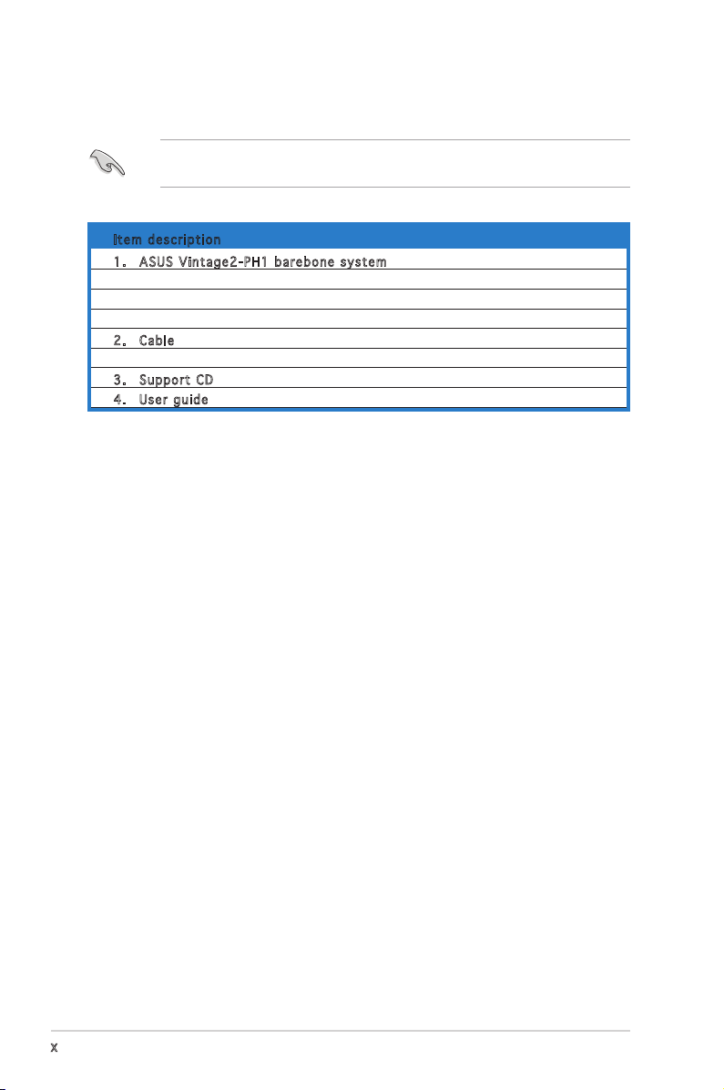
System package contents .................................................................... x
Chapter 1: System Introduction
1.1 Welcome! .............................................................................. 1-2
1.2 Front panel .......................................................................... 1-2
1.3 Rear panel ............................................................................. 1-4
Voltage selector ................................................................... 1-6
1.4 Internal components ............................................................. 1-7
Chapter 2: Basic Installation
2.1 Preparation ........................................................................... 2-2
2.2 Before you proceed .............................................................. 2-2
2.3 Removing the side cover and front panel assembly ............. 2-3
2.4 Central Processing Unit (CPU) .............................................. 2-4
2.4.1 Overview ................................................................. 2-4
2.4.2 Installing CPU .......................................................... 2-4
2.4.3 Installing the CPU fan and heatsink assembly ......... 2-6
2.5 Installing a DIMM ................................................................... 2-8
2.5.1 Memory configurations ........................................... 2-8
2.5.2 Installing a DDR2 DIMM ........................................... 2-9
2.5.3 Removing a DDR2 DIMM .......................................... 2-9
2.6 Expansion slots ................................................................... 2-10
2.6.1 Installing an expansion card .................................. 2-10
2.6.2 Configuring an expansion card .............................. 2-10
2.6.3 PCI Express x1 slot ............................................... 2-12
2.6.4 PCI slots ................................................................ 2-12
2.6.5 PCI Express x16 slot ............................................. 2-12
2.7 Installing an optical drive .................................................... 2-13
2.8 Installing a hard disk drive .................................................. 2-15
2.9 Installing a floppy disk drive ............................................... 2-18
2.10 Re-connecting cables .......................................................... 2-19
LED cables .......................................................................... 2-19
2.11 Removing the bay covers and reinstalling the front panel
assembly and side cover ..................................................... 2-20

iv
Table of contents
Chapter 3: Starting up
3.1 Installing an operating system .............................................. 3-2
3.2 Powering up .......................................................................... 3-2
3.3 Support CD information ........................................................ 3-2
3.3.1 Running the support CD .......................................... 3-3
3.3.2 Utilities menu .......................................................... 3-4
3.2.3 Manuals menu ......................................................... 3-5
3.3.4 ASUS Contact information ...................................... 3-6
3.4 Software information ............................................................ 3-7
3.4.1 ASUS Update ........................................................... 3-7
3.4.2 ASUS PC Probe II ..................................................... 3-9
Chapter 4: Motherboard Info
4.1 Introduction .......................................................................... 4-2
4.2 Motherboard layout .............................................................. 4-2
4.3 Jumpers ................................................................................ 4-3
4.4 Connectors ........................................................................... 4-4
Chapter 5: BIOS Information
5.1 Managing and updating your BIOS ........................................ 5-2
5.1.1 Creating a bootable floppy disk .............................. 5-2
5.1.2 ASUS EZ Flash utility ............................................... 5-3
5.1.3 AFUDOS utility ........................................................ 5-4
5.1.4 ASUS CrashFree BIOS 2 utility ................................ 5-6
5.1.5 ASUS Update utility ................................................ 5-8
5.2 BIOS setup program ............................................................ 5-11
5.2.1 BIOS menu screen ................................................. 5-12
5.2.2 Menu bar ............................................................... 5-12
5.2.3 Navigation keys ..................................................... 5-12
5.2.4 Menu items ........................................................... 5-13
5.2.5 Sub-menu items .................................................... 5-13
5.2.6 Configuration fields ............................................... 5-13
5.2.7 Pop-up window ...................................................... 5-13
5.2.8 Scroll bar ............................................................... 5-13
5.2.9 General help .......................................................... 5-13

v
Table of contents
5.3 Main menu ........................................................................... 5-14
5.3.1 System Time ........................................................ 5-14
5.3.2 System Date ........................................................ 5-14
5.3.3 Legacy Diskette A ............................................... 5-14
5.3.4 Primary, Third and Fourth IDE Master/Slave ......... 5-15
5.3.5 IDE Configuration .................................................. 5-16
5.3.6 System Information .............................................. 5-18
5.4 Advanced menu .................................................................. 5-19
5.4.1 JumperFree Configuration ..................................... 5-19
5.4.2 USB Configuration ................................................. 5-22
5.4.3 CPU Configuration ................................................. 5-23
5.4.4 Chipset .................................................................. 5-25
5.4.5 Onboard Devices Configuration ............................. 5-26
5.4.6 PCI PnP .................................................................. 5-28
5.5 Power menu ........................................................................ 5-29
5.5.1 Suspend Mode ....................................................... 5-29
5.5.2 ACPI 2.0 Support ................................................. 5-29
5.5.3 ACPI APIC Support ............................................... 5-29
5.5.4 APM Configuration ................................................ 5-30
5.5.5 Hardware Monitor .................................................. 5-32
5.6 Boot menu .......................................................................... 5-34
5.6.1 Boot Device Priority .............................................. 5-34
5.6.2 Boot Settings Configuration ................................. 5-35
5.6.3 Security ................................................................. 5-36
5.7 Exit menu ............................................................................ 5-38

vi
Notices
Federal Communications Commission Statement
This device complies with Part 15 of the FCC Rules. Operation is subject to
the following two conditions:
•
This device may not cause harmful interference, and
•
This device must accept any interference received including
interference that may cause undesired operation.
This equipment has been tested and found to comply with the limits for a
Class B digital device, pursuant to Part 15 of the FCC Rules. These limits
are designed to provide reasonable protection against harmful interference
in a residential installation. This equipment generates, uses and can radiate
radio frequency energy and, if not installed and used in accordance with
manufacturerʼs instructions, may cause harmful interference to radio
communications. However, there is no guarantee that interference will
not occur in a particular installation. If this equipment does cause harmful
interference to radio or television reception, which can be determined by
turning the equipment off and on, the user is encouraged to try to correct
the interference by one or more of the following measures:
•
Reorient or relocate the receiving antenna.
•
Increase the separation between the equipment and receiver.
•
Connect the equipment to an outlet on a circuit different from that to
which the receiver is connected.
•
Consult the dealer or an experienced radio/TV technician for help.
Canadian Department of Communications Statement
This digital apparatus does not exceed the Class B limits for radio noise
emissions from digital apparatus set out in the Radio Interference
Regulations of the Canadian Department of Communications.
This class B digital apparatus complies with Canadian ICES-003.
WARNING! The use of shielded cables for connection of the monitor to
the graphics card is required to assure compliance with FCC regulations.
Changes or modifications to this unit not expressly approved by the
party responsible for compliance could void the userʼs authority to
operate this equipment.

vii
Safety information
Electrical safety
•
To prevent electrical shock hazard, disconnect the power cable from
the electrical outlet before relocating the system.
•
When adding or removing devices to or from the system, ensure that
the power cables for the devices are unplugged before the signal cables
are connected.
•
If the power supply is broken, do not try to fix it by yourself. Contact a
qualified service technician or your retailer.
Operation safety
•
Before installing devices into the system, carefully read all the
documentation that came with the package.
•
Before using the product, make sure all cables are correctly connected
and the power cables are not damaged. If you detect any damage,
contact your dealer immediately.
•
To avoid short circuits, keep paper clips, screws, and staples away from
connectors, slots, sockets and circuitry.
•
Avoid dust, humidity, and temperature extremes. Do not place the
product in any area where it may become wet. Place the product on a
stable surface.
•
If you encounter technical problems with the product, contact a
qualified service technician or your retailer.
Lithium-Ion Battery Warning
CAUTION: Danger of explosion if battery is incorrectly replaced.
Replace only with the same or equivalent type recommended by
the manufacturer. Dispose of used batteries according to the
manufacturerís instructions.
VORSICHT: Explosionsgetahr bei unsachgemäßen Austausch der
Batterie. Ersatz nur durch denselben oder einem vom Hersteller
empfohlenem ähnljchen Typ. Entsorgung gebrauchter Batterien nach
Angaben des Herstellers.
LASER PRODUCT WARNING
CLASS 1 LASER PRODUCT

viii
About this guide
Audience
This guide provides general information and installation instructions about
the ASUS Vintage2 - PH1 barebone system. This guide is intended for
experienced users and integrators with hardware knowledge of personal
computers.
How this guide is organized
This guide contains the following parts:
1. Chapter 1: System introduction
This chapter gives a general description of the ASUS Vintage 2 - PH1.
The chapter lists the system features, including introduction on the
front and rear panel, and internal components.
2. Chapter 2: Basic installation
This chapter provides step-by-step instructions on how to install
components in the system.
3. Chapter 3: Starting up
This chapter helps you power up the system and install drivers and
utilities from the support CD.
4. Chapter 4: Motherboard information
This chapter gives information about the motherboard that comes
with the system. This chapter includes the motherboard layout,
jumper settings, and connector locations.
5. Chapter 5: BIOS information
This chapter tells how to change system settings through the BIOS
Setup menus and describes the BIOS parameters.

ix
Conventions used in this guide
WARNING: Information to prevent injury to yourself when
trying to complete a task.
CAUTION: Information to prevent damage to the components
when trying to complete a task.
IMPORTANT: Instructions that you MUST follow to complete a
task.
NOTE: Tips and additional information to aid in completing a
task.
Where to find more information
Refer to the following sources for additional information and for product
and software updates.
1. ASUS Websites
The ASUS websites worldwide provide updated information on
ASUS hardware and software products. Refer to the ASUS contact
information.
2. Optional Documentation
Your product package may include optional documentation, such as
warranty flyers, that may have been added by your dealer. These
documents are not part of the standard package.

x
System package contents
Check your Vintage2-PH1 system package for the following items.
If any of the items is damaged or missing, contact your retailer
immediately.
Item description
1. ASUS Vintage2-PH1 barebone system with
• ASUS motherboard
• 300 W PFC power supply unit
• ASUS chassis
2. Cable
• AC power cable
3. Support CD
4. User guide

ASUS Vintage2-PH1
Chapter 1
System introduction
This chapter gives a general
description of the ASUS
Vintage2-PH1. The chapter lists
the system features including
introduction on the front and rear
panel, and internal components.

1-2 Chapter 1: System introduction
1.1 Welcome!
Thank you for choosing the ASUS Vintage2-PH1!
The ASUS Vintage2-PH1 is an all-in-one barebone system with a versatile
home entertainment feature.
The system comes in a stylish mini-tower casing and powered by the ASUS
motherboard that supports the Intel® Pentium® D, Intel® Pentium® 4 or
Intel® Celeron® processor in the 775-land package.
The system supports up to 4 GB of system memory using DDR2-600/
DDR2-533 DIMMs, high-resolution graphics via integrated graphics
controller or PCI Express x16 slot, Serial ATA, USB 2.0, and 6-channel
audio features the system takes you ahead in the world of power
computing.
1.2 Front panel
The front panel includes the optical drive bays, floppy disk drive slot, power
button, and several I/O ports are located at the front panel.
1
3
2
4
567
8
9

1-3
ASUS Vintage2-PH1
1. Two empty 5.25-inch bays. These bays are for IDE optical drives.
2. 3.5-inch drive bays. This slot is for a 3.5-inch floppy or hard disk
drive. (The floppy disk drive is included in the package.)
3. IEEE 1394 port. This 6-pin IEEE 1394a port provides high-speed
connectivity for audio/video devices, storage peripherals, PCs, or
protable devices.
4. Power button. Press this button to turn the system on.
5. Reset button. Press this button to reboot the system without
turning off the power.
6. HDD LED. This LED lights up when data is read from or written to the
hard disk drive.
7. USB 2.0 ports. These Universal Serial Bus 2.0 (USB 2.0) ports are
available for connecting USB 2.0 devices such as a mouse, printer,
scanner, camera, PDA, and others.
8. Headphone port. This Line In (green) port connects a headphone
with a stereo mini-plug.
9. Microphone port. This Mic (pink) port connects a microphone.

1-4 Chapter 1: System introduction
1.3 Rear panel
The system rear panel includes the power connector and several I/O ports
that allow convenient connection of devices.
1. Power connector. This connector is for the power cable and plug.
2. Voltage selector. This switch allows you to adjust the system input
voltage according to the voltage supply in your area. See the “Voltage
selector” section on page 1-6 before adjusting this switch.
3. PS/2 mouse port. This green 6-pin connector is for a PS/2 mouse.
4. PS/2 keyboard port. This purple 6-pin connector is for a
PS/2 keyboard.
5. Serial port . This port connects a mouse, modem, or other devices
that conforms with serial specification.
REAR
S P K
LINE
IN
FRONT
MIC IN
SIDE
S P K
C T R
BASS
10
12
11
14
16
1
2
4
5
6
7
8
9
3
13
17
18
19
15

1-5
ASUS Vintage2-PH1
6. Parallel port. This 25-pin port connects a printer, scanner, or
other devices.
7. VGA port. This port connects a VGA monitor.
8. USB 2.0 ports 1, 2, 3 and 4. These 4-pin Universal Serial Bus
(USB) ports are available for connecting USB 2.0 devices.
9. Side Speaker Out port (black). This port connects the side
speakers in an 8-channel audio configuration.
10. Rear Speaker Out port (orange). This port connects the rear
speakers on a 4-channel, 6-channel, or 8-channel audio configuration.
11. Microphone port (pink). This port connects a microphone.
12. Line Out port (lime). This port connects a headphone or a
speaker. In 4-channel, 6-channel, and 8-channel configuration, the
function of this port becomes Front Speaker Out.
13. Line In port (Light blue). This port connects the tape, CD, DVD
player, or other audio sources.
14. Power supply unit fan vent. This vent is for the PSU fan that
provides ventilation inside the power supply unit.
15. Chassis fan vent. This vent is for the fan that provides ventilation
inside the system chassis.
16. IEEE 1394a port. This 6-pin IEEE 1394 port provides high-speed
connectivity for audio/vidoe devices, storage peripherals, PCs, or
portable devices.
17. LAN (RJ-45) port. This port allows Gigabit connection to a Local
Area Network (LAN) through a network hub.
18. Center/Subwoofer port (gray). This port connects the center/
subwoofer speakers.
19. Expansion slot covers. Remove these covers when installing
expansion cards.
Refer to the audio configuration table below for the function of the audio
ports in 2, 4, 6, or 8-channel configuration.
Audio 2, 4, 6, or 8-channel configuration
Light Blue Line In Line In Line In Line In
Lime Line Out Front Speaker Out Front Speaker Out Front Speaker Out
Pink Mic In Mic In Mic In Mic In
Orange • Rear Speaker Out Rear Speaker Out Rear Speaker Out
Black • • • Side Speaker Out
Gray • • Center/Subwoofer Center/Subwoofer
Port Headset 4-channel 6-channel 8-channel
2-channel

1-6 Chapter 1: System introduction
Voltage selector
The PSU has a 115 V/230 V voltage selector switch located beside the
power connector. Use this switch to select the appropriate system input
voltage according to the voltage supply in your area.
If the voltage supply in your area is 100-127 V, set this switch to 115 V.
If the voltage supply in your area is 200-240 V, set this switch to 230 V.
Setting the switch to 115V in a 230V environment or 230V in a 115V
environment will seriously damage the system!
115V/230V
Voltage selector

1-7
ASUS Vintage2-PH1
1.4 Internal components
The illustration below is the internal view of the system when you remove
the top cover and the power supply unit. The installed components are
labeled for your reference. Proceed to Chapter 2 for instructions on
installing additional system components.
CR2032 3V
Lithium Cell
CMOS Power
CD
Super
I/O
Intel FWH
4Mb
ATX12V
FLOPPY
AAFP
DDR DIMM_A1 (64 bit,240-pin module)
SB_PWR
F_PANEL
CHASSIS
USB78
USB56
CLRTC
PCI1
Intel®
GMCH
945G
Intel®
ICH7
DDR DIMM_A2 (64 bit,240-pin module)
DDR DIMM_B1 (64 bit,240-pin module)
DDR DIMM_B2 (64 bit,240-pin module)
CHA_FAN
CPU_FAN
PRI_IDE
EATXPWR
PCI2
SPDIF_OUT
Intel
82573L
PS/2KBMS
T: Mouse
B: Keyboard
PCIEX1_1
PCIEX16
COM1
PARALLEL PORT
VGA
PLED
®
SATA1 SATA2
SATA4SATA3
BUZZ
PWR_FAN
SPEAKER
COM2
ALC882
TI
TSB43AB22A
IE1394_2
LGA775
LAN_USB34
AUDIO
USB1
USB2
Bottom:
1394
Top:
1. Front panel cover
2. 5.25-inch optical drive bays
3. Hard disk drive bay
4. Floppy disk drive bay
5. Power supply unit
6. CPU socket
7. DIMM sockets
8. ASUS motherboard
9. Chassis fan
10. PCI Express x16 slot
11. PCI slots
12. PCI Express x1 slot
13. Metal bracket lock
61
2
3
4
13 11
97
8
5
12
10

1-8 Chapter 1: System introduction

ASUS Vintage2-PH1
Chapter 2
Basic installation
This chapter provides step-by-
step instructions on how to install
components in the system.

2-2 Chapter 2: Basic installation
2.1 Preparation
Before you proceed, make sure that you have all the components you plan
to install in the system.
Basic components to install
1. Central processing unit (CPU)
2. DDR Dual Inline Memory Module (DIMM)
3. Expansion card(s)
4. Hard disk drive
5. Optical drive
6. Floppy disk drive
Tool
Phillips (cross) screw driver
The motherboard comes with an onboard standby power LED. This LED
lights up to indicate that the system is ON, in sleep mode or in soft-off
mode, and not powered OFF. Unplug the power cable from the power outlet
and make sure that the standby power LED is OFF before installing any
system component.
•
Use a grounded wrist strap or touch a safely grounded object or
a metal object, such as the power supply case, before handling
components to avoid damaging them due to static electricity.
•
Hold components by the edges to avoid touching the ICs on them.
•
Whenever you uninstall any component, place it on a grounded
antistatic pad or in the bag that came with the component.
2.2 Before you proceed
Take note of the following precautions before you install components into
the system.
®
Onboard LED
SB_PWR
ON
Standby
Power
OFF
Powered
Off
Other manuals for V2-PH1
1
This manual suits for next models
1
Table of contents
Other Asus Desktop manuals

Asus
Asus Pundit-PH3 User manual

Asus
Asus FX10CP User manual

Asus
Asus P Series User manual

Asus
Asus PL64 Series User manual

Asus
Asus PE100A User manual

Asus
Asus AAEON BOXER-6710 User manual

Asus
Asus Terminator 2 User manual

Asus
Asus V221 Series User manual

Asus
Asus ET2221INKH User manual

Asus
Asus ESC2000 User manual