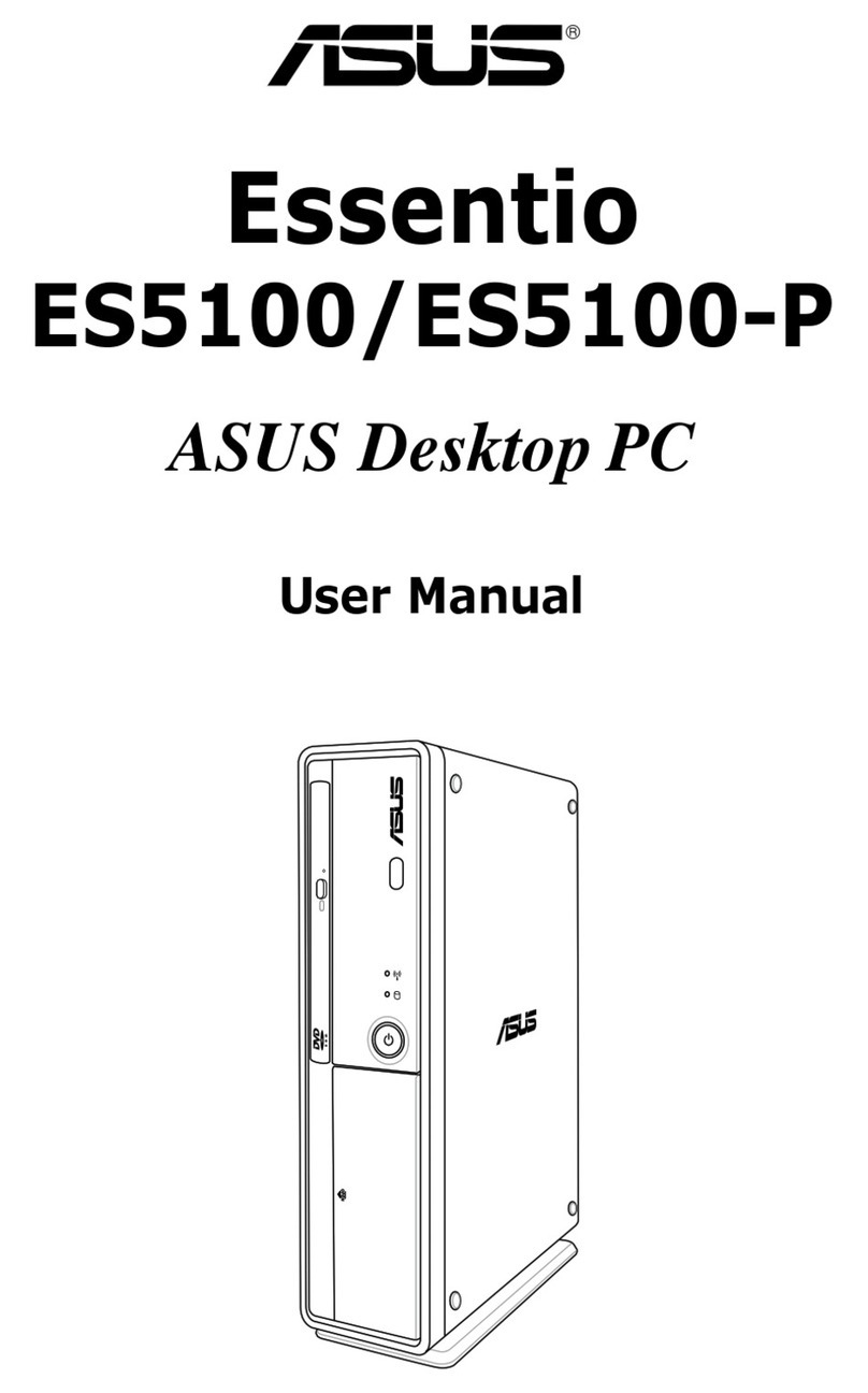
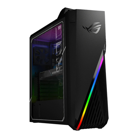
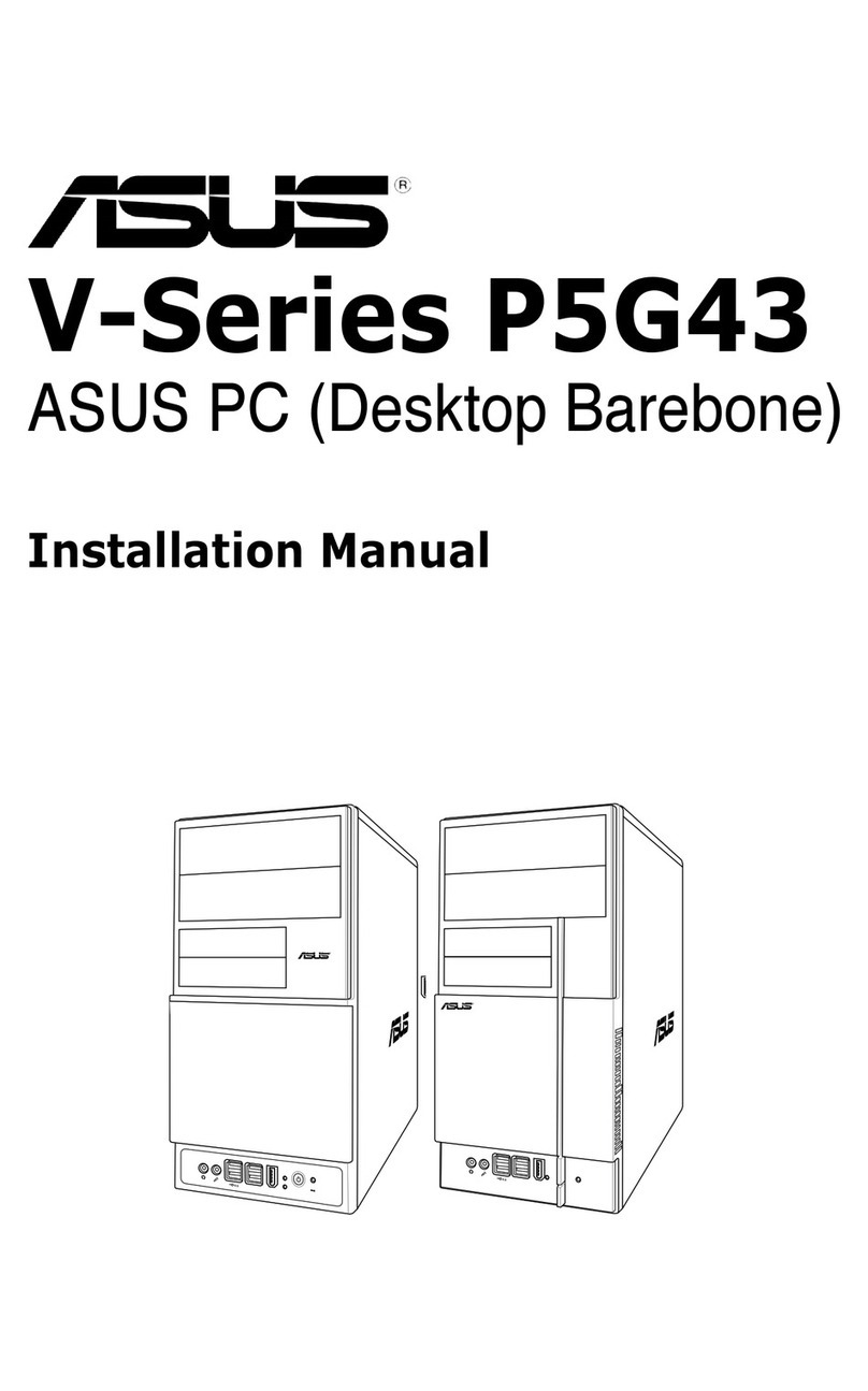
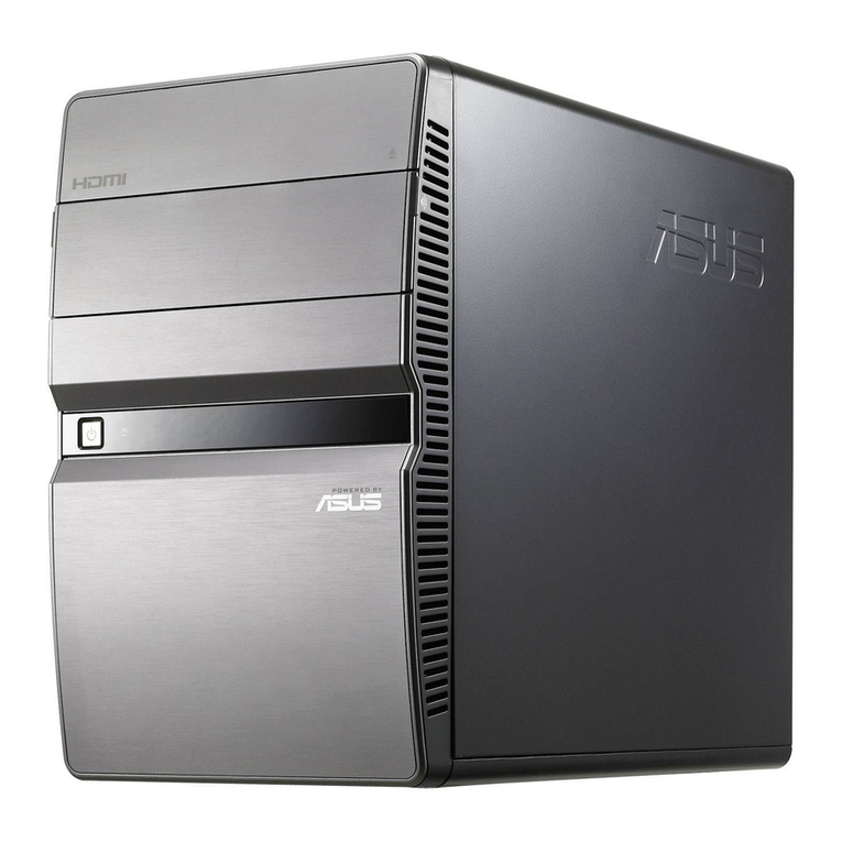
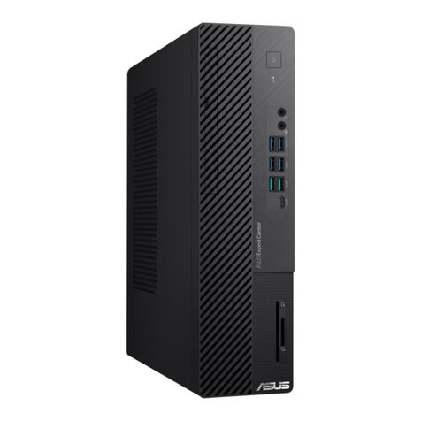
Asus V6 Series User manual

English
V6-Series
V7-Series
V9-Series
ASUS PC (Desktop Barebone)
Installation manual
R
U6085

2Installation manual
English
Front panel features
1. 5.25-inch drive bay cover
2. 3.5-inch drive bay cover
3. Headphone portHeadphone port
4. Microphone portMicrophone port
5. USB 2.0 ports (2 or 4 USB ports vary with models)USB 2.0 ports (2 or 4 USB ports vary with models)
6. Power button
7. Card reader LED
8. CompactFlash®/Microdrive™ card slot
9. Secure Digital™/Multimedia Card slot
10. MemoryStick®/ Memory Stick Pro™ card slot™ card slotcard slot
11. IEEE 1394a port (optional)
12. Eject button
R
6
5
3 4
1
2
V6 Series Front Panel
6
5
11
1
V7 Series Front Panel
8
10
9
4 3
7
5
12
10
4
6
3
9
1
8
V9 Series Front Panel

3
Installation manual
English
Rear panel features
NOTE: The rear panel ports and their locations
may vary, depending on the model of your
system. For detailed descriptions, refer to the
system User Guide.
1. PS/2 keyboard port ( )
2. PS/2 mouse port ( )
3. VGA port ( )
4. USB 2.0 ports ( )
(some models may
have four rear USB 2.0 ports)
5. One of the following ports:
• Optical S/PDIF Out port ( )
• Coaxial S/PDIF Out port ( )
6. IEEE 1394a port ( )
(some models only)
7. LAN (RJ-45) port ( )
8. One of the following ports:
• E-SATA port ( )
• Serial (COM1) port ( )
• DVI port ( )
• HDMI port ( )
9. Oneofthefollowingaudioportscongurations:
• 6-channel • 8-channel
RefertothecongurationtableintheUserGuidefordetails.
1 2
3
8
9

4Installation manual
English
Internal components
1. Front panel cover
2. 5.25-inch optical drive bays
3. 2.5-inch portable hard disk drive bay
(optional)
4. Hard disk drive bay
5. Power supply unit
6. Chassis fan slot
7. ASUS motherboard*
8. Expansion slot metal brackets
9. 3.5-inch hard disk drive holder
(optional)
NOTE: *Refer to the system User Guide for motherboard details.
1
3
4
5
6
2
8
7
9

5
Installation manual
English
Selecting the voltage
The system’s power supply unit has a 115
V/230 V voltage selector switch located
beside the power connector. Use this
switch to select the appropriate system
input voltage according to the voltage
supply in your area.
If the voltage supply in your area is
100-127 V, set the switch to 115 V.
If the voltage supply in your area is
200-240 V, set the switch to 230 V.
Removing the side cover and
front panel assembly
1. Remove the cover screws on the rear panel.
2. Pull the side cover toward the rear panel until its hooks disengage from the
chassis tab holes. Set the side cover aside.
3. Locate the front panel assembly hooks, then lift them until they disengage
from the chassis.
4. Swing the front panel assembly to the right, until the hinge-like tabs on the
right side of the assembly are exposed.
5. Remove the front panel assembly, then set aside.
Air ductduct
1
1
2
24
34
4
3
3
4
Chassis tab holes
NOTE: Refer to the system User Guide for the exact location of the voltage selector.

6Installation manual
English
Installing a CPU
CAUTION! To prevent damage to
the socket pins, do not remove the
PnP cap unless you are installing
a CPU.
Installing an Intel®CPU in the LGA775 package
1. Locate the CPU socket on the motherboard.
2. Press the load lever with your thumb
(A), then move it to the left (B) until it
is released from the retention tab.
3. Lift the load lever in the direction of the arrow to
a 135º angle.
4. Lift the load plate with your thumb and
forengertoa100ºangle(4A),thenpushthe
PnP cap from the load plate window to remove
(4B).
Gold
triangle
mark
Alignment key
Load lever
Retention tab
A
B
Load plate
PnP cap
4B 4A
B
A
5. Position the CPU over the socket, making
sure that the gold triangle is on the bottom-left
corner of the socket. Fit the socket alignment
key into the CPU notch.
6. Close the load plate (A), then push the load
lever (B) until it snaps into the retention tab.
3

7
Installation manual
English
Installing an Intel®CPU in the LGA1156 package
1. Locate the CPU socket on the motherboard.
To prevent damage to the socket pins, do
not remove the PnP cap unless you are
installing a CPU.
2. Press the load lever with your thumb (A),
and then move it to the right (B) until it is
released from the retention tab.
A
B
Load lever
Retention tab
3. Lift the load lever in the direction of the
arrow until the load plate is completely lifted.
Load plate
4. Remove the PnP cap from the CPU
socket by lifting the tab only.
TheCPUtsinonlyonecorrect
orientation. DO NOT force the CPU
into the socket to prevent bending the
connectors on the socket and damaging
the CPU!
Gold
triangle
mark
Alignment keys
CPU notches
5. Position the CPU over the socket,
ensuring that the gold triangle is on the
bottom-left corner of the socket, and then
tthesocketalignmentkeysintothe
CPU notches.
PnP cap
Cap tab

8Installation manual
English
7. Close the load plate (A), and then push
down the load lever (B), ensuring that
the front edge of the load plate slides
under the retention knob (C).
B
A
C
8. Insert the load lever under the
retention tab.
6. Apply some Thermal Interface Material
to the exposed area of the CPU that the
heatsink will be in contact with, ensuring
that it is spread in an even thin layer.
Some heatsinks come with pre-applied
thermal paste. If so, skip this step.
The Thermal Interface Material is toxic
and inedible. DO NOT eat it. If it gets into
your eyes or touches your skin, wash it
off immediately, and seek professional
medical help.

9
Installation manual
English
Installing the CPU fan and heatsink assembly
Installing an Intel®CPU heatsink and fan
1. Place the heatsink on top of the installed
CPU, making sure that the four fasteners
match the holes on the motherboard.
2. Push down two fasteners at a time in a
diagonal sequence to secure the heatsink
and fan assembly in place.
3. When the fan and heatsink assembly is in
place, connect the CPU fan cable to the
connector on the motherboard.
Installing an AMD CPU
1. Locate the CPU socket, then lift the socket lever to a 90º angle.
2. Install the CPU to the socket, making sure that the CPU corner with the gold
triangle matches the socket corner with a small triangle.
3. Push down the socket lever to secure the CPU.
CAUTION: Incorrect installation of the CPU into the socket may bend the pins and
severely damage the CPU!
1 2 3
A
B
B
A
1
1

10 Installation manual
English
Installing an AMD CPU heatsink and fan
1. Place the heatsink on top of the installed CPU.
IMPORTANT.Makesurethatthefanandheatsinkassemblyperfectlytstheretention
mechanism module base; otherwise you can not lock the retention bracket.
2. Attach one end of the retention bracket to the retention module base.
3. Attach the other end of the retention bracket (near the retention bracket lock)
to the retention module base until it clicks in place.
NOTE. Your boxed CPU should come with installation instructions for the CPU, fan/heatsink
assembly, and the retention mechanism. If the instructions in this section do not match the
CPU documentation, follow the latter.
4. Push down the retention bracket lock on the retention mechanism to secure
the fan and heatsink to the module retention module base.
5. Connect the CPU fan cable to the connector on the motherboard.
CAUTION. Do not forget to connect the CPU fan connector! Hardware monitoring error
can occur if you fail to plug this connector.
Retention module base
CPU heatsink
CPU fan
Retention
bracket lock
Retention bracket
CPU fan
connector
2
1
5
3
4

11
Installation manual
English
Installing an expansion card
2. Remove the metal bracket lock.1. Remove the metal cover opposite
the slot that you intend to use.
3. Insert the card connector to the
slot,thenpressthecardrmly
untilittsinplace.
4. Replace the metal bracket lock.
Installing a DIMM
1. Locate the DIMM sockets in the motherboard.
2. Unlock a DIMM socket by pressing the retaining clips outward.
3. Align a DIMM on the socket such that the notch on the DIMM matches the
break on the socket.
4. Push the DIMM to the socket until the retaining clips snap inward.
CAUTION:
• Unplug the power supply before adding or removing DIMMs. Failure to do so may
cause damage to the motherboard and/or components.
• ADDR2/DDR3DIMMiskeyedwithanotchsothatittsinonlyonedirection.
Do not force a DIMM into a socket in the wrong direction to avoid damaging the
DIMM.
1
2
3
4

12 Installation manual
English
Hard disk drive
1. Remove the 3.5-inch hard drive holder out of the chassis.
NOTE: The 3.5-inch hard drive holder is optional.
2. Insert the hard disk drive to the 3.5-inch hard drive holder, then carefully push
the drive until its screw holes align with the holes on the holder.
Installing storage drives
Optical drive
1. Place the chassis upright, then
remove the upper 5.25” drive bay
metal plate cover.
2. Insert the optical drive to the bay, then
carefully push the drive until its screw
holes align with the holes on the bay.
3. Secure the optical drive with two screws on both sides of the bay.
4. For SATA ODD: Connect the SATA
signal and power plugs to the
connectors at the back of the drive.
For IDE ODD: Connect the IDE and
power plugs to the connectors at the
back of the drive.
Floppy disk drive
If the system comes without a portable hard disk (optional), then you may install a
oppydiskdriveintothe3.5-inchdrivebay.
1. Place the chassis upright, then
remove the upper 3.5” drive bay metal
plate cover.
2. Inserttheoppydiskdrivetothebay,
then carefully push the drive until its
screw holes align with the holes on the
bay.
3. Securetheoppydiskdrivewithtwo
screws on both sides of the bay.
4. Connect the signal (A) and power (B)
plugs to connectors at the back of the
drive.
2
3
3
2
3
3
A
B
SATA IDE
4

13
Installation manual
English
3. Secure the hard disk drive with two
screws on both sides of the bay.
4. Replace the hard drive holder to the
chassis and secure the screws.
5. For SATA HDD: Connect the SATA
signal and power plugs to the
connectors at the back of the drive.
For IDE HDD: Connect the IDE and
power plugs to the connectors at the
back of the drive.
Reinstalling the front panel assembly and
side cover
To reinstall the front panel assembly and side cover:
1. Insert the front panel assembly hinge-like tabs to the holes on the right side
of the chassis.
2. Swing the front panel assembly to the left, then insert the hooks to the
chassisuntilthefrontpanelassemblytsinplace.
3. Insert the six side cover hooks into the chassis tab holes .
4. Pushthesidecovertothedirectionofthefrontpaneluntilittsinplace.
5. Secure the cover with two screws you removed earlier.
SATA IDE
Air duct
5
5
3
4
1
21
1
2
2
2
Chassis tab holes
2
3
3

Français
V6-Series
V7-Series
V9-Series
ASUS PC (Système Barebone)
Manuel d’installation
R
QF6085

15
Manuel d’installation
Français
Caractéristiques de la façade
1. Cache pour baies 5.25”
2. Cache pour baies 3.5”
3. Prise casque
4. Prise micro
5. Ports USB 2.0 (2 ou 4 ports USB en fonction du modèle)
6. Bouton d’alimentation
7. Récepteur infrarouge*
8. Fente pour cartes mémoire CompactFlash®/Microdrive™
9. Fente pour cartes mémoire Secure Digital™/Multimedia
10. Fente pour cartes mémoire MemoryStick®/ Memory Stick Pro™
11. Port IEEE 1394a (optionnel)
12. Bouton d’éjection
R
6
5
3 4
1
2
Façade Séries V6 Façade Séries V7
5
12
10
4
6
3
9
1
8
Façade Séries V9
6
5
11
1
8
10
9
4 3
7

16 Manuel d’installation
Français
Caractéristiques du panneau l’arrière
REMARQUE : Les ports du panneau arrière
ainsi que leur emplacement peuvent varier selon
votre système. Pour une description détaillée,
reportez-vous au manuel de l’utilisateur de votre
système.
1. Port clavier PS/2 ( )
2. Port souris PS/2 ( )
3. Port VGA ( )
4. Ports USB 2.0 ( )
(certains modèles
peuvent intégrer quatre ports USB 2.0)
5. Un des ports suivants :
• Port S/PDIF Out optique ( )
• Port S/PDIF Out coaxial ( )
6. Port IEEE 1394a ( )
(sur une sélection
de modèles)
7. Port réseau (RJ-45) ( )
8. Un des ports suivants :
• Port E-SATA ( )
• Port Série (COM1) ( )
• Port DVI ( )
• Port HDMI ( )
9. Unedescongurationsdeportsaudiosuivantes:
• 6 canaux • 8 canaux
Reportez-vousautableaudecongurationcontenudanslemanuelde
l’utilisateur pour plus de détails.
1 2
3
8
9

17
Manuel d’installation
Français
Composants internes
1. Capot de la façade
2. Baie 5.25 pouces pour lecteur
optique
3. Baie pour lecteur de disque dur
portable de 2.5” (optionnel)
4. Baie pour disque dur
5. Unité d’alimentation
6. Emplacement pour ventilateur
châssis
7. Carte mère ASUS*
8. Supports métalliques pour slots
d’extension
9. Cage pour disque dur de 3.5”
(optionnel)
REMARQUE : *Reportez-vous au manuel de l’utilisateur du système pour plus de
détails sur la carte mère.
1
3
4
5
6
2
8
7
9

18 Manuel d’installation
Français
Sélection du voltage
L’alimentation du système est équipée
d’un sélecteur de tension 115 V/230 V
situé près du connecteur d’alimentation.
Utilisez cet interrupteur pour choisir la
bonne tension d’entrée en fonction des
standards utilisés dans votre région.
Si la tension dans votre région est de
100-127 V, passez l’interrupteur sur 115 V.
Si la tension dans votre région est de
200-240 V, passez l’interrupteur sur 230 V.
Retirer le panneau latéral et la façade
1. Retirez les vis du panneau arrière.
2. Faites glisser le panneau latéral vers l’arrière jusqu’à ce que ses crochets se
détachent des onglets du châssis. Mettez le panneau latéral de côté.
3. Repérez les crochets de la façade, et soulevez-les jusqu’à ce qu’ils se
détachent du châssis.
4. Faites pivoter la façade vers la droite, jusqu’à ce que les clapets situés sur le
côté droit du panneau soient visibles.
5. Retirez la façade, puis mettez-la de côté.
Gaine
d’aération
1
1
2
24
34
4
3
3
4
Onglets du châssis
REMARQUE : Reportez-vous au manuel de l’utilisateur du système pour
l’emplacement exacte du sélecteur de voltage.

19
Manuel d’installation
Français
Installer un processeur
ATTENTION: Pour éviter
d’endommager les broches du
socket, ne retirez pas le cache
PnP sauf pour installer le CPU.
Installer un processeur Intel®au format LGA775
1. Localisez le socket du CPU sur la carte mère.
2. Pressez le levier avec votre pouce
(A) et glissez-le vers la gauche (B)
jusqu’à ce qu’il soit libéré du loquet
de rétention.
3. Levezlelevierdansladirectiondelaècheà
un angle de 135º.
4. Levez la plaque avec votre pouce à un angle de
100°(4A), puis poussez le couvercle PnP de la
plaque pour l’enlever (4B).
Marque
triangulaire
dorée
Clef d’alignement
Levier
Onglet de rétention
A
B
Plaque de
chargement
Cache PnP
4B 4A
B
A
5. Placez le CPU au dessus du socket, en vous
assurant que le triangle doré soit dans le coin
inférieur gauche du socket. La clef d’alignement
du socket doit correspondre avec l’encoche du
CPU.
6. Refermez la plaque (A), puis poussez le levier
(B) jusqu’à ce qu’il soit accroché par le loquet
de rétention.
3

20 Manuel d’installation
Français
Installer un processeur Intel®au format LGA1156
1. Localisez le socket du CPU sur la carte mère.
Pour éviter d’endommager les broches
du socket, n’enlevez le couvercle PnP
que pour installer un CPU.
2. Pressez le levier avec votre pouce (A)
et déplacez-le vers la droite (B) jusqu’à
ce qu’il soit libéré de son onglet de
rétention.
A
B
Levier
Onglet de rétention
3. Soulevez le levier dans la direction de
laèchejusqu’àcequelaplaquede
chargement soit complètement ouverte.
Plaque de
chargement
4. Enlevez le cache PnP du socket
CPU en soulevant l’onglet.
Le CPU ne peut être placé que dans un
seul sens. NE FORCEZ PAS sur le CPU
pour le faire entrer dans le socket pour
éviter de plier les broches du socket et/ou
d’endommager le CPU !
Triangle
doré
Ergots
d’alignement
Encoches du CPU
5. Placez le CPU sur le socket, en vous
assurant que la marque en forme de
triangle doré est placée en bas à gauche
du socket. Les ergots d’alignement sur
le socket doivent correspondre aux
encoches du CPU.
Cache PnP
Onglet
Other manuals for V6 Series
3
This manual suits for next models
2
Table of contents
Languages:
Other Asus Desktop manuals

Asus
Asus BM6635 User manual

Asus
Asus V222F Series User manual

Asus
Asus S2-P8H61E User manual

Asus
Asus D700SA User manual

Asus
Asus T4-P5945GCX User manual

Asus
Asus G13CH User manual

Asus
Asus V222F Series User manual

Asus
Asus V-Series P5G965 User manual

Asus
Asus V6-P7H55E User manual

Asus
Asus Eee Box B202 User manual

Asus
Asus G1-P7P55E User manual

Asus
Asus Essentio CM1831 User manual

Asus
Asus G20CB User manual

Asus
Asus V2-P5945G User manual

Asus
Asus GL12CP User manual

Asus
Asus Aaeon GENESYS-WHU6 User manual

Asus
Asus ET2702IGKH User manual

Asus
Asus V2-P5945GC User manual

Asus
Asus BM1AD User manual

Asus
Asus AAEON RTC-710AP User manual