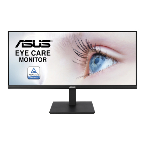
Asus VK266H - 25.5" LCD Monitor User manual

Service Manual ASUS VK266H&VW266H
LCD Monitor Service Manual
Model: ASUS VK266H
Model: ASUS VW266H
D
SPECIFICATIONS AND INFORMATION CONTAINED IN THIS MANUAL ARE FURNISHED FOR
INFORMATIONAL USE ONLY, AND ARE SUBJECT TO CHANGE AT ANY TIME WITHOUT NOTICE, AND
SHOULD NOT BE CONSTRUED AS A COMMITMENT BY ASUS. ASUS ASSUMES NO RESPONSIBILITY
OR LIABILITY FOR ANY ERRORS OR INACCURACIES THAT MAY APPEAR IN THIS MANUAL.
1

Service Manual ASUS VK266H&VW266H
2
Index
Revision Lists…............................................................................................................................ 3
Important Safety Notice…………………………………………………………………………………..4
1. Monitor Specification..............................……….........................................................................5
2. Operation Instruction…………………………………………………………………………………..6
2.1. General Instructions...........................…............................................................................ 6
2.2.Control Button…………….…..............……......................................................................... 6
2.3.OSD Menu…………….…...........................…......................................................................8
3. Input/Output Specification............……………..........................................................................12
3.1. Input Signal Connector............…………...........................................................................12
3.2. Power Supply Requirements............................................................................................ 13
3.3. Factory Preset Display Modes…….................................................................................. 14
4. Block Diagram…..….....................………….............................................................................17
4.1Software Flow Chat................................................................................................................17
4.2.Electrical Block Diagram........................................................................................................19
5. Schematic Diagram……………………....…............................................................................ 21
5.1. Main Board……….............................................................................................................21
5.2. Power Board...…….......................................................................................................... 31
5.3. USB Board...……....................................................................................................... ….33
5.4. Key Board…………….......................................................................................................34
6. PCB Layout...………................................................................................................................35
6.1. Main Board……….............................................................................................................35
6.2. Power Board…................................................................................................................. 38
6.3. USB Board…...................................................................................................................41
6.4. Key Board……………................................... ...................................................................41
7. Disassemble & Assemble SOP.……………….. ............................................................... …..42
8. ISP Instruction………..............................................................................................................59
9. DDC Instruction…………………………........... .......................................................................68
10. Color/White Balance Adjustment……………........................................................................ 90
11. Trouble Shooting……………………….................................................................................. 92
12. Exploded View…..……………………..... ......................................................................... .....98
13. BOM List………………………………….............................................................................. 100
14. Different Parts List...............................................................................................................146

Service Manual ASUS VK266H&VW266H
Revision List
Version Release Date Revision History Customer Model Vendor Model Name
JERMGPNBW3UEDN
JERMGPNTW3USDN
VK266H
JERMGPNCW3USDN
JERMGPNBWYUSDN
A00 Sep,17,2008 Initial release
VW266H
JERMGPNKWYUSDN
JERMGPNDW3USDN
JERMGPNKW3USDN
VK266H
JERMGPNBW3UE5N
JERMGPNBWYUS5N
A01 Oct,22, 2008 Add new BOM
VW266H
JERMGPNTWYUSDN
VK266H JERMGPNBW3USDN
A02 Dec,15,2008 Add new BOM
VW266H JERMGPNBWYUEDN
3

Service Manual ASUS VK266H&VW266H
Important Safety Notice
Safety information
• Before setting up the monitor, carefully read all the documentation that came with the package.
• To prevent fire or shock hazard, never expose the monitor to rain or moisture.
• Never try to open the monitor cabinet. The dangerous high voltages inside the monitor may result in serious
physical injury.
• If the power supply is broken, do not try to fix it by yourself. Contact a qualified service technician or your retailer.
• Before using the product, make sure all cables are correctly connected and the power cables are not damaged. If
you detect any damage, contact your dealer immediately.
• Slots and openings on the back or top of the cabinet are provided for ventilation. Do not block these slots. Never
place this product near or over a radiator or heat source unless proper ventilation is provided.
• The monitor should be operated only from the type of power source indicated on the label. If you are not sure of the
type of power supply to your home, consult your dealer or local power company.
• Use the appropriate power plug which complies with your local power standard.
• Do not overload power strips and extention cords. Overloading can result in fire or electric shock.
• Avoid dust, humidity, and temperature extremes. Do not place the monitor in any area where it may become wet.
Place the monitor on a stable surface.
• Unplug the unit during a lightning storm or if it will not be used for a long period of time. This will protect the monitor
from damage due to power surges.
• Never push objects or spill liquid of any kind into the slots on the monitor cabinet.
• To ensure satisfactory operation, use the monitor only with UL listed computers which have appropriate configured
receptacles marked between 100-240V AC.
• If you encounter technical problems with the monitor, contact a qualified service technician or your retailer.
WARNING
• Before you lift or reposition your monitor, it is better to disconnect the cables and power cord. Follow the correct
lifting techniques when positioning the monitor. When lifting or carrying the monitor, grasp the edges of the
monitor.Do not lift the display by the stand or the cord.
• Cleaning. Turn your monitor off and unplug the power cord. Clean the monitor surface with a lint-free, non-abrasive
cloth. Stubborn stains may be removed with a cloth dampened with mild cleaner.
• Avoid using a cleaner containing alcohol or acetone. Use a cleaner intended for use with the LCD. Never spray
cleaner directly on the screen, as it may drip inside the monitor and cause an electric shock.
WARNING: Information to prevent injury to yourself when trying to complete a task.
CAUTION: Information to prevent damage to the components when trying to complete a task.
IMPORTANT: Information that you MUST follow to complete a task.
NOTE: Tips and additional information to aid in completing a task
4

Service Manual ASUS VK266H&VW266H
Monitor Specifications
MODEL VK266H VW266H
Panel Size 25.5”W 25.5”W
MAX. Resolution 1920X1200 1920X1200
Brightness (MAX.) ≥300cd/m2 ≥300cd/m2
Intrisinc Contrast Ratio (MAX.) ≥1000:1 ≥1000:1
Viewing Angel (CR=10) ≥160°(V) ; ≥170°(H) ≥160°(V) ; ≥170°(H)
Display Colors 16.7M (6bit Hi FRC) 16.7M (6bit Hi FRC)
Response Time 2ms (Gray to Gray) 2ms (Gray to Gray)
Webcam (built-in) 2.0M -
Satelite Speaker 3WX2 stereo 3WX2 stereo
Earphone Output Yes Yes
HDMI input Yes Yes
DVI input DVI with HDCP DVI with HDCP
D-SUB input Yes Yes
Audio Line-in Yes Yes
RCA 3X2 (YPbPr, R/L, SPIDIF) Yes Yes
Power ON Consumption 85W 85W
Tile +25° ~ -5° +25° ~ -5°
VESA Wall Mounting Yes (100mmX100mm) Yes (100mmX100mm)
Phys.Dimension (WxHxD) 596X461X240 596X461X240
Box Dimension (WxHxD) 693X528X206 693X528X206
Net Weight (Esti.) 7.9 7.9
Gross Weight (Esit.) 11.1 11.1
Voltage Rating AC:100~240V (Built-in) AC:100~240V (Built-in)
5

ServiceManual ASUSVK266H&VW266H
2. Operation Instruction
2.1 General Instructions
Press the power button to turn the monitor on or off. The other control buttons are located at the front of the
panel of the monitor.
By changing these settings, the picture can be adjusted to your personal preferences.
-The power cord should be connected.
-Connect the video cable from the monitor to the video card.
-Press the power button to turn on the monitor, the power indicator will light up.
2.2 Control Button
VK266H
VW266H
6

ServiceManual ASUSVK266H&VW266H
7

ServiceManual ASUSVK266H&VW266H
2.3 OSD Menu
2.3.1 How to reconfigure
1. Press the MENU button to activate the OSD menu.
2. Press ▼and ▲to navigate through the function.
Highlight and activate the desired function by
pressing the MENU button. If the function selected
has a sub-menu, press ▼and ▲again to navigate
through the sub-menu functions. Highlight and
activate the desired sub-menu function by pressing
the MENU button.
3. Press ▼and ▲to change the setting of the
selected function.
4. To exit the OSD menu, press the butto
n. Repeat
step 2 and step 3 to adjust any other function.
2.3.2 OSD Function Introduction
1. Spendid
This function contains five sub-functions you can select
for your preference. Each mode has the Reset
selection, allowing you to maintain your setting or
return to the preset mode.
• Scenery Mode: Best choice for scenery photo display
with SPLENDIDTM Video Enhancemet
• Standard Mode: Best choice for document editing with
SPLENDIDTM Video Enhancemet.
• Theater Mode: best choice for movie with
SPLENDIDTM Video Enhancemet.
• Game Mode: Best choice for game playing with
SPLENDIDTM Video Enhancemet.
• Night View Mode: best choice for dark-scene game or
movie with SPLENDIDTM Video Enhancemet.
• In the Standard Mode, the Satuation and ASCR functions are not user-configurable.
• In the other modes, the sRGB function is not user-configurable.
8

ServiceManual ASUSVK266H&VW266H
2. Image
You can adjust brightness, contrast, sharpness, saturation, position (VGA only), and focus (VGA only) from
this main function.
• Brightness: the adjustment range is from 0 to 100. is a hotkey to activate this function.
•Contrast: the adjustment range is from 0 to 100.
• Sharpness: the adjustment range is from 0 to 100.
• Saturation: the adjustment range is from 0 to 100.
• ASCR: Select YES or NO to enable or disable dynamic contrast ratio function (for some models).
• Over Drive: To speed up the respence time by Over drive technology. The adjusting range is form 0 to 100
(for some modes).
• Position: adjusts the horization position (H-Position) and the vertical position (V-Position) of the image. The
adjusting range is from 0 to 100.
• Focus: reduces Horizonal-line noise and Vertical-line noise of the image by adjusting (Phase) and (Clock)
separately. The adjusting range is from 0 to 100.
• Phase adjusts the phase of the pixel clock signal. With a wrong phase adjustment, the screen
shows horizontal disturbance.
• Clock (pixel frequency) controls the number of pixels scanned by one horizontal sweep. If the
frequency is not correct, the screen shows vertical stripes and the image is not proportional.
9

ServiceManual ASUSVK266H&VW266H
3. Color
Select the image color you like from this function.
• Color Temp: Contains five color modes including Cool, Normal, Warm, sRGB and User Mode.
• Skin Tone: contains three color modes including Redish, Natural and Yellowish.
In the User Mode, colors of R (Red), G (Green) and B (Blue) are user-configurable; the adjusting rangeis
form 0 to 100.
4. Input Select
In this function, you can select VGA, DVI, HDMI, YPbPr input source (Only for some models).
10

ServiceManual ASUSVK266H&VW266H
5. System Setup
Allow you to adjust the system.
• Volume: the adjusting range is from 0 to 100. is a hotkey to activate this function.
• OSD setup: adjust the horizontal position (H-Position) and the vertical position (V-Position) of the OSD. The
adjusting range is from 0 to 100. In the OSD Timeout selection, you can adjust the OSD timeout from 0 to 120.
• Language: there are ten lanuages for your selection, including English, German, Italian, French, Dutch, Spanish,
Russian, Traditinal Chinese, Simplified Chinese, Japanese and Korean.
• Aspect Controls: adjusts the aspect ratio to “Full” or “4:3” (for some models).
• Information: shows the monitor information.
• Reset: “Yes” allows you to revert to the preset mode.
11

ServiceManual ASUSVK266H&VW266H
3. Input/Output Specification
3.1 Input Signal Connector
Analog connectors
Pin No. Description Pin No. Description
1. Red Video 9. +5V Supply
2. Green Video 10. Logic Ground
3. Blue Video 11. Monitor Ground
4. Monitor Ground 12. DDC-Serial Data
5. DDC-Return 13. H-Sync.
6. Red Ground 14. V-Sync.
7. Green Ground 15. DDC-Serial Clock
8. Blue Ground
DVI connectors
Pin No. Description Pin No. Description Pin No. Description
1. RX2- 9. RX1- 17 RX0-
2. RX2+ 10. RX1+ 18 RX0+
3. RX2 Shield 11. RX1 Shield 19 RX0 Shield
4. NC 12. NC 20 NC
5. NC 13. NC 21 NC
6. DDC Clock 14. +5V Power 22 RX Clock Shield
7. DDC Data 15. Ground 23 RX Clock+
8. NC 16 Hot Plug Detection 24 RX Clock-
12

ServiceManual ASUSVK266H&VW266H
HDMI connectors
1 TMDS Data2+ 11 TMDS Clock Shield
2 TMDS Data2 Shield 12 TMDS Clock
3 TMDS Data2- 13 CEC
4 TMDS Data1+ 14 Reserved(N.C. on device)
5 TMDS Data1 Shield 15 SCL
6 TMDS Data1- 16 SDA
7 TMDS Data0+ 17 DDC/CEC Ground
8 TMDS Data0 Shield 18 +5V
9 TMDS Data0- 19 Hot Plug Detect
10 TMDS Clock+
3.2 Power Supply Requirements
A/C Line voltage range 100 V ~ 240 V
A/C Line frequency range 50 ±3Hz, 60 ±3Hz
Input Voltage transients 90-264 voltage AC for 10 sec @40℃
Current 1.5A max at 100V; 0.8A max at 240 V
Peak surge current < 60A peak at 240 VAC and cold starting
< 30A peak at 120VAC and cold starting
Leakage current < 3.5mA
Power line surge No advance effects (no loss of information or defect) with a maximum
of 1 half-wave missing per second
13

ServiceManual ASUSVK266H&VW266H
3.3 Factory Preset Display Modes
3.3.1 PC Supported Timing List
14

ServiceManual ASUSVK266H&VW266H
3.3.2 HDMI Supported Primary Timings
3.3.3 HDMI Supported Optional Timings
15

ServiceManual ASUSVK266H&VW266H
3.3.4 YPbPr Input List
16

Service W266HManual ASUSVK266H&V
4. Block Diagram4. Block Diagram
4.1 Software Flow Chat4.1 Software Flow Chat
1
17
2Y
N
5
Y
N
10
Y
N
12
Y
N
7
Y
N
6
4
3
8
9
14
11
13
Y
N
15
Y
N16
17
19
Y
N
18

ServiceManual ASUSVK266H&VW266H
1) MCU initializes.
2) Is the EPROM blank?
3) Program the EPROM by default values.
4) Get the PWM value of brightness from EPROM.
5) Is the power key pressed?
6) Clear all global flags.
7) Are the AUTO and SELECT keys pressed?
8) Enter factory mode.
9) Save the power key status into EPROM.
Turn on the LED and set it to green color.
Scalar initializes.
10) In standby mode?
11) Update the lifetime of back light.
12) Check the analog port, are there any signals coming?
13) Does the scalar send out an interrupt request?
14) Wake up the scalar.
15) Are there any signals coming from analog port?
16) Display "No connection Check Signal Cable" message. And go into standby mode after the message
disappears.
17) Program the scalar to be able to show the coming mode.
18) Process the OSD display.
19) Read the keyboard. Is the power key pressed?
18

ServiceManual ASUSVW266H&VW266H
4.2 Electrical Block Diagram
4.2.1 Main Board
Genesis
FLI5968H Scalar
De-interlace
Ke
y
PAD
EM636165TS-5G Frame
Memory 1MX16
Power Board
Inverter
Panel
DC Output
AC 110/240
FSHDMI08MTDX
HDMI
AV
(
CVBS
)
S-
V
IDEO
All mode Audio
TPA3003
Audio
PT2308S
Headphone Earphone
Speaker
VGA RGB
Component
DVI
NJW11
41M
PF
AV/S-VIDEO
DVI/VGA
Component
WM8521HCGED/RV
HDMI
Flash memory
MX25L4005AMC
19

Service Manual ASUS VW266H&VW266H
4.2.2 Inverter/Power Board
DIM
EMI filter
Start Circuit: R905
PWM Control
(IC901)
Transformer
AC input
12V
ON/OFF
Control
Feedback
Circuit
Transformer MOSFET
Lamp
ON/OFF
5V
Bridge
Rectifier
and Filter
Feedback
Circuit
Rectifier
diodes
CN902
Output
Circuit
PWM
Control IC
(IC801)
Over Voltage
20
This manual suits for next models
1
Table of contents
Other Asus Monitor manuals

Asus
Asus VP228N User manual

Asus
Asus PG279 series User manual

Asus
Asus LS201 User manual

Asus
Asus VK246H - 24" LCD Monitor User manual

Asus
Asus ROG Strix PG43UQ User manual

Asus
Asus ROG strix XG256Q User manual

Asus
Asus VX238H User manual

Asus
Asus MX239H User manual

Asus
Asus VZ239HE-W User manual

Asus
Asus VS197 Series User manual

Asus
Asus VE276Q Series User manual

Asus
Asus ROG SWIFT PG32UQR User manual

Asus
Asus VP239 Series User manual

Asus
Asus BE24ECSNK Series User manual

Asus
Asus MB165B User manual

Asus
Asus VG275 Series User manual

Asus
Asus MB17 Series User manual

Asus
Asus MG248QE Series User manual

Asus
Asus VE276Q Series User manual

Asus
Asus VA27EQSB Series User manual