Asus Leonite P5LP-LE User manual

Motherboard
P5LP-LE
(Lithium-UL8E)

ii
Checklist
Contents
P5LP-LE specifications summary ........................................................ iii
1. Motherboard layout ................................................................. 1
2. Central Processing Unit (CPU) ................................................. 2
3. System memory ...................................................................... 5
4. Expansion slots ........................................................................ 8
5. Jumpers ................................................................................. 10
6. Connectors ............................................................................ 11
6.1 Rear panel connectors ............................................. 11
6.2 Internal connectors .................................................. 13
E1987E1987
E1987E1987
E1987
First Edition V1First Edition V1
First Edition V1
March 2005March 2005
March 2005

iiiiii
iiiiii
iii
LGA775 socket for the Intel
®
Pentium
®
4 processor
Northbridge: Intel
®
945P Memory Controller Hub
(MCH)
Southbridge: Intel
®
ICH7
1066 MHz
Dual-channel memory architecture
4 x 240-pin DIMM sockets support unbuffered
non-ECC 4 GB 667/533/400 MHZ DDR2 memory
modules
1 x PCI Express™ x16 slot for discrete graphics card
3 x PCI slots
1 x PCI expansion slot
1 x PS/2 keyboard port
1 x PS/2 mouse port
1 x Parallel port
1 x IEEE 1394a port
1 x LAN (RJ-45) port
6 x audio ports support 8-channel audio configuration
8 x USB 2.0 ports support hot-plug function
1 x Coaxial SPDIF out port
1 x Coaxial SPDIF in port
1 x Floppy connector
1 x IDE connector
1 x 24-pin ATX power connector
1 x 4-pin ATX 12 V power connector
4 x Serial ATA connectors
1 x IEEE 1394a connector
2 x USB 2.0 connectors
1 x CPU fan connector
1 x System fan connector
2 x Internal audio connectors
1 x Front headphone connector
1 x System panel connector
Southbridge supports:
- 2 x Ultra DMA 100/66 hard disk drives
- 4 x Serial ATA hard disk drives with hot-swap
function
P5LP-LE specifications summary
CPUCPU
CPUCPU
CPU
ChipsetChipset
ChipsetChipset
Chipset
Front Side Bus (FSB)Front Side Bus (FSB)
Front Side Bus (FSB)
MemoryMemory
MemoryMemory
Memory
Expansion slotsExpansion slots
Expansion slots
Rear panelRear panel
Rear panel
Internal connectorsInternal connectors
Internal connectors
StorageStorage
StorageStorage
Storage
(continued on the next page)

iviv
iviv
iv
P5LP-LE specifications summary
Southbridge supports 8-channel audio configuration
with Intel
®
High Definition Audio CODEC
Realtek ALC882 High Definition Audio CODEC
Intel
®
82562GT 10/100 Mbps Fast Ethernet
LAN PHY
VIA VT6307 supports two IEEE 1394a ports
ASUS A8000 for CPU, system, and chassis fan
control, motherboard and CPU temperature
4 Mb FWH EEPROM
HP BIOS with enhanced ACPI, DMI, Green, and PnP
Features Plus
Micro-ATX form factor: 9.6 in x 9.6 in
AudioAudio
AudioAudio
Audio
LANLAN
LANLAN
LAN
IEEE 1394IEEE 1394
IEEE 1394IEEE 1394
IEEE 1394
PC healthPC health
PC healthPC health
PC health
monitoringmonitoring
monitoring
BIOS featuresBIOS features
BIOS features
Form factorForm factor
Form factor
* Specifications are subject to change without notice

ASUS P5LP-LE (Lithium-UL8E)ASUS P5LP-LE (Lithium-UL8E)
ASUS P5LP-LE (Lithium-UL8E) 11
11
1
1. Motherboard layout
24.5cm (9.6in)
PCI1
P5LP-LE
VIA
VT6307
4Mbit
Flash
ROM
PS/2KBMS
T: Mouse
B: Keyboard
ALC882
USB2.0
T: USB3
B: USB4
Top:
RJ-45
CLRTC
FLOPPYIDE
DDR DIMMA1 (64 bit,240-pin module)
SYS_FAN
FRONT_USB1
24.5cm (9.6in)
PCI2
PC3
Intel
®
ICH7
Intel
®
945P
GMCH
BUZZ1
T:USB1
B:USB2
Bottom:
1394
Top:
F_PANEL
BATT1
FRONT_USB2
ATX12V
SATA1
DDR DIMMA2 (64 bit,240-pin module)
DDR DIMMB1 (64 bit,240-pin module)
DDR DIMMB2 (64 bit,240-pin module)
CPU_FAN
SATA3
SATA2 SATA4
CLPWD
Super
I/O
F_1394
Top:
Subwoofer Speaker Out
Below:Mic In
Center:Line Out
Top:Line In
Center
Rear Speaker Out
Below
Side Speaker Out
F_AUDIO
F_LINE_IN
CD_IN
PARALLEL PORT
LGA775
PCI Expansion slot
ATXPWR
PCIEX16

22
22
2ASUS P5LP-LE (Lithium-UL8E)ASUS P5LP-LE (Lithium-UL8E)
ASUS P5LP-LE (Lithium-UL8E)ASUS P5LP-LE (Lithium-UL8E)
ASUS P5LP-LE (Lithium-UL8E)
Installing the CPUInstalling the CPU
Installing the CPU
To install a CPU:
1. Locate the CPU socket on the motherboard.
2. Central Processing Unit (CPU)
The motherboard comes with a surface mount LGA775 socket designed for
the Intel
®
Pentium
®
4 processor in the 775-land package.
Before installing the CPU, make sure that the socket box is facing
towards you and the load lever is on your left.
• Your boxed Intel
®
Pentium
®
4 LGA775 processor package should
come with installation instructions for the CPU, heatsink, and the
retention mechanism. If the instructions in this section do not match
the CPU documentation, follow the latter.
•
Upon purchase of the motherboard, make sure that the PnP cap is
on the socket and the socket contacts are not bent. Contact your
retailer immediately if the PnP cap is missing, or if you see any
damage to the PnP cap/socket contacts/motherboard components.
ASUS will shoulder the cost of repair only if the damage is shipment/
transit-related.
•
Keep the cap after installing the motherboard. ASUS will process
Return Merchandise Authorization (RMA) requests only if the
motherboard comes with the cap on the LGA775 socket.
• The product warranty does not cover damage to the socket
contacts resulting from incorrect CPU installation/removal, or
misplacement/loss/incorrect removal of the PnP cap.
P5LP-LE
P5LP-LE CPU Socket 775

ASUS P5LP-LE (Lithium-UL8E)ASUS P5LP-LE (Lithium-UL8E)
ASUS P5LP-LE (Lithium-UL8E) 33
33
3
3. Lift the load lever in the
direction of the arrow to a 135º
angle.
4. Lift the load plate with your
thumb and forefinger to a
100º angle (A), then push
the PnP cap from the load
plate window to remove (B).
To prevent damage to the socket pins, do not remove the PnP cap
unless you are installing a CPU.
5. Position the CPU over
the socket, making
sure that the gold
triangle is on the
bottom-left corner of
the socket. The
socket alignment key
should fit into the
CPU notch.
Alignment keyAlignment key
Alignment key
Gold triangle markGold triangle mark
Gold triangle mark
Load plateLoad plate
Load plate
A
B
2. Press the load lever with your thumb (A), then move it to the left (B)
until it is released from the retention tab.
Retention tabRetention tab
Retention tab
Load leverLoad lever
Load lever
This side of theThis side of the
This side of the
socket box shouldsocket box should
socket box should
face you.face you.
face you.face you.
face you.
PnP capPnP cap
PnP capPnP cap
PnP cap
A
B

44
44
4ASUS P5LP-LE (Lithium-UL8E)ASUS P5LP-LE (Lithium-UL8E)
ASUS P5LP-LE (Lithium-UL8E)ASUS P5LP-LE (Lithium-UL8E)
ASUS P5LP-LE (Lithium-UL8E)
Notes on IntelNotes on Intel
Notes on Intel
®
Hyper-Threading TechnologyHyper-Threading Technology
Hyper-Threading Technology
• This motherboard supports Intel
®
Pentium
®
4 CPUs in the 775-land
package with Hyper-Threading Technology.
• Hyper-Threading Technology is supported under Windows
®
XP/2003
Server and Linux 2.4.x (kernel) and later versions only. Under Linux,
use the Hyper-Threading compiler to compile the code. If you are
using any other operating systems, disable the Hyper-Threading
Technology item in the BIOS to ensure system stability and
performance.
• Installing Windows
®
XP Service Pack 1 or later version is recommended.
• Make sure to enable the Hyper-Threading Technology item in BIOS
before installing a supported operating system.
• For more information on Hyper-Threading Technology, visit
www.intel.com/info/hyperthreading.
To use the Hyper-Threading Technology on this motherboard:
1. Install an Intel
®
Pentium
®
4 CPU that supports Hyper-Threading
Technology.
2. Power up the system and enter the BIOS Setup. Under the Advanced
Menu, make sure that the item Hyper-Threading Technology is set to
Enabled. The item appears only if you installed a CPU that supports
Hyper-Threading Technology.
3. Reboot the computer.
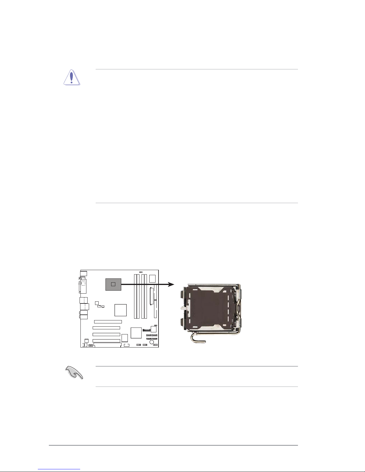
The CPU fits in only one correct orientation. DO NOT force the CPU into
the socket to prevent bending the connectors on the socket and
damaging the CPU!
6. Close the load plate (A), then
push the load lever (B) until
it snaps into the retention
tab.
A
B

ASUS P5LP-LE (Lithium-UL8E)ASUS P5LP-LE (Lithium-UL8E)
ASUS P5LP-LE (Lithium-UL8E) 55
55
5
3. System memory
The motherboard comes with four Double Data Rate 2 (DDR2) Dual Inline
Memory Module (DIMM) sockets.
A DDR2 module has the same physical dimensions as a DDR DIMM but has a
240-pin footprint compared to the 184-pin DDR DIMM. DDR2 DIMMs are
notched differently to prevent installation on a DDR DIMM socket.
The following figure illustrates the location of the DDR2 DIMM sockets.
3.13.1
3.13.1
3.1 Memory configurationsMemory configurations
Memory configurationsMemory configurations
Memory configurations
You can install 256 MB, 512 MB, and 1 GB DDR2 SDRAM DIMMs into the
DIMM sockets using the memory configurations in this section.
• Installing DDR2 DIMMs other than the recommended configurations
may cause memory sizing error or system boot failure. Use any of
the recommended configurations on the next page.
• Install only identicalidentical
identicalidentical
identical (the same type and size) DDR2 DIMM pairs
using the recommended configurations.
• Make sure that the memory frequency matches the CPU FSB (Front
Side Bus). Refer to the Memory frequency/CPU FSB synchronization
table on the next page.
• This motherboard does not support double-sided 16-bit DDR DIMMs.
• Do not create a three-DIMM configuration in dual-channel mode. The
third DIMM is ignored in the dual-channel operation.
P5LP-LE
P5LP-LE 240-pin DDR2 DIMM sockets
DIMM_A1
DIMM_A2
DIMM_B1
DIMM_B2

66
66
6ASUS P5LP-LE (Lithium-UL8E)ASUS P5LP-LE (Lithium-UL8E)
ASUS P5LP-LE (Lithium-UL8E)ASUS P5LP-LE (Lithium-UL8E)
ASUS P5LP-LE (Lithium-UL8E)
Recommended memory configurationsRecommended memory configurations
Recommended memory configurations
* Use only identical DDR2 DIMM pairs.* Use only identical DDR2 DIMM pairs.
* Use only identical DDR2 DIMM pairs.
SocketsSockets
SocketsSockets
Sockets
ModeMode
ModeMode
Mode DIMM1DIMM1
DIMM1DIMM1
DIMM1 DIMM2DIMM2
DIMM2DIMM2
DIMM2 DIMM3DIMM3
DIMM3DIMM3
DIMM3 DIMM4DIMM4
DIMM4DIMM4
DIMM4
Single-channel (1) Installed — — —
(2) — Installed — —
(3) — — Installed —
(4) — — — Installed
Dual-channel* (1) Installed — Installed —
(2) — Installed — Installed
(3) Installed Installed Installed Installed
Memory frequency/CPU FSB synchronizationMemory frequency/CPU FSB synchronization
Memory frequency/CPU FSB synchronization
CPU FSBCPU FSB
CPU FSBCPU FSB
CPU FSB DDR DIMM TypeDDR DIMM Type
DDR DIMM TypeDDR DIMM Type
DDR DIMM Type Memory FrequencyMemory Frequency
Memory FrequencyMemory Frequency
Memory Frequency
1066 MHz PC2-5300/PC2-4200 667/533 MHz
800 MHz PC2-5300/PC2-4200/PC2-3200 667/533/400 MHz
533 MHz PC2-5300/PC2-4200/PC2-3200 667/533/400 MHz

ASUS P5LP-LE (Lithium-UL8E)ASUS P5LP-LE (Lithium-UL8E)
ASUS P5LP-LE (Lithium-UL8E) 77
77
7
3.23.2
3.23.2
3.2 Installing a DDR2 DIMMInstalling a DDR2 DIMM
Installing a DDR2 DIMMInstalling a DDR2 DIMM
Installing a DDR2 DIMM
Unplug the power supply before adding or removing DIMMs or other
system components. Failure to do so can cause severe damage to both
the motherboard and the components.
To install a DIMM:
1. Unlock a DIMM socket by
pressing the retaining clips
outward.
2. Align a DIMM on the socket
such that the notch on the
DIMM matches the break on
the socket.
3. Firmly insert the DIMM into the
socket until the retaining clips
snap back in place and the
DIMM is properly seated.
3.33.3
3.33.3
3.3 Removing a DDR2 DIMMRemoving a DDR2 DIMM
Removing a DDR2 DIMMRemoving a DDR2 DIMM
Removing a DDR2 DIMM
To remove a DIMM:
1. Simultaneously press the retaining
clips outward to unlock the DIMM.
2. Remove the DIMM from the socket.
• A DDR2 DIMM is keyed with a notch so that it fits in only one
direction. Do not force a DIMM into a socket to avoid damaging the
DIMM.
• The DDR2 DIMM sockets do not support DDR DIMMs. Do not install
DDR DIMMs to the DDR2 DIMM sockets.
Unlocked retaining clipUnlocked retaining clip
Unlocked retaining clip
DDR2 DIMM notchDDR2 DIMM notch
DDR2 DIMM notch
Support the DIMM lightly
with your fingers when
pressing the retaining
clips. The DIMM might get
damaged when it flips out
with extra force.
DDR2 DIMM notchDDR2 DIMM notch
DDR2 DIMM notch
1
2
3
1
2
1

88
88
8ASUS P5LP-LE (Lithium-UL8E)ASUS P5LP-LE (Lithium-UL8E)
ASUS P5LP-LE (Lithium-UL8E)ASUS P5LP-LE (Lithium-UL8E)
ASUS P5LP-LE (Lithium-UL8E)
4.14.1
4.14.1
4.1 Installing an expansion cardInstalling an expansion card
Installing an expansion cardInstalling an expansion card
Installing an expansion card
To install an expansion card:
1. Before installing the expansion card, read the documentation that
came with it and make the necessary hardware settings for the card.
2. Remove the system unit cover (if your motherboard is already
installed in a chassis).
3. Remove the bracket opposite the slot that you intend to use. Keep
the screw for later use.
4. Align the card connector with the slot and press firmly until the card is
completely seated on the slot.
5. Secure the card to the chassis with the screw you removed earlier.
6. Replace the system cover.
4.24.2
4.24.2
4.2 Configuring an expansion cardConfiguring an expansion card
Configuring an expansion cardConfiguring an expansion card
Configuring an expansion card
After installing the expansion card, configure it by adjusting the software
settings.
1. Turn on the system and change the necessary BIOS settings, if any.
2. Assign an IRQ to the card. Refer to the tables on the next page.
3. Install the software drivers for the expansion card.
4. Expansion slots
In the future, you may need to install expansion cards. The following
sub-sections describe the slots and the expansion cards that they support.
Make sure to unplug the power cord before adding or removing
expansion cards. Failure to do so may cause you physical injury and
damage motherboard components.
When using PCI cards on shared slots, ensure that the drivers support
“Share IRQ” or that the cards do not need IRQ assignments; otherwise,
conflicts will arise between the two PCI groups, making the system
unstable and the card inoperable. Refer to the table on the next page for
details.

ASUS P5LP-LE (Lithium-UL8E)ASUS P5LP-LE (Lithium-UL8E)
ASUS P5LP-LE (Lithium-UL8E) 99
99
9
Standard interrupt assignmentsStandard interrupt assignments
Standard interrupt assignments
IRQIRQ
IRQIRQ
IRQ Standard FunctionStandard Function
Standard FunctionStandard Function
Standard Function
0 System Timer
1 Standard 101/102-key or Microsoft
®
Natural PS/2 Keyboard
2 Programmable Interrupt Controller
3 Intel
®
USB Enhanced Host Controller
3 Intel
®
USB Universal Host Controller
4 Intel
®
USB Universal Host Controller
6 Standard Floppy Disk Controller
7 ECP Printer Port
8 System CMOS/Real Time Clock
9 SCI IRQ used by ACPI Bus
10 Intel
®
PCI Express Root Port
10 Intel
®
VGA Controller
10 Intel
®
ICH7 High Definition Audio Controller
10 Intel
®
USB Universal Host Controller
11 VIA OHCI Compliant IEEE 1394 Host Controller
11 Intel
®
ICH7 Integrated LAN Controller
12 Microsoft
®
Port Mouse
13 Numeric Data Processor
14 Intel
®
USB Universal Host Controller
14 Intel
®
Ultra ATA Storage Controllers
14 Intel
®
SMBus Controller
IRQ assignments for this motherboardIRQ assignments for this motherboard
IRQ assignments for this motherboard
AB CDE F
PCI slot 1 — — — shared — —
PCI slot 2 shared — — — — —
PCI slot 3 — used — — — —
PCI slot 4 — — — shared — —
PCI slot 5 shared — — — — —
Onboard LAN — — — — — used
Onboard 1394 controller — — — — used —

1010
1010
10 ASUS P5LP-LE (Lithium-UL8E)ASUS P5LP-LE (Lithium-UL8E)
ASUS P5LP-LE (Lithium-UL8E)ASUS P5LP-LE (Lithium-UL8E)
ASUS P5LP-LE (Lithium-UL8E)
PCI slotsPCI slots
PCI slotsPCI slots
PCI slots
There are three 32-bit PCI slots on
this motherboard. The slots
support PCI cards such as a LAN
card, SCSI card, USB card, and
other cards that comply with PCI
specifications.
PCI Express slotPCI Express slot
PCI Express slot
This motherboard has one PCI
Express slot, which supports a
164-pin x16 interface graphics
card.
PCI Expansion slotPCI Expansion slot
PCI Expansion slot
This slot supports a daughterboard
to accommodate two additional PCI
slots.

ASUS P5LP-LE (Lithium-UL8E)ASUS P5LP-LE (Lithium-UL8E)
ASUS P5LP-LE (Lithium-UL8E) 1111
1111
11
5. Jumpers
Clear RTC RAM (3-pin CLRTC)Clear RTC RAM (3-pin CLRTC)
Clear RTC RAM (3-pin CLRTC)
This jumper allows you to clear the Real Time Clock (RTC) RAM in
CMOS. You can clear the CMOS memory of date, time, and system
setup parameters by erasing the CMOS RTC RAM data. The onboard
button cell battery powers the RAM data in CMOS, which include
system setup information such as system passwords.
To erase the RTC RAM:
1. Turn OFF the computer and unplug the power cord.
2. Move the jumper cap from pins 1-2 (Normal) to pins 2-3 (Clear
CMOS). Keep the cap on pins 2-3 for about 5~10 seconds, then
move the cap back to pins 1-2.
3. Plug the power cord and turn ON the computer.
4. Hold down the <Del> key during the boot process and enter BIOS
setup to re-enter data.
Except when clearing the RTC RAM, never remove the cap from the
default position. Removing the cap will cause system boot failure!
Clear password (3-pin CLPWD)Clear password (3-pin CLPWD)
Clear password (3-pin CLPWD)
This jumper allows you to clear the password if you forgot your
password.
P5LP-LE
P5LP-LE Clear password setting
CLPWD
Normal
Clear Password
(Default)
12 23
12 23
P5LP-LE
P5LP-LE Clear RTC RAM
CLRTC
Normal Clear CMOS
(Default)

1212
1212
12 ASUS P5LP-LE (Lithium-UL8E)ASUS P5LP-LE (Lithium-UL8E)
ASUS P5LP-LE (Lithium-UL8E)ASUS P5LP-LE (Lithium-UL8E)
ASUS P5LP-LE (Lithium-UL8E)
1.1.
1.1.
1. PS/2 mouse port (green).PS/2 mouse port (green).
PS/2 mouse port (green).PS/2 mouse port (green).
PS/2 mouse port (green). This port is for a PS/2 mouse.
2.2.
2.2.
2. Parallel port.Parallel port.
Parallel port.Parallel port.
Parallel port. This 25-pin port connects a parallel printer, a scanner,
or other devices.
3.3.
3.3.
3. IEEE 1394a port.IEEE 1394a port.
IEEE 1394a port.IEEE 1394a port.
IEEE 1394a port. This 6-pin IEEE 1394a port provides high-speed
connectivity for audio/video devices, storage peripherals, PCs, or
portable devices.
4.4.
4.4.
4. LAN (RJ-45) port.LAN (RJ-45) port.
LAN (RJ-45) port.LAN (RJ-45) port.
LAN (RJ-45) port. This port allows connection to a Local Area
Network (LAN) through a network hub.
5.5.
5.5.
5. Side Speaker Out port (gray).Side Speaker Out port (gray).
Side Speaker Out port (gray).Side Speaker Out port (gray).
Side Speaker Out port (gray). This port connects to the side
speakers in an 8-channel audio configuration.
6.6.
6.6.
6. Rear Speaker Out port (black).Rear Speaker Out port (black).
Rear Speaker Out port (black).Rear Speaker Out port (black).
Rear Speaker Out port (black). This port connects to the rear
speakers on a 4-channel, 6-channel, or 8-channel audio configuration.
7.7.
7.7.
7. Center/Subwoofer port (yellow orange).Center/Subwoofer port (yellow orange).
Center/Subwoofer port (yellow orange).Center/Subwoofer port (yellow orange).
Center/Subwoofer port (yellow orange). This port connects
the center/subwoofer speakers.
8.8.
8.8.
8. Line In port (light blue).Line In port (light blue).
Line In port (light blue).Line In port (light blue).
Line In port (light blue). This port connects a tape, CD, DVD
player or other audio sources.
9.9.
9.9.
9. Line Out port (lime).
Line Out port (lime).
Line Out port (lime).Line Out port (lime).
Line Out port (lime). This port connects a headphone or a
speaker. In 4-channel, 6-channel, and 8-channel mode, the function of
this port becomes Front Speaker Out.
10.10.
10.10.
10. Microphone port (pink).Microphone port (pink).
Microphone port (pink).Microphone port (pink).
Microphone port (pink). This port connects a microphone.
6. Connectors
6.16.1
6.16.1
6.1 Rear panel connectorsRear panel connectors
Rear panel connectorsRear panel connectors
Rear panel connectors
1
15
8
9
10
11
2 43
12
5
6
7
1314
Refer to the audio configuration table on the next page for the function
of the audio ports in 2, 4, 6, or 8-channel configuration.

ASUS P5LP-LE (Lithium-UL8E)ASUS P5LP-LE (Lithium-UL8E)
ASUS P5LP-LE (Lithium-UL8E) 1313
1313
13
Audio 2, 4, 6, or 8-channel configurationAudio 2, 4, 6, or 8-channel configuration
Audio 2, 4, 6, or 8-channel configuration
Headset/Headset/
Headset/Headset/
Headset/
2-channel2-channel
2-channel2-channel
2-channel 4-channel4-channel
4-channel4-channel
4-channel 6-channel6-channel
6-channel6-channel
6-channel 8-channel8-channel
8-channel8-channel
8-channel
Light Blue Line In Line In Line In Line In
Lime Line Out Front Speaker Out Front Speaker Out Front Speaker Out
Pink Mic In Mic In Mic In Mic In
Yellow Orange - - Center/Subwoofer Center/Subwoofer
Black - Rear Speaker Out Rear Speaker Out Rear Speaker Out
Gray - - - Side Speaker Out
11.11.
11.11.
11. USB 2.0 ports 3 and 4.USB 2.0 ports 3 and 4.
USB 2.0 ports 3 and 4.USB 2.0 ports 3 and 4.
USB 2.0 ports 3 and 4. These two 4-pin Universal Serial Bus
(USB) ports are available for connecting USB 2.0 devices.
12.12.
12.12.
12. USB 2.0 ports 1 and 2.USB 2.0 ports 1 and 2.
USB 2.0 ports 1 and 2.USB 2.0 ports 1 and 2.
USB 2.0 ports 1 and 2. These two 4-pin Universal Serial Bus
(USB) ports are available for connecting USB 2.0 devices.
13.13.
13.13.
13. Coaxial S/PDIF Out port.Coaxial S/PDIF Out port.
Coaxial S/PDIF Out port.Coaxial S/PDIF Out port.
Coaxial S/PDIF Out port. This port connects an external audio
output device via a coaxial S/PDIF cable.
14.14.
14.14.
14. Coaxial S/PDIF In port.Coaxial S/PDIF In port.
Coaxial S/PDIF In port.Coaxial S/PDIF In port.
Coaxial S/PDIF In port. This port connects an external audio input
device via a coaxial S/PDIF cable.
15.15.
15.15.
15. PS/2 keyboard port (purple).PS/2 keyboard port (purple).
PS/2 keyboard port (purple).PS/2 keyboard port (purple).
PS/2 keyboard port (purple). This port is for a PS/2 keyboard.

1414
1414
14 ASUS P5LP-LE (Lithium-UL8E)ASUS P5LP-LE (Lithium-UL8E)
ASUS P5LP-LE (Lithium-UL8E)ASUS P5LP-LE (Lithium-UL8E)
ASUS P5LP-LE (Lithium-UL8E)
6.26.2
6.26.2
6.2 Internal connectorsInternal connectors
Internal connectorsInternal connectors
Internal connectors
This section describes and illustrates the internal connectors on the
motherboard.
1.1.
1.1.
1. Floppy disk drive connector (34-1 pin FLOPPY)Floppy disk drive connector (34-1 pin FLOPPY)
Floppy disk drive connector (34-1 pin FLOPPY)Floppy disk drive connector (34-1 pin FLOPPY)
Floppy disk drive connector (34-1 pin FLOPPY)
This connector is for the provided floppy disk drive (FDD) signal cable.
Insert one end of the cable to this connector, then connect the other
end to the signal connector at the back of the floppy disk drive.
Pin 5 on the connector is removed to prevent incorrect cable connection
when using an FDD cable with a covered Pin 5.
P5LP-LE
NOTE: Orient the red markings on
the floppy ribbon cable to PIN 1.
P5LP-LE Floppy disk drive connector
FLOPPY
PIN 1

ASUS P5LP-LE (Lithium-UL8E)ASUS P5LP-LE (Lithium-UL8E)
ASUS P5LP-LE (Lithium-UL8E) 1515
1515
15
2.2.
2.2.
2. IDE connector (40-1 pin IDE)IDE connector (40-1 pin IDE)
IDE connector (40-1 pin IDE)IDE connector (40-1 pin IDE)
IDE connector (40-1 pin IDE)
This connector is for an Ultra DMA 100/66 signal cable. The Ultra DMA
100/66 signal cable has three connectors: a blue connector for the
primary IDE connector on the motherboard, a black connector for an
Ultra DMA 100/66 IDE slave device (optical drive/hard disk drive), and
a gray connector for an Ultra DMA 100/66 IDE master device (hard disk
drive). If you install two hard disk drives, you must configure the
second drive as a slave device by setting its jumper accordingly. Refer
to the hard disk documentation for the jumper settings.
• Pin 20 on the IDE connector is removed to match the covered hole
on the Ultra DMA cable connector. This prevents incorrect insertion
when you connect the IDE cable.
• Use the 80-conductor IDE cable for Ultra DMA 100/66 IDE devices.
P5LP-LE
P5LP-LE IDE connector
NOTE: Orient the red markings
(usually zigzag) on the IDE
ribbon cable to PIN 1.
IDE
PIN 1

1616
1616
16 ASUS P5LP-LE (Lithium-UL8E)ASUS P5LP-LE (Lithium-UL8E)
ASUS P5LP-LE (Lithium-UL8E)ASUS P5LP-LE (Lithium-UL8E)
ASUS P5LP-LE (Lithium-UL8E)
3.3.
3.3.
3. ATX power connectors (24-pin ATXPWR, 4-pin ATX12V)ATX power connectors (24-pin ATXPWR, 4-pin ATX12V)
ATX power connectors (24-pin ATXPWR, 4-pin ATX12V)ATX power connectors (24-pin ATXPWR, 4-pin ATX12V)
ATX power connectors (24-pin ATXPWR, 4-pin ATX12V)
These connectors are for ATX power supply plugs. The power supply
plugs are designed to fit these connectors in only one orientation.
Find the proper orientation and push down firmly until the connectors
completely fit.
•
Do not forget to connect the 4-pin ATX +12 V power plug;
otherwise, the system will not boot up.
•
Make sure that your ATX 12V power supply can provide 8A on the
+12V lead and at least 1A on the +5-volt standby lead (+5VSB).
The minimum recommended wattage is 230W, or 300W for a fully
configured system. The system can become unstable and might
experience difficulty powering up if the power supply is inadequate.
• You must install a PSU with a higher power rating if you intend to
install additional devices.
P5LP-LE
P5LP-LE ATX power connectors
ATXPWR
ATX12V
+12V DCGND
+12V DCGND
+3 Volts
+3 Volts
Ground
+5 Volts
+5 Volts
Ground
Ground
Power OK
+5V Standby
+12 Volts
-5 Volts
+5 Volts
+3 Volts
-12 Volts
Ground
Ground
Ground
PSON#
Ground
+5 Volts
+12 Volts
+3 Volts
+5 Volts
Ground
Other manuals for Leonite P5LP-LE
2
Table of contents
Other Asus Motherboard manuals

Asus
Asus A7N8X Series User manual

Asus
Asus P5GPL Quick start guide

Asus
Asus B250 MINING EXPERT User manual

Asus
Asus ROG STRIX X370-F GAMING User manual

Asus
Asus AAEON PICO-APL3-SEMI User manual

Asus
Asus M5A97 EVO User manual

Asus
Asus P2B-F User manual

Asus
Asus EX-B365M-V5 User manual

Asus
Asus PC-DL Deluxe User manual

Asus
Asus P5LD2-DH User manual

Asus
Asus M2NPV-VM User manual

Asus
Asus P4G8X User manual

Asus
Asus PRIME B350-PLUS User manual

Asus
Asus A7N8X Deluxe 2.0 User manual

Asus
Asus H310M-C/HDMI User manual

Asus
Asus P5KR User manual

Asus
Asus H170I-PLUS D3 User manual

Asus
Asus K8V-VM Ultra User manual

Asus
Asus PRIME Z690-P WIFI D4 User manual

Asus
Asus TPM-SPI-A User manual