Asus M4A785D-M PRO User manual

Motherboard
M4A785D-M PRO
E4711_M4A785D-M PRO.indb 1 7/6/09 9:09:17 AM

ii
Copyright © 2009 ASUSTeK Computer Inc. All Rights Reserved.
No part of this manual, including the products and software described in it, may be reproduced,
transmitted, transcribed, stored in a retrieval system, or translated into any language in any form or by any
means, except documentation kept by the purchaser for backup purposes, without the express written
permission of ASUSTeK Computer Inc. (“ASUS”).
Product warranty or service will not be extended if: (1) the product is repaired, modied or altered, unless
such repair, modication of alteration is authorized in writing by ASUS; or (2) the serial number of the
product is defaced or missing.
ASUS PROVIDES THIS MANUAL “AS IS” WITHOUT WARRANTY OF ANY KIND, EITHER EXPRESS
OR IMPLIED, INCLUDING BUT NOT LIMITED TO THE IMPLIED WARRANTIES OR CONDITIONS OF
MERCHANTABILITY OR FITNESS FOR A PARTICULAR PURPOSE. IN NO EVENT SHALL ASUS, ITS
DIRECTORS, OFFICERS, EMPLOYEES OR AGENTS BE LIABLE FOR ANY INDIRECT, SPECIAL,
INCIDENTAL, OR CONSEQUENTIAL DAMAGES (INCLUDING DAMAGES FOR LOSS OF PROFITS,
LOSS OF BUSINESS, LOSS OF USE OR DATA, INTERRUPTION OF BUSINESS AND THE LIKE),
EVEN IF ASUS HAS BEEN ADVISED OF THE POSSIBILITY OF SUCH DAMAGES ARISING FROM ANY
DEFECT OR ERROR IN THIS MANUAL OR PRODUCT.
SPECIFICATIONS AND INFORMATION CONTAINED IN THIS MANUAL ARE FURNISHED FOR
INFORMATIONAL USE ONLY, AND ARE SUBJECT TO CHANGE AT ANY TIME WITHOUT NOTICE,
AND SHOULD NOT BE CONSTRUED AS A COMMITMENT BY ASUS. ASUS ASSUMES NO
RESPONSIBILITY OR LIABILITY FOR ANY ERRORS OR INACCURACIES THAT MAY APPEAR IN THIS
MANUAL, INCLUDING THE PRODUCTS AND SOFTWARE DESCRIBED IN IT.
Products and corporate names appearing in this manual may or may not be registered trademarks or
copyrights of their respective companies, and are used only for identication or explanation and to the
owners’ benet, without intent to infringe.
E4711
First Edition V1
June 2009
E4711_M4A785D-M PRO.indb 2 7/6/09 9:09:17 AM

iii
Contents
Notices......................................................................................................... vi
Safety information ..................................................................................... vii
About this guide ....................................................................................... viii
M4A785D-M PRO specications summary............................................... ix
Chapter 1: Product introduction
1.1 Welcome! ...................................................................................... 1-1
1.2 Package contents......................................................................... 1-1
1.3 Special features............................................................................ 1-1
1.3.1 Product highlights ........................................................... 1-1
1.3.2 Innovative ASUS features ............................................... 1-3
1.4 Before you proceed ..................................................................... 1-4
1.5 Motherboard overview................................................................. 1-5
1.5.1 Placement direction ........................................................ 1-5
1.5.2 Screw holes .................................................................... 1-5
1.5.3 Motherboard layout ......................................................... 1-6
1.5.4 Layout contents............................................................... 1-6
1.6 Central Processing Unit (CPU) ................................................... 1-7
1.6.1 Installing the CPU ........................................................... 1-7
1.6.2 Installing the heatsink and fan ........................................ 1-9
1.7 System memory ......................................................................... 1-10
1.7.1 Overview ....................................................................... 1-10
1.7.2 Memory congurations...................................................1-11
1.7.3 Installing a DIMM .......................................................... 1-18
1.7.4 Removing a DIMM ........................................................ 1-18
1.8 Expansion slots.......................................................................... 1-19
1.8.1 Installing an expansion card ......................................... 1-19
1.8.2 Conguring an expansion card ..................................... 1-19
1.8.3 PCI slots........................................................................ 1-19
1.8.4 PCI Express x1 slot....................................................... 1-19
1.8.5 PCI Express x16 slot..................................................... 1-19
1.9 Jumpers ...................................................................................... 1-20
1.10 Connectors ................................................................................. 1-21
1.10.1 Rear panel connectors.................................................. 1-21
1.10.2 Internal connectors ....................................................... 1-24
E4711_M4A785D-M PRO.indb 3 7/6/09 9:09:17 AM

iv
Contents
1.11 Software support........................................................................ 1-30
1.11.1 Installing an operating system ...................................... 1-30
1.11.2 Support DVD information .............................................. 1-30
Chapter 2: BIOS information
2.1 Managing and updating your BIOS ............................................ 2-1
2.1.1 ASUS Update utility ........................................................ 2-1
2.1.2 ASUS EZ Flash 2 utility................................................... 2-2
2.1.3 ASUS CrashFree BIOS 3 utility ...................................... 2-3
2.2 BIOS setup program .................................................................... 2-4
2.2.1 BIOS menu screen.......................................................... 2-5
2.2.2 Menu bar......................................................................... 2-5
2.2.3 Navigation keys............................................................... 2-6
2.2.4 Menu items ..................................................................... 2-6
2.2.5 Sub-menu items.............................................................. 2-6
2.2.6 Conguration elds ......................................................... 2-6
2.2.7 General help ................................................................... 2-6
2.2.8 Pop-up window ............................................................... 2-6
2.2.9 Scroll bar......................................................................... 2-6
2.3 Main menu .................................................................................... 2-7
2.3.1 System Time ................................................................... 2-7
2.3.2 System Date ................................................................... 2-7
2.3.3 Primary IDE Master/Slave, SATA 1-3, 5-6, and E-SATA . 2-7
2.3.4 SATA Conguration ......................................................... 2-8
2.3.5 System Information ......................................................... 2-9
2.4 Advanced menu ........................................................................... 2-9
2.4.1 JumperFree Conguration .............................................. 2-9
2.4.2 CPU Conguration ........................................................ 2-12
2.4.3 Chipset.......................................................................... 2-13
2.4.4 Onboard Devices Conguration.................................... 2-14
2.4.5 PCI PnP ........................................................................ 2-15
2.4.6 USB Conguration ........................................................ 2-15
2.5 Power menu................................................................................ 2-16
2.5.1 Suspend Mode ............................................................. 2-16
2.5.2 ACPI
2.0 Support ......................................................... 2-16
2.5.3 ACPI APIC Support ...................................................... 2-16
E4711_M4A785D-M PRO.indb 4 7/6/09 9:09:18 AM

v
Contents
2.5.4 APM Conguration........................................................ 2-16
2.5.5 HW Monitor Conguration............................................. 2-17
2.6 Boot menu .................................................................................. 2-17
2.6.1 Boot Device Priority ...................................................... 2-18
2.6.2 Boot Settings Conguration .......................................... 2-18
2.6.3 Security ......................................................................... 2-18
2.7 Tools menu ................................................................................. 2-20
2.7.1 ASUS EZ Flash 2.......................................................... 2-20
2.7.2 Express Gate ............................................................... 2-20
2.7.3 AI NET 2........................................................................ 2-20
2.8 Exit menu.................................................................................... 2-21
E4711_M4A785D-M PRO.indb 5 7/6/09 9:09:18 AM

vi
Notices
Federal Communications Commission Statement
This device complies with Part 15 of the FCC Rules. Operation is subject to the following two
conditions:
• This device may not cause harmful interference, and
• This device must accept any interference received including interference that may cause
undesired operation.
This equipment has been tested and found to comply with the limits for a Class B digital
device, pursuant to Part 15 of the FCC Rules. These limits are designed to provide
reasonable protection against harmful interference in a residential installation. This
equipment generates, uses and can radiate radio frequency energy and, if not installed
and used in accordance with manufacturer’s instructions, may cause harmful interference
to radio communications. However, there is no guarantee that interference will not occur
in a particular installation. If this equipment does cause harmful interference to radio or
television reception, which can be determined by turning the equipment off and on, the user
is encouraged to try to correct the interference by one or more of the following measures:
•
Reorient or relocate the receiving antenna.
•
Increase the separation between the equipment and receiver.
•
Connect the equipment to an outlet on a circuit different from that to which the receiver is
connected.
•
Consult the dealer or an experienced radio/TV technician for help.
Canadian Department of Communications Statement
This digital apparatus does not exceed the Class B limits for radio noise emissions from
digital apparatus set out in the Radio Interference Regulations of the Canadian Department
of Communications.
This class B digital apparatus complies with Canadian ICES-003.
The use of shielded cables for connection of the monitor to the graphics card is required
to assure compliance with FCC regulations. Changes or modications to this unit not
expressly approved by the party responsible for compliance could void the user’s authority
to operate this equipment.
DO NOT throw the motherboard in municipal waste. This product has been designed to
enable proper reuse of parts and recycling. This symbol of the crossed out wheeled bin
indicates that the product (electrical and electronic equipment) should not be placed in
municipal waste. Check local regulations for disposal of electronic products.
REACH
Complying with the REACH (Registration, Evaluation, Authorisation, and Restriction of
Chemicals) regulatory framework, we published the chemical substances in our products at
ASUS REACH website at http://green.asus.com/english/REACH.htm.
DO NOT throw the mercury-containing button cell battery in municipal waste. This symbol
of the crossed out wheeled bin indicates that the battery should not be placed in municipal
waste.
E4711_M4A785D-M PRO.indb 6 7/6/09 9:09:20 AM

vii
Operation safety
•
Before installing the motherboard and adding devices on it, carefully read all the manuals
that came with the package.
•
Before using the product, ensure that all cables are correctly connected and the power
cables are not damaged. If you detect any damage, contact your dealer immediately.
•
To avoid short circuits, keep paper clips, screws, and staples away from connectors,
slots, sockets and circuitry.
•
Avoid dust, humidity, and temperature extremes. Do not place the product in any area
where it may become wet.
This motherboard should only be used in environments with ambient temperatures between
5℃ (14℉) and 40℃ (104℉).
•
Place the product on a stable surface.
•
If you encounter technical problems with the product, contact a qualied service
technician or your retailer.
Safety information
Electrical safety
• To prevent electric shock hazard, disconnect the power cable from the electric outlet
before relocating the system.
•
When adding or removing devices to or from the system, ensure that the power cables
for the devices are unplugged before the signal cables are connected. If possible,
disconnect all power cables from the existing system before you add a device.
•
Before connecting or removing signal cables from the motherboard, ensure that all
power cables are unplugged.
•
Seek professional assistance before using an adapter or extension cord. These devices
could interrupt the grounding circuit.
• Ensure that your power supply is set to the correct voltage in your area. If you are not
sure about the voltage of the electrical outlet you are using, contact your local power
company.
• If the power supply is broken, do not try to x it by yourself. Contact a qualied service
technician or your retailer.
• The optical S/PDIF is an optional component (may or may not be included in your
motherboard) and is dened as a CLASS 1 LASER PRODUCT.
INVISIBLE LASER RADIATION, AVOID EXPOSURE TO BEAM.
• Never dispose of the battery in re. It could explode and release harmful substances into
the environment.
• Never dispose of the battery with your regular household waste. Take it to a hazardous
material collection point.
• Never replace the battery with an incorrect battery type.
• RISK OF EXPLOSION IF BATTERY IS REPLACED BY AN INCORRECT TYPE.
• DISPOSE OF USED BATTERIES ACCORDING TO THE ABOVE BATTERY-RELATED
INSTRUCTIONS.
E4711_M4A785D-M PRO.indb 7 7/6/09 9:09:21 AM

viii
Where to nd more information
Refer to the following sources for additional information and for product and software
updates.
1. ASUS websites
The ASUS website provides updated information on ASUS hardware and software
products. Refer to the ASUS contact information.
2. Optional documentation
Your product package may include optional documentation, such as warranty yers,
that may have been added by your dealer. These documents are not part of the
standard package.
Conventions used in this guide
To ensure that you perform certain tasks properly, take note of the following symbols used
throughout this manual.
Typography
Bold text Indicates a menu or an item to select.Indicates a menu or an item to select.
Italics
Used to emphasize a word or a phrase.
<Key> Keys enclosed in the less-than and greater-than
sign means that you must press the enclosed key.
Example: <Enter> means that you must press the
Enter or Return key.
<Key1>+<Key2>+<Key3> If you must press two or more keys simultaneously,
the key names are linked with a plus sign (+).
Example: <Ctrl>+<Alt>+<D>
DANGER/WARNING:Information to prevent injury to yourselfInformation to prevent injury to yourself
when trying to complete a task.
CAUTION: Information to prevent damage to the componentsInformation to prevent damage to the components
when trying to complete a task.
NOTE: Tips and additional information to help you complete a task.Tips and additional information to help you complete a task.
IMPORTANT: Instructions that you MUST follow to complete a task.
About this guide
This user guide contains the information you need when installing and conguring the
motherboard.
How this guide is organized
This guide contains the following parts:
• Chapter 1: Product introduction
This chapter describes the features of the motherboard and the new technology it
supports.
• Chapter 2: BIOS information
This chapter tells how to change system settings through the BIOS Setup menus.
Detailed descriptions of the BIOS parameters are also provided.
E4711_M4A785D-M PRO.indb 8 7/6/09 9:09:22 AM

ix
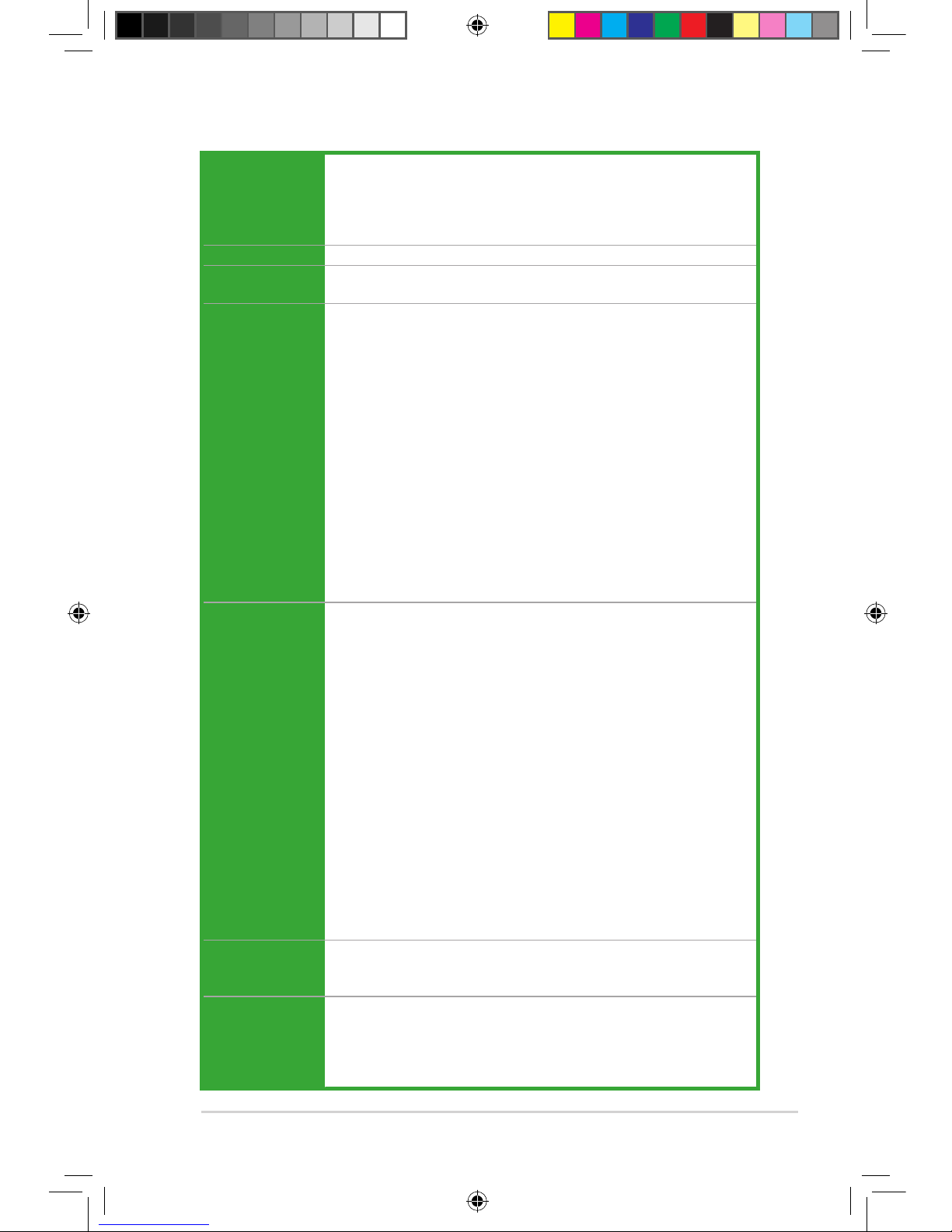
CPU AMD Phenom™II / Athlon™ II / Phenom™/ Athlon ™ /Sempron™
family processors (AM3 / AM2+ / AM2)
Supports 45nm CPU
AMD Cool ‘n’ Quiet™ Technology (depending on CPU type)
Supports CPU up to 125W
Chipset AMD 785G/SB710
System bus Up to 5200 MT/s HyperTransport™ 3.0 interface for AM2+ / AM3 CPU
2000 / 1600 MT/s for AM2 CPU
Memory Dual-channel memory architecture
4 x 240-pin DIMM slots support unbuffered ECC and non-ECC
DDR2 1200 (O.C.)*/1066/800/667MHz memory modules
Supports up to 16GB system memory
* We recommend that you install the DDR2 1200 DIMMs on the
blue slots for better performance.
** DDR2 1200 (O.C.)/1066 is supported by AM3/AM2+ CPU only.
** Due to AM3/AM2+ CPU limitation, only one DDR2 1200 (O.C.)
/1066 is supported per channel.
** Refer to www.asus.com for the latest Memory QVL.
*** Due to the memory address limitation on 32-bit Windows OS,Due to the memory address limitation on 32-bit Windows OS,
when you install 4GB or more memory on the motherboard, the
actual usable memory for the OS can be about 3GB or less. For
effective use of memory, we recommend that you install a 64-bit
Windows OS when having 4GB or more memory installed on the
motherboard.
Graphics Integrated ATI Radeon HD4200 supports:
- maximum shared memory of 512MB
- DVI-D with HDCP compliant with max. resolution 2560x1600
@60Hz dual-link
- HDMI™ Technology with max. resolution up to 1920x1200 (1080P)
@60Hz
- RGB with max. resolution 2560x1440 @75Hz
Hybrid CrossFireX™ support (for Windows Vista only)
Supports Microsoft® DirectX 10.1, OpenGL 2.0, Shader Model 4.1,
Hardware Decode Acceleration for H.264, VC-1, and MPEG-2
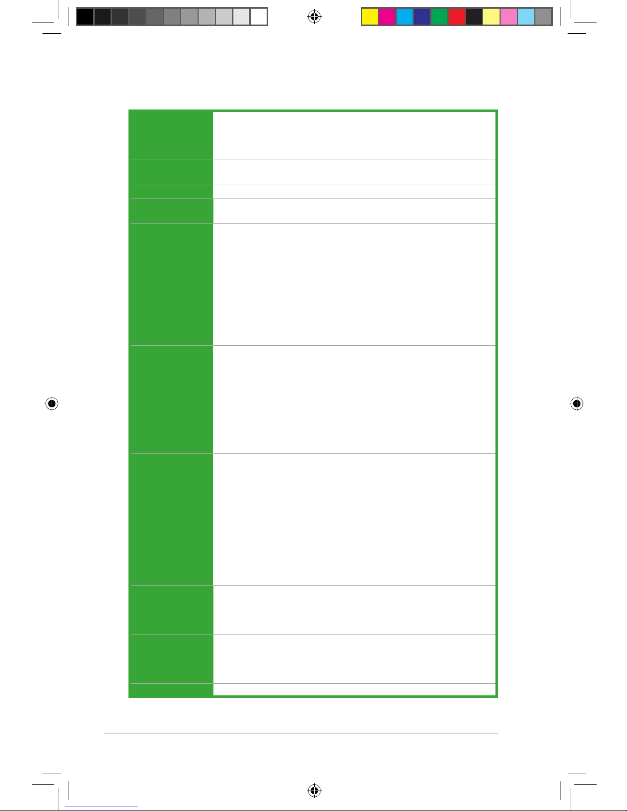
Dual VGA output supports:
- RGB & DVI
- RGB & HDMI
* Refer to www.amd.com for the Hybrid CrossFireX selected GPUs.
** To playback the HD-DVD and Blu-ray Disc, we recommend system
conguration above graphic shared memory 256MB / Dual-Core
CPU minimum 1GB memory of Dual-channel DDR2 667 or single-
channel DDR2 800.
Expansion slots 1 x PCI Express™ 2.0 x16 slot
1 x PCI Express™ x1 slot
2 x PCI 2.2 slots
Storage / RAID 1 x UltraDMA 133/100/66 connector
5 x Serial ATA 3Gb/s connectors support RAID 0, RAID 1, RAID
0+1, and JBOD congurations
1 x External SATA 3Gb/s supports RAID 0, RAID 1, RAID
0+1, and JBOD congurations
M4A785D-M PRO specications summary
(continued on the next page)
E4711_M4A785D-M PRO.indb 9 7/6/09 9:09:22 AM

x
M4A785D-M PRO specications summary
Audio VT1708S High Denition Audio 8-channel CODEC
Supports Jack-detection, Multi-streaming, Single SPDIF Out,
Anti-pop Function and Front Panel Retasking (HD only)
Supports S/PDIF out port at back I/O
USB Supports up to 12 USB 2.0/1.1 ports (6 ports at mid-board,
6 ports at back panel)
LAN Realtek 8112L PCIe Gigabit LAN
BIOS 8Mb Flash ROM, AMI BIOS, PnP, DMI2.0, WfM2.0, ACPI2.0a, SM
BIOS 2.5
ASUS special
features
ASUS 4+1 Phase Power Design
ASUS EPU-4 Engine
ASUS Express Gate
ASUS Turbo Key
ASUS GPU NOS
ASUS CrashFree BIOS 3
ASUS EZ Flash 2
ASUS Q-Fan
ASUS MyLogo 2
ASUS AI NET 2
Back panel I/O
ports
1 x PS/2 Keyboard/Mouse Combo port
1 x Optical S/PDIF Out port
1 x D-Sub port
1 x DVI port
1 x HDMI port
1 x External SATA port
1 x RJ45 port
6 x USB 2.0/1.1 ports
8-channel Audio I/O ports
Internal I/O
connectors
3 x USB 2.0/1.1 connectors support additional 6 USB 2.0/1.1 ports
5 x SATA connectors
1x CPU/Chassis/Power Fan connectors
1 x High Denition front panel audio connector
1 x S/PDIF Out connector
1 x IDE connector
1 x COM connector
1 x Parallel port
1 x system panel connector
24-pin ATX power connector
4-pin ATX 12V power connector
Accessories 2 x Serial ATA cables
1 x UltraDMA 133/100/66 cable
1x IO Shield
User manual
Support DVD Drivers
ASUS Update
ASUS PC Probe II
Anti-Virus software (OEM version)
Form Factor MicroATX form factor: 9.6’’ x 9.6’’ (24.4cm x 24.4cm)
*Specications are subject to change without notice.
E4711_M4A785D-M PRO.indb 10 7/6/09 9:09:23 AM

ASUS M4A785D-M PRO 1-1
1.1 Welcome!
Thank you for buying an ASUS®M4A785D-M PRO motherboard!
The motherboard delivers a host of new features and latest technologies, making it another
standout in the long line of ASUS quality motherboards!
Before you start installing the motherboard, and hardware devices on it, check the items in
your package with the list below.
If any of the above items is damaged or missing, contact your retailer.
1.2 Package contents
Check your motherboard package for the following items.
Motherboard ASUS M4A785D-M PRO motherboard
Cables 2 x Serial ATA cables
1 x Ultra DMA 133/100/66 cable
Accessories 1 x I/O shield
Application DVD ASUS motherboard support DVD
Documentation User guide
Chapter 1
Product introduction
AMD®Phenom™ X4 / Phenom™ X3 / Athlon™ X2 / Athlon™ /
Sempron™ processors (socket AM2+/AM2)
This motherboard supports AMD® Socket AM2+ multi-core processors.
It features dual-channel DDR2 1066 memory support, data transfer rate
up to 5200MT/s via HyperTransport™ 3.0 based system bus, and AMD®
Cool ‘n’ Quiet™ Technology.
AMD®Phenom™ II / Athlon™II / Sempron™ 100 Series
processors
This motherboard supports AMD®AM3 multi-core processors with unique
L3 cache and delivers better overclocking capabilities with less power
consumption. It features dual-channel DDR2 1066 memory support and
accelerates data transfer rate up to 5200MT/s via HyperTransport™ 3.0
based system bus. This motherboard also supports AMD®CPUs in the
new 45nm manufacturing process.
1.3 Special features
1.3.1 Product highlights
E4711_M4A785D-M PRO.indb 1 7/6/09 9:09:26 AM

1-2 Chapter 1: Product introduction
AMD 785G/SB710 chipset is designed to support up to 5200MT/s
HyperTransport™ 3.0 (HT3.0) interface speed and PCI Express™ 2.0 x
16 graphics. It is optimized with AMD’s latest AM3 and multi-core CPUs to
provide excellent system performance and overclocking capabilities.
HyperTransport™ 3.0 support
HyperTransport™ 3.0 technology provides 2.6 times more bandwidth than
HT1.0 that radically improves system efciency for a smoother, faster
computing environment.
AMD®Hybrid CrossFireX Technology
Hybrid CrossFireX Technology is a unique multi-GPU technology
conbining the onboard GPU and he discrete graphics card together to
enhance 3D graphics performance.
• Hybrid CrossFireX is supported by Windows Vista OS only.
• Visit www.amd.com for the Hybird CrossFireX selected GPUs.
AMD Cool ‘n’ Quiet Technology
The motherboard supports the AMD Cool ‘n’ Quiet Technology, which
monitors system operation and automatically adjusts CPU voltage and
frequency for a cool and quiet operating environment.
DDR2 1200 O.C.
This motherboard supports DDR2 1200 (O.C.) that provides faster
data transfer rate and more bandwidth to increase memory computing
efciency, enhancing system performance in 3D graphics and other
memory demanding applications.
Gigabit LAN solution
The onboard LAN controller is a highly integrated Gb LAN controller. It is
enhanced with an ACPI management function to provide efcient power
management for advanced operating systems.
HDMI/DVI/RGB support
This motherboard supports multiple digital and analog display output
interfaces: HDMI, DVI, and D-Sub. With such diversity of display outputs,
you are able to choose and upgrade display devices freely.
HDMI support
HDMI (High-Denition Multimedia Interface) is the rst and only industry-
supported, uncompressed, all digital and video interface via a single cable
and is HDCP compliant allowing playback of HD DVD, Blu-ray disc, and
other protected content. The interface of this motherboard supports dual
VGA output for both HDMI/DVI and RGB.
Serial ATA 3Gb/s technology
The motherboard supports hard drives based on the SATA 3Gb/s storage
specication, delivering enhanced scalability and doubling the bus
bandwidth for high-speed data saving and retrieval.
E4711_M4A785D-M PRO.indb 2 7/6/09 9:09:30 AM

ASUS M4A785D-M PRO 1-3
1.3.2 Innovative ASUS features
ASUS Express Gate
Express Gate is a unique OS built into the motherboard. Five seconds
after bootup, you can instantly surf the Internet without entering the
Windows®OS.
• ASUS Express Gate supports le uploading from SATA HDDs, ODDs, and USB
drives. It supports le downloading to USB devices only.
• The actrual boot time is subject to hardware conguration and product models.
• Express Gate complies with the OpenGL standard. Refer to http://support.asus.com
for Express Gate source codes.
ASUS EPU
The ASUS EPU (Energy Processing Unit) provides total system
power management by detecting current PC loadings and intelligently
moderating power usage for critical PC components in real-time-helping
save power and money!
Turbo Key
ASUS Turbo Key allows you to turn the PC power button into
an overclocking button. After the easy setup, Turbo Key boosts
performances without interrupting ongoing work or games, simply through
pressing the button.
ASUS GPU NOS support
ASUS GPU NOS technology intelligently detects graphics loading
and automatically boosts performance for the most demanding tasks.
It provides you with a faster reaction time for an excellent graphics
performance.
SATA-On-The-Go
The external SATA port located at the back I/O provides smart setup and
hot-plug functions. Easily backup photos, videos and other entertainment
contents to external devices.
High Denition Audio
The onboard 8-channel VT1708S High Denition Audio CODEC enables
high-quality audio that automatically detects peripherals plugged into the
audio I/O jacks. VT1708S also supports the Windows®Vista Premium OS.
S/PDIF digital sound ready
This motherboard provides convenient connectivity to external home
theater audio systems via the optical S/PDIF (SONY-PHILIPS Digital
Interface) Out jack. It allows digital audio transferring without converting it
to analog format, and therefore well preserves singnal quality.
E4711_M4A785D-M PRO.indb 3 7/6/09 9:09:33 AM

1-4 Chapter 1: Product introduction
1.4 Before you proceed
Take note of the following precautions before you install motherboard components or change
any motherboard settings.
• Unplug the power cord from the wall socket before touching any component.
• Use a grounded wrist strap or touch a safely grounded object or a metal object, such
as the power supply case, before handling components to avoid damaging them due to
static electricity
• Hold components by the edges to avoid touching the ICs on them.
• Whenever you uninstall any component, place it on a grounded antistatic pad or in the
bag that came with the component.
• Before you install or remove any component, ensure that the ATX power supply is
switched off or the power cord is detached from the power supply. Failure to do so may
cause severe damage to the motherboard, peripherals, or components.
AI NET2
AI NET2 remotely detects cable connection the second you turn on the
system, and any faulty connections are reported back up to 100 meters at
1 meter accuracy.
ASUS MyLogo2™
Turn your favorite photos into 256-color boot logos to personalize your
system.
ASUS CrashFree BIOS 3
ASUS CrashFree BIOS 3 is an auto-recovery tool that allows you to
restore a corrupted BIOS le using the bundled support DVD or USB
ash disk that contains the BIOS le.
ASUS EZ Flash 2
ASUS EZ Flash 2 is a utility that allows you to update the BIOS without
using a bootable oppy disk or an OS-based utility.
Green ASUS
This motherboard and its packaging comply with the European Union’s
Restriction on the use of Hazardous Substances (RoHS). This is in line
with the ASUS vision of creating environment-friendly and recyclable
products/packaging to safeguard consumers’ health while minimizing the
impact on the environment.
CPU Parameter Recall (C.P.R)
The BIOS C.P.R. feature automatically restores the CPU default settings
when the system hangs due to overclocking failure. C.P.R. eliminates the
need to open the system chassis and clear the RTC data. Simply shut
down and reboot the system, and the BIOS automatically restores the
CPU parameters to their default settings.
E4711_M4A785D-M PRO.indb 4 7/6/09 9:09:35 AM

ASUS M4A785D-M PRO 1-5
Onboard LED
The motherboard comes with a standby power LED that lights up to indicate that the system
is ON, in sleep mode, or in soft-off mode. This is a reminder that you should shut down
the system and unplug the power cable before removing or plugging in any motherboard
component. The illustration below shows the location of the onboard LED.
Do not overtighten the screws! Doing so can damage the motherboard.
1.5.1 Placement direction
When installing the motherboard, ensure that you place it into the chassis in the correct
orientation. The edge with external ports goes to the rear part of the chassis as indicated in
the image below.
Place this side towards
the rear of the chassis.
1.5.2 Screw holes
Place eight screws into the holes indicated by circles to secure the motherboard to the
chassis.
1.5 Motherboard overview
E4711_M4A785D-M PRO.indb 5 7/6/09 9:09:36 AM

1-6 Chapter 1: Product introduction
1.5.3 Motherboard layout
Connectors/Jumpers/Slots Page Connectors/Jumpers/Slots Page
1. CPU, chassis, and power fan connectors (4-pin
CPU_FAN, 3-pin CHA_FAN, 3-pin PWR_FAN)
1-29 8. Onboard LED 1-5
2. ATX power connectors (24-pin EATXPWR, 4-pin
ATX12V)
1-24 9. Clear RTC RAM (CLRTC) 1-20
3. AMD CPU socket 1-7 10. System panel connector (20-8 pin PANEL) 1-27
4. DDR2 DIMM sockets 1-10 11. Serial ATA connectors (7-pin SATA1, SATA2,
SATA3, SATA5, SATA6)
1-26
5. Serial port connectors (10-1 pin COM1) 1-29 12. USB connectors (10-1 pin USB78, USB910,
USB1112)
1-28
6. LPT connector (26-1 pin LPT) 1-26 13. Digital audio connector (4-1 pin SPDIF_OUT) 1-25
7. IDE connector (40-1 pin PRI_IDE) 1-25 14. Front panel audio connector (10-1 pin AAFP) 1-28
1.5.4 Layout contents
E4711_M4A785D-M PRO.indb 6 7/6/09 9:09:37 AM

ASUS M4A785D-M PRO 1-7
1.6 Central Processing Unit (CPU)
The motherboard comes with an AM2+ / AM2 socket designed for Phenom™ II /
Athlon™ II / Phenom™ / Athlon™/ Sempron™ family processors (AM3 / AM2+ / AM2).
The AM3/AM2/AM2+ socket has a different pinout from the 940-pin socket designed for the
AMD Opteron™ processor. Use a CPU that is designed for the AM3/AM2/AM2+ socket.
1.6.1 Installing the CPU
To install a CPU:
1. Locate the CPU socket on the motherboard.
Make sure that the socket lever is lifted up to
a 90º angle; otherwise, the CPU will not t in
completely.
2. Unlock the socket by pressing the lever
sideways, then lift it up to a 90º angle.
Socket lever
3. Position the CPU above the socket such that
the CPU corner with the gold triangle matches
the socket corner with a small triangle.
4. Carefully insert the CPU into the socket until it
ts in place.
The CPU ts only in one correct
orientation. DO NOT force the
CPU into the socket to prevent
bending the pins and damaging
the CPU.
Gold triangle
Small triangle
E4711_M4A785D-M PRO.indb 7 7/6/09 9:09:42 AM

1-8 Chapter 1: Product introduction
7. Connect the CPU fan cable to the CPU_FAN connector on the motherboard.
Do not forget to connect the CPU fan connector! Hardware monitoring errors can occur if
you fail to plug this connector.
5. When the CPU is in place, push down the
socket lever to secure the CPU. The lever
clicks on the side tab to indicate that it is
locked.
6. Install a CPU heatsink and fan following
the instructions that came with the heatsink
package.
E4711_M4A785D-M PRO.indb 8 7/6/09 9:09:44 AM

ASUS M4A785D-M PRO 1-9
1.6.2 Installing the heatsink and fan
Ensure that you use only AMD-certied heatsink and fan assembly.
To install the CPU heatsink and fan:
1. Place the heatsink on top of the installed CPU, making sure that the heatsink ts
properly on the retention module base.
• The retention module base is already installed on the motherboard upon purchase.
• You do not have to remove the retention module base when installing the CPU or
installing other motherboard components.
• If you purchased a separate CPU heatsink and fan assembly, ensure that a Thermal
Interface Material is properly applied to the CPU heatsink or CPU before you install the
heatsink and fan assembly.
CPU Fan
CPU Heatsink
Retention bracket
Retention bracket lock
Retention Module Base
Your boxed CPU heatsink and fan assembly should come with installation instructions for
the CPU, heatsink, and the retention mechanism. If the instructions in this section do not
match the CPU documentation, follow the latter.
2. Attach one end of the retention bracket to the retention module base.
1
34
5
2
E4711_M4A785D-M PRO.indb 9 7/6/09 9:09:46 AM

1-10 Chapter 1: Product introduction
1.7 System memory
1.7.1 Overview
The motherboard comes with four Double Data Rate 2 (DDR2) Dual Inline Memory Modules
(DIMM) sockets. A DDR2 module has the same physical dimensions as a DDR DIMM but
has a 240-pin footprint compared to the 184-pin DDR DIMM. DDR2 DIMMs are notched
differently to prevent installation on a DDR DIMM socket. The gure illustrates the location of
the DDR2 DIMM sockets:
Channel Sockets
Channel A DIMM_A1 and DIMM_A2
Channel B DIMM_B1 and DIMM_B2
3. Align the other end of the retention bracket to the retention module base. A clicking
sound denotes that the retention bracket is in place.
Ensure that the fan and heatsink assembly perfectly ts the retention mechanism module
base, otherwise you cannot snap the retention bracket in place.
4. Push down the retention bracket lock on the retention mechanism to secure the
heatsink and fan to the module base.
5. When the fan and heatsink assembly is in place, connect the CPU fan cable to the
connector on the motherboard labeled CPU_FAN.
Do not forget to connect the CPU fan connector! Hardware monitoring errors can occur if
you fail to plug this connector.
E4711_M4A785D-M PRO.indb 10 7/6/09 9:09:47 AM
Table of contents
Other Asus Motherboard manuals

Asus
Asus PRIME B450M-K User manual

Asus
Asus M2N-VM SE HDMI User manual

Asus
Asus Strix Z270I Gaming User manual

Asus
Asus B85M-G User manual

Asus
Asus ROG STRIX TRX40-E GAMING User manual

Asus
Asus M2N68-CM User manual

Asus
Asus TUF Z270 Mark 1 User manual

Asus
Asus P5LVM1394 User manual

Asus
Asus P4P800 User manual

Asus
Asus CROSSHAIR User manual

Asus
Asus SP98-N User manual

Asus
Asus A7V266-M User manual

Asus
Asus PRIME H470-PLUS User manual

Asus
Asus M5A97 EVO User manual

Asus
Asus TUF GAMING H470-PRO User manual

Asus
Asus TUF Z390M-PRO GAMING WI-FI User manual

Asus
Asus M2N-X PLUS User manual

Asus
Asus J1800I-A User manual

Asus
Asus M3N-HD Technical manual

Asus
Asus M4A78-EM - Motherboard - Micro ATX User manual