ATA HiRO GDO-12 User manual

4008033
Conforms to:
ANSI/CAN/UL325
Tested to comply
with Part 15 of the
FCC Rules
Doc # 160417_02
Part # 87515
Released 22/02/21
$ $
% %
& &
' '
( (
) )
* *
+ +
- -
. .
/ /
0 0
1 1
3 3
5 5
7 7
'5$:1
&+.'
$339'
0)*
4$
81/(6627+(5:,6(63(&,),('
',0(16,216$5(,10,//,0(7(56
685)$&(),1,6+
72/(5$1&(6
/,1($5
$1*8/$5
),1,6+
'(%855$1'
%5($.6+$53
('*(6
1$0(
6,*1$785(
'$7(
0$7(5,$/
'21276&$/('5$:,1*
5(9,6,21
7,7/(
':*12
6&$/(
6+((72)
$
:(,*+7
32:(5'5,9(*'29$<B;;;;;;;;B;;;;;
High Rolling Door Opener
GDO-12HiR
FOR LIGHT-DUTY COMMERCIAL DOOR USE ONLY
Instruction Manual
(Instruction d’Installation)
MODELS: GDO-12V1AM

2HIRO Installation Manual GDO-12V1

HIRO Installation Manual GDO-12V1 3
© Copyright 2019
Contents
1. Safety Information 4
2. Sécurité 5
3. System Specifications 6
4. Kit Contents 7
5. Operator Safety & Security 8
5.1 Your Door CAN NOT be used by the opener when: 8
5.2 Your Door CAN be used when: 8
5.3 To Disengage the Opener: 8
5.4 To Re-Engage the Opener: 8
6. Installation Instructions 9
6.1 Pre-Installation Requirements 10
6.1.1 Door Operation 10
6.1.2 Unsuitable Door Types 10
6.1.3 Position 10
6.1.4 Power Supply 10
6.1.5 Sideroom 10
6.1.6 Forks 10
6.2 Door Preparation 11
6.2.1 Preparation 11
6.2.2 Pinning the Door to the drum: 11
6.2.3 Door prop preparation 11
6.3 Fitting the Opener 12
6.4 Safety Beam Installation 13
6.4.1 Safety Infra-Red Beam Kit (P/N 62047) 13
6.4.2 Assembling the Mounting Bracket 13
6.4.3 Aligning the Transmitter and receiver 13
6.5 Setting Speed and Limits 14
6.5.1 Set the Limit Positions and adjust drive speed: 14
6.5.2 Clearing the Door Limit Positions 14
6.5.3 Re-profiling the Door 14
6.6 Safety Testing & Auto-Close 15
6.6.1 Testing Close Cycle 15
6.6.2 Testing Open Cycle 15
6.6.3 Auto-Close 15
6.7 Coding Transmitters 16
6.7.1 Transmitter Button to Operate Door 17
6.7.2 Installation of the Wall Mounted Transmitter 17
6.7.3 Erasing Programmed Codes 17
6.7.4 Selecting The Function To Be Coded 18
6.7.5 Activate Remote Code Set Mode 18
6.8 Attach Warning Labels 18
7. Operation Instructions 19
7.1 How to Use Your Operator 20
7.1.1 How To Operate the opener: 20
7.1.2 Replacing the Battery: 3V Lithium Battery CR2032. 20
7.2 User Operating Controls 21
7.3 Door Status Indicators 21
7.4 Disposal of Batteries 22
8. User Maintenance Instruction 23
8.1 Door Maintenance 23
8.2 If You Need a Service Call 23
9. Troubleshooting 24
10. Appendix 25
A - Adjustment Mode Parameters 25
B - Setting the PART (Partial) Mode position 25
C - LED Status 26
D - Setting Limits via Transmitter 27
E - Additional Transmitter Functions 28
GDO-12HiR
High Roll Up Garage Door Opener

4HIRO Installation Manual GDO-12V1
1. Safety Information
Please read these important safety rules
These safety alert symbols indicate a personal
safety or property damage instruction exists.
READ THESE INSTRUCTIONS CAREFULLY.
This automatic garage door operator is designed and tested
to offer safe service provided it is installed and operated
in strict accordance with the following safety rules. Failure
to comply with the installation instructions and the safety
warnings may result in death, serious personal injury and/or
property damage.
WARNING! It is vital for the safety of persons
to follow all instructions. Failure to comply with the
installation instructions and the safety warnings may
result in serious personal injury and/or property and
remote control opener damage. Please save these
instructions for future reference.
• This operator should be installed in accordance with relevant US and
Canada Standards.
•To reduce the risk of injury to persons – Use this operator
only with a rolling door. The drive must not be used with a door
incorporating a wicket door, unless the drive cannot be operated with
the wicket door open.
• All warning signs and placards must be installed where visible in the
area of the door.
• This operator is a plug in domestic appliance and is designed for
indoor use only. It must be installed in a dry position that is protected
from the weather.
• Door must have Safety Beams fitted.
• Activate the operator only when the garage door is in full view, free of
obstructions and with the operator properly adjusted.
• The network device allows for operation of the door when not in line-
of-sight of the door and operator. Therefore the door may operate
unexpectedly, therefore do not allow anything to stay in or near the
path of the door.
• Watch the moving door and keep people away until the door is
completely opened or closed.
ELECTROCUTION: To reduce the risk of
electric shock, this equipment has a grounding type
plug that has a third (grounding) pin. This plug will only
fit into a grounding type outlet. If the plug does not fit
into the outlet, contact a qualified electrician to install
the proper outlet. Do not change the plug in any way.
This operator is not equipped for permanent wiring.
Contact a qualified electrician to install a suitable
receptacle if one is not available.
• Installation and wiring must be in compliance with your local building
and electrical codes.
• If the power cord is damaged, it must be replaced by the manufacturer,
its service agent or a similarly qualified person in order to avoid a
hazard.
• Connect the power cord only to properly earthed mains. If an
extension lead must be used, make sure it is a 3-core lead and
approved to 7 amp capacity.
• This unit is not user serviceable. Unplug the power cord before
removing the cover. Ensure that the power cord is attached clear of
all moving parts. Ignoring these instructions can cause electric shock.
CAUTION:
• If your garage has no pedestrian entrance door, an emergency
access device should be installed. This accessory allows manual
operation of the garage door from outside in case of power failure.
• Keep the garage door balanced. Sticking or binding doors must be
repaired. Garage doors, door springs, brackets and their hardware
are under extreme tension and can cause serious personal injury.
Do not attempt any garage door adjustment. Do not use if repair
or adjustment is needed. Call for professional garage door service.
• Position the Garage Door Operator so that the power plug is
accessible when inserted into the power outlet.
• Install the wall transmitter in a location where the garage door is
visible, but out of the reach of children at a height of at least 5 feet
(1.53m).
• To avoid serious personal injury from entanglement, remove all
unnecessary ropes or chains and disable any equipment such as
locks which are not needed for powered operation.
• Do not wear rings, watches or loose clothing while installing or
servicing a garage door operator.
• Ensure ladder is the correct type for the job and is on flat ground.
We recommend the user has 3 points of contact while on ladder.
• Activate the operator only when the garage door is in full view,
free of obstructions and with the operator properly adjusted.
• The operator is not intended for use by young children or infirm
persons without supervision.
• Keep transmitters away from children.
• Do not allow children to play with door controls.

HIRO Installation Manual GDO-12V1 5
© Copyright 2019
Please read these important safety rules
2. Sécurité
Lisez attentivement ces règles de
sécurité.
Ces pictogrammes indiquent une consigne
de sécurité pour les personnes ou les biens.
LISEZ CES INSTRUCTIONS ATTENTIVEMENT.
Cette commande automatique pour porte de garage est
conçue et testée pour fonctionner en toute sécurité. Pour
ce faire, elle doit être installée et utilisée dans le strict
respect des règles de sécurité suivantes. Le non-respect des
instructions d'installation et des avertissements présent un
risque de mort, de blessure grave et/ou de préjudice pour
les biens.
AVERTISSEMENT ! pour la sécurité des
usagers, il est essentiel de suivre toutes les instructions.
Le non- respect des instructions d’installation et
des avertissements de sécurité peut causer de
graves blessures et/ou endommager l’appareil et la
télécommande. Conservez ces instructions en lieu sûr.
• Cet appareil doit être installé conformément aux normes US et
canadiennes en vigueur.
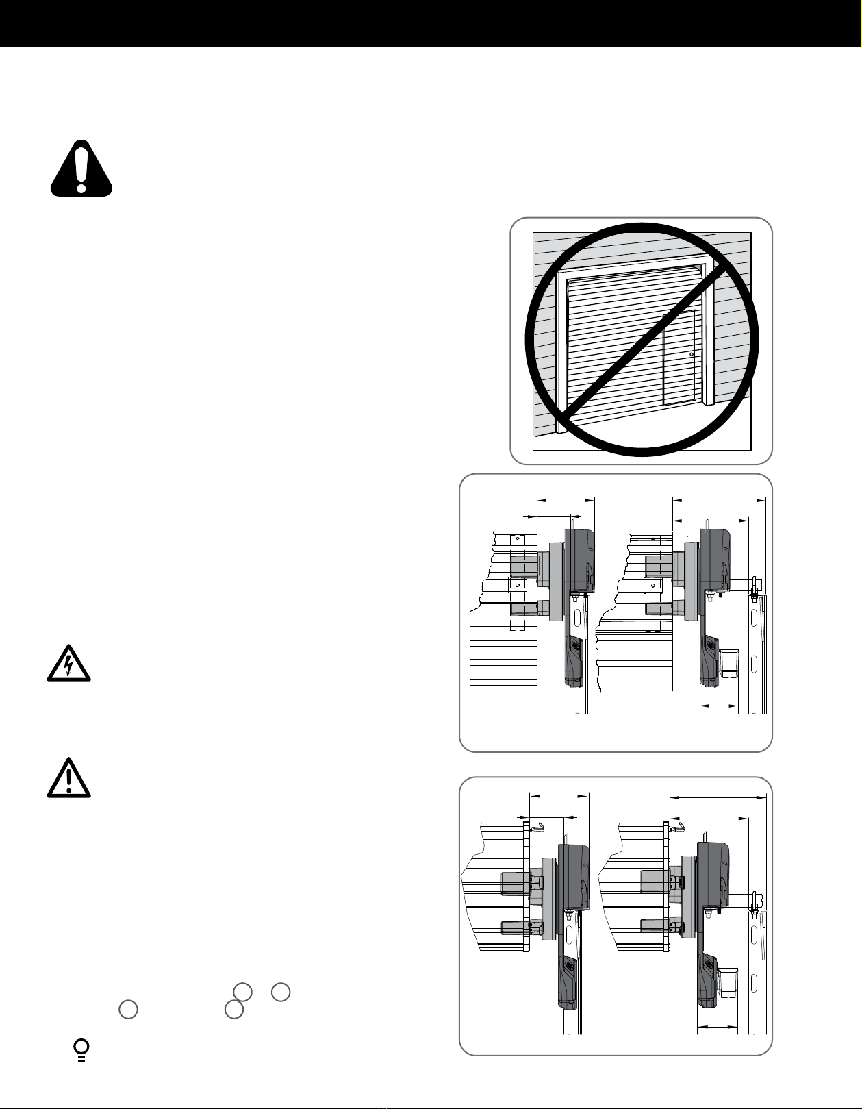
• Pour réduire les risques d’accident, n’utiliser cet appareil qu’avec
une porte de garage enroulable. Ce moteur ne doit pas être utilisé
avec une porte de garage avec portillon, à moins que le moteur ne
puisse fonctionner quand le portillon est ouvert.
• Toutes les étiquettes et les panneaux de mise en grade doivent être
installés à un endroit visible près de la porte.
• Cet appareil est un accessoire domestique conçu pour être utilisé
uniquement à l'intérieur. Il doit être installé au sec et à l'abri des
intempéries.
• La porte doit être équipée de faisceaux de sécurité.
• Activez l'appareil uniquement lorsque la porte du garage est à la vue,
exempte d'obstacles et avec l'appareil bien réglé.
• La télécommande radio permet d’actionner la porte lorsque
l’utilisateur est hors de la ligne de vue de la porte et de l’appareil. En
conséquence, la porte risque de s’ouvrir ou se fermer inopinément et
vous devez éviter de laisser des objets sur sa course ou à proximité.
• Suivez la porte pendant l'ouverture ou la fermeture, et veillez à
ce que personne ne se trouve à proximité tant qu'elle n'est pas
complètement ouverte ou fermée.
ÉLECTROCUTION: Pour réduire les risques
d’électrocution, cet appareil est équipé d’une fiche
avec broche de mise à la terre. Cette fiche ne peut être
branchée que dans une prise avec mise à la terre. S’il
n’est pas possible de la brancher dans la prise, faites
poser une prise appropriée par un électricien qualifié.
Ne pas modifier la fiche. Ce matériel est pas équipé
pour le câblage permanent. En l’absence de réceptacle
approprié, contactez un électricien qualifié pour en
installer un.
• L'installation et le câblage doivent être effectués conformément aux
codes de la construction et de l'électricité en vigueur.
• Si le cordon électrique est abîmé, il doit être remplacé par le fabricant,
son SAV agréé ou un technicien qualifié.
• Branchez le cordon électrique uniquement à une prise secteur
dûment reliée à la terre. Si vous devez utiliser une rallonge, assurez-
vous qu'elle est tripolaire et d'une capacité de 7ampères.
• Cet appareil n'est pas réparable par l'utilisateur. Avant de retirer
le capot, débranchez le cordon électrique. Assurez-vous qu'il ne
risque pas d'entrer en contact avec des pièces en mouvement. Le
non-respect de ces instructions peut avoir une électrocution pour
conséquence.
PRUDENCE:
• Si votre garage ne comporte pas de porte pour piétons, il convient
d'installer un dispositif d'accès d'urgence. Cet accessoire permet
d'actionner la porte de garage manuellement de l'extérieur en cas
de panne d'électricité.
• Veillez à ce que la porte du garage soit bien équilibrée. Si une
porte reste «collée» ou qu'elle «accroche», elle doit être réparée.
Les portes de garage, les ressorts de porte, les pattes de fixation
et les éléments matériels sont soumis à une tension extrême et
peuvent blesser gravement. Ne tentez pas de régler la porte de
garage par vous-même. Ne l'utilisez pas si une réparation ou un
réglage est nécessaire. Faites appel à un technicien spécialisé.
• Positionnez le dispositif de commande de manière à ce que la
prise de courant soit accessible lorsqu'elle est branchée.
• Installez l'émetteur mural à un emplacement où la porte du garage
est visible, mais hors de portée des enfants, à une hauteur d'au
moins 1,50m.
• Rangez cordes et chaînes pour éviter de vous blesser, et désactivez
les serrures et autres équipements qui ne sont pas nécessaires
pour une utilisation sous tension.
• Pendant l'installation ou la réparation d'un dispositif de commande
de porte de garage, retirez bijoux et montre, et attachez vos
vêtements.
• Utilisez un escabeau adéquat et stable. Lorsque l'utilisateur se
tient sur un escabeau, il est conseillé de veiller à ce que les points
de contact soient au nombre de trois.
• Activez l'appareil uniquement lorsque la porte du garage est à la
vue, exempte d'obstacles et avec l'appareil bien réglé.
• L'appareil ne doit pas être utilisé sans supervision par de jeunes
enfants ou des personnes infirmes.
• Les émetteurs doivent rester hors de portée des enfants.
• N'autorisez pas les enfants à jouer avec les commandes de porte.

6HIRO Installation Manual GDO-12V1
Technical Specifications GDO-12V1AM
Input voltage 120V
Frequency 60Hz
Current (max): 2A
Maximum pull force 400N
Type of door:
Max curtain weight:
Maximum door area (wind-lock):
Maximum door area:
Door must be well balanced and able to be operated by
hand, as per warranty conditions and standard UL 325
Rolling Sheet Door
352 lbs
236ft2*
301ft2
Minimum sideroom 3 3/4”
Receiver type Multi-frequency UHF
Receiver code storage capacity 64 x 4-button Transmitters
Number of code combinations Over 100 billion random codes
Transmitter battery CR2032 (3 Volts)
Courtesy light LED (Light Emitting Diodes)
Battery backup Battery compatible,
(requires optional Battery Backup kit)
Network connectivity Network compatible,
(requires optional Smart Phone Control Kit)
Type of entrapment protection Photo Electric Beam
*: Windy conditions can activate the obstruction feature of the opener.
3. System Specifications

HIRO Installation Manual GDO-12V1 7
© Copyright 2019
REGISTRATION CARD
4. Kit Contents
Fig.4.1
4.1 Kit Contents
1
2
345
6
78
*
9
10
ITEM DESCRIPTION QTY
1 GDO-12 POWER DRIVE UNIT 1
2 JANUS INTERNAL GEAR ADAPTOR 3
3 HEX SERRATION HEAD SCREW M6 X 20 6
4 SAFETY BEAM KIT 1
5 PREMIUM WALL CONTROL 1
6 REMOTE CONTROL TRANSMITTER 2
7 LOCKING BAR COVERS 2
GUIDE PACK VR12
8 SCREW-EYE 2
9 PLASTIC WALL PLUG 6.9 X 25 (1”) 2
ALTERNATIVE FORKS
10 UNIVERSAL INTERNAL GEAR ADAPTOR 3
*REGISTRATION CARD (Please retain for optional smart phone control kit)

8HIRO Installation Manual GDO-12V1
5. Operator Safety & Security
MANUAL RELEASE
WARNING! When operating the manual
release (while the door is open) the door
may fall rapidly due to weak or broken
springs, or due to being improperly
balanced.
Do not disengage the operator to manual
operation with children/persons or any
objects including motor vehicles within
the doorway.
1.
TO DISENGAGE:
PULL HANDLE DOWN & RELEASE
PULL
HANDLE
2.
TO RE-ENGAGE: REPEAT ACTION
AVERTISSEMENT : Lorsque vous utilisez
le déclenchement manuel (alors que la
porte est ouverte), la porte peut tomber
rapidement si les ressorts sont fatigués
ou brisés, ou parce qu'elle est mal
équilibrée.
NE PAS désengager l’opérateur en mode
manuel lorsque des enfants/personnes,
ou des objets tels que des véhicules à
moteur, sont dans le passage.
DÉBLOCAGE MANUEL
TIRER VERS LE BAS ET RELACHER
1.
POUR DÉBLOQUER:
RÉPÉTER LE MOUVEMENT
2.
POUR LA RÉENGAGER:
TIRER LA POIGNEE
IN THE EVENT THE DOOR BECOMES OBSTRUCTED
DETACH DOOR FROM OPERATOR AS FOLLOWS:
SI LA PORTE EST BLOQUÉE, DÉTACHEZ-LA DU
DISPOSITIF DE COMMANDE EN PROCÉDANT
COMME SUIT :
5.1 Your Door CAN NOT be used by the opener when:
a. There is a locking device installed.
b.There is a power failure.
5.2 Your Door CAN be used when:
a. There is an emergency, by disengaging the opener.
b.There is a power failure, by disengaging the opener.
5.3 To Disengage the Opener:
a. It is recommended to do so with the door in the closed position.
b.Pull down on the manual release cord, until you hear a click.
c. Move the door manually.
CAUTION: When the opener is manually disengaged, the door
is no longer locked. To lock the door manually, re-engage the
opener after the door is closed.
WARNING! Please test the manual release mechanism to
ensure that the manual release is easy to operate. No more
than 44lb (20kg) of force should be required to disengage
the door using the manual release cord. If excessive force is
required reset the close limit position (Section 6.7.3 Resetting
Door Limits).
5.4 To Re-Engage the Opener:
a. Check the door has not been locked by a locking device.
b.Pull down on the manual release cord, until you hear a click.
c. The door will now operate from the opener.
ATTENTION: Ne pas utiliser la poignée de chaîne pour ouvrir
la porte. Le non-respect de cette consigne peut provoquer des
blessures graves.
AVERTISSEMENT! Tester le dispositif de déclenchement
manuel afin de s’assurer que le système se désengage
facilement. Ne pas exercer une force de plus de 44lb (20kg)
pour désengager la porte en tirant sur le cordon. Si la force à
appliquer est excessive, il faudra re-paramétrer le réglage de
fin de course.

HIRO Installation Manual GDO-12V1 9
© Copyright 2019
6. Installation Instructions
IMPORTANT INSTALLATION INSTRUCTIONS.
WARNING - To reduce the risk of severe injury or death:
(1) READ AND FOLLOW ALL INSTALLATION INSTRUCTIONS.
(2) Install only on a properly operating and balanced sheet door. An improperly balanced door has the potential to inflict severe
injury. Have a qualified service person make repairs to cables, spring assemblies, and other hardware before installing the
opener.
(3) Remove all pull ropes and remove or make inoperative, all locks connected to the sheet door before installing opener.
(4) Where possible, install the door opener 2.14m (7 feet) or more above the floor. For products having an emergency release,
mount the emergency release 1.83m (6 feet) above the floor and avoiding contact with vehicles to avoid accidental release.
(5) Do NOT connect the opener door operator to source of power until instructed to do so.
(6) Locate the control button:
(i) within sight of door,
(ii) at a minimum height of 1.53m (5 feet) above floors, landings, steps or any other adjacent walking surface so small
children are not able to reach it, and
(iii) away from all moving parts of the door.
(7) Install the Entrapment Warning Label next to the control button in a prominent location.
(8) After installing the opener, the door must reverse within 2 seconds when it contacts a 1 1/2 -inch high object (or a 2 by 4 board
laid flat) on the floor.
(9) For products having a manual release, instruct the end user on the operation of the manual release.
(10) The following wiring instructions:
(i) “This operator in not equipped for permanent wiring. Contact licensed electrician to install a suitable receptable if one is
not available.” and;
(ii) “TO REDUCE THE RISK OF ELECTRIC SHOCK, THIS EQUIPMENT HAS A GROUNDING TYPE PLUG THAT HAS A THIRD
(GROUNDING) PIN. THIS PLUG WILL ONLY FIT INTO A GROUNDING TYPE OUTLET. IF THE PLUG DOES NOT FIT INTO
THE OUTLET, CONTACT A QUALIFIED ELECTRICIAN TO INSTALL THE PROPER OUTLET. DO NOT CHANGE THE PLUG
IN ANY WAY.”
IMPORTANT - NOTICE D’INSTALLATION.
AVERTISSMENT - POUR RÉDUIRE LES RISQUES DE BLESSURES GRAVES OU DE MORT:
(1) LISEZ CETTE NOTICE ET CONFORMEZ-VOUS AUX INSTRUCTIONS.
(2) NE POSEZ CET OUVRE-PORTE QUE SUR UNE PORTE DE GARAGE CORRECTEMENT ÉQUILIBRÉE. UNE PORTE MAL
ÉQUILIBRÉE PEUT CAUSER DES BLESSURES GRAVES. CONFIEZ LA RÉPARATION DES CÂBLES, DES RESSORTS ET DE TOUT
AUTRE ÉLÉMENT À UN TECHNICIEN QUALIFIÉ AVANT D’ENTREPRENDRE L’INSTALLATION.
(3) ENLEVEZ LES CORDES ET ENLEVEZ OU NEUTRALISEZ TOUT DISPOSITIF DE VERROUILLAGE SOLIDAIRE DE LA PORTE DE
GARAGE AVANT L’INSTALLATION.
(4) DANS LA MESURE DU POSSIBLE, INSTALLEZ L’OUVRE-PORTE À AU MOINS 2.14M (7 PI) DU SOL. POSEZ LE DISPOSITIF DE
DÉSACCOUPLEMENT D’URGENCE À AU MOINS 1.83M (6 PI) DU SOL EN ÉVITANT LE CONTACT AVEC DES VÉHICULES
POUR ÉVITER TOUT DÉCLENCHEMENT ACCIDENTEL.
(5) NE BRANCHEZ PAS L’OUVRE-PORTE AVANT D’Y ÉTRE AUTORISÉ PAR LA NOTICE.
(6) INSTALLEZ LE BOUTON DE COMMANDE:
(I) À UN ENDROIT QUE L’ON PEUT VOIR DE L’EMBRASURE DE LA PORTE;
(II) À UNE HAUTEUR MINIMALE DE 1.53M (5 PI) DU SOL - AFIN QUE LES JEUNES ENFANTS NE PUISSENT PAS
L’ATTEINDRE,
(III) À L'ÉCART DES PIECES MOBILES DE LA PORTE.
(7) APPOSEZ L’ÉTIQUETTE DE MISE EN GARDE RELATIVE AU DANGER DE HAPPEMENT À PROXIMITÉ DE BOUTON DE
COMMANDE ET L’ÉTIQUETTE RELATIVE AU RÉGLAGE DE LA COMMANDE À UN EMPLACEMENT EN ÉVIDENCE -
PAR EXEMPLE SUR LA PAROI INTÉRIEURE DE LA PORTE DE GARAGE OU SELON LES INSTRUCTIONS DE LA NOTICE
D’INSTALLATION.
(8) UNE FOIS L’OUVRE-PORTE INSTALLÉ, LE SENS DE LA COURSE DOIT S’INVERSER LORSQUE LA PORTE ENTRE EN CONTACT
AVEC UN OBJET D’UNE HAUTEUR DE 38 MM (1 ½ PO) (OU UN MADRIER DE 2 X 4 PO DE SECTION, À PLAT) POSÉ SUR LE
SOL.
(9) Pour les produits munis d’un dispositif de desaccouplement manual, indiquez a l’utilisateur final la procedure d’utilisation du
dispositif.
(10) Les instructions de câblage suivantes:
(i) “Cet operateur est pas equipe pour le cablage permenant. Contactez un electricien qualifie pour installer un receipient
approprie si l’on est pas disponible.”
(II) POUR RÉDUIRE LES RISQUES D’ÉLECTROCUTION, CET APPAREIL EST ÉQUIPÉ D’UNE FICHE AVEC BROCHE DE MISE
À LA TERRE. CETTE FICHE NE PEUT ÊTRE BRANCHÉE QUE DANS UNE PRISE AVEC MISE À LA TERRE. S’IL N’EST PAS
POSSIBLE DE LA BRANCHER DANS LA PRISE, FAITES POSER UNE PRISE APPROPRIÉE PAR UN ÉLECTRICIEN QUALIFIÉ.
NE PAS MODIFIER LA FICHE

10 HIRO Installation Manual GDO-12V1
6.1 Pre-Installation Requirements
NOTE: Planetary chain equipment must be removed from the door prior to
installation of GDO-12V1 HiRo™.
6.1.1 Door Operation
The door must be in good operating condition. The maximum effort to move the
door up or down, from stationary, should not exceed 200 Newtons (44 lb force)
at the bottom rail.
Lift the door to about halfway. When released, the door should stay in place
supported entirely by its springs. Raise and lower the door to check for binding
or sticking.
The door may need to be serviced to meet these requirements – refer to the door
manufacturer’s servicing instructions or contact an authorised dealer.
6.1.2 Unsuitable Door Types
The fitting of an opener to doors with removable mullions or doors incorporating
a wicket door is not recommended (Fig. 6.1.1).
6.1.3 Position
The opener can be installed on either the right or left hand side of the door (when
viewed from inside the garage). The opener is factory set for right hand side
installation.
This opener must be installed in a dry position that is protected from the weather.
Moisture or corrosion damage is not covered by the Warranty.
6.1.4 Power Supply
Properly earthed 3 pin single-phase power is required. Fig 6.1.2
Fig 6.1.3
Fig 6.1.1
8 1/4”
61/2”10”
3 3/4”
Recommended Side roomMinimum Side room
4 1/8”
8 1/2”
6 3/4”10”
4 3/4”
4 1/8”
Recommended Side roomMinimum Side room
Standard Roller Doors
Windlock Roller Doors
ELECTROCUTION! This operator is not equipped for permanent
wiring. Contact a qualified electrician to install a suitable
receptacle if one is not available.
ÉLECTROCUTION! Ce dispositif d’ouverture n’est pas conçu
pour un câblage permanent. En l’absence de réceptacle
approprié, contactez un électricien qualifié pour en installer un.
CAUTION: Do not connect opener to power source until
instructed to do so.
ATTENTION: Ne branchez pas l’ouvre-porte avant d’y être
autorisé par la notice.
6.1.5 Sideroom
The minimum sideroom required from the edge of the door curtain is 33/4”to the
inside of the door bracket, and 61/2”to the wall. If the Battery Backup is to be
fitted, at least 81/4”to the bracket is required.
Therefore the recommended sideroom from the edge of the door curtain is
130mm to the inside of the door bracket, and 10” to the wall as per diagram (Fig
6.1.2) Please refer to Fig 6.1.3 for Windlock Doors.
NOTE: The door axle diameter must not exceed 13/8”.
6.1.6 Forks
Attach and secure the three (3) forks 2or 10 with the six (6) hex serration
head screws 3to the drive unit 1(Fig. 6.1.3).All forks must be used and
properly engaged into the drum of the door for the opener to work effectively.
WARNING! It is vital for the safety of persons to follow all instructions. Failure to comply with the installation instructions
and the safety warnings may result in serious personal injury and/or property and remote control opener damage.
AVERTISSEMENT! pour la sécurité des usagers, il est essentiel de suivre toutes les instructions. Le non- respect des
instructions d’installation et des avertissements de sécurité peut causer de graves blessures et/ou endommager
l’appareil et la télécommande.

HIRO Installation Manual GDO-12V1 11
© Copyright 2019
6.2 Door Preparation
6.2.1 Preparation
a. Check the door’s operation:
i. The door must travel smoothly and be easy to operate by hand.
ii. Adjust any tight or twisted guides.
iii. Clean the guides if there is any oil or wax present using a suitable white spirit. The only lubricant suitable for use on door guides is silicon
spray. DO NOT use WD-40, RP-7, petroleum grease, or similar.
b.Install the locking bar covers 7if there are locking bar holes in the guides.
c. Affix the warning labels supplied with this opener in a prominent place where they are clearly visible.
d.Choose the side where the opener will be installed ensuring there is sufficient sideroom.
6.2.2 Pinning the Door to the drum:
Pinning the door’s curtain to its drum maintains security when the opener is closed. If
the curtain is not pinned the door can be partially opened manually.
a. Fully close the door.
b. Mark a minimum of two (2) drill holes on the drum to each end of the door (Fig.
6.2.1).
c. Drill holes using 3.2mm (1/8”) drill bit.
d.Fit M10 x 32mm screws and washers (not supplied) to each of the four (4) holes.
This screw should be positioned as low as possible in the grove, but make sure that
it does not alter the curtain’s normal lead in to the guide.
BALLOONING DOOR
PINNED DOORFREE DOOR
Pin Points
Screw into the
low part of grove
Check that the door is still balanced and smooth to operate. If it is not, the door may
require servicing (refer to door manufacturer’s instructions).
6.2.3 Door prop preparation
a. At the end opposite to where the opener will be fitted, check that each nut
securing the door axle, is tightened (to a torque setting of 40Nm) to the bracket.
(Fig. 6.2)
b.Open the door completely and tie safety ropes around the door roll approximately
300 mm from each end. Do not tie the ropes too tight as damage to the curtain
may ensue.
c. At the end where the opener is to be fitted, support the door with a safe and
suitable lifter.
NOTE - For minimum sideroom installations, the
door may have to be taken down.
Fig 6.2.2
Tighten nuts
Fig 6.2.1
d.At the end where the opener will be fitted, use pen to mark the position of the
saddle on the door bracket and the position of the door bracket on the wall to
assist in reassembling.
e. Remove the bolts and saddle from the door bracket.
f. Raise the door off the door bracket and secure in the support.
WARNING! Make sure the prop is snug under the door and is stable.
AVERTISSEMENT! Vérifier que le support est positionné correctement
sous la porte et ne risque pas de tomber.
Fig 6.1.2

12 HIRO Installation Manual GDO-12V1
WARNING! The opener must not be used with
a door incorporating a wicket door.
AVERTISSEMENT! Ce moteur ne doit pas être
utilisé avec une porte de garage avec portillon
Fig 6.3
6.3.1 Mounting The Opener
a. Check the drive gear rotates freely, by pulling the string handle down (there will
be a click) to disengage opener. Then move the forks from side to side by hand
b.Slide the opener over the door axle and into the drum of the door (Fig. 6.3).
c. Ensure the internal gear is pushed in as far as possible (without interfering
with the door curtain) and that the door drum’s wheel spokes are completely
between the opener’s drive forks.
d.Evenly tighten the supplied nuts on the clamp assembly of the opener to a
torque setting of 40Nm.
e. Remove the safety rope and door stand or prop.
f. Connect the power cord to a suitable powerpoint, but DO NOT switch on.
g.Secure the power cord away from any moving object (e.g the door) with the
cable clip supplied.
h. With the opener still disengaged, pull the door up and down to make sure it
runs freely.
NOTE - If the manual release handle is more than 6 feet from floor level when the
opener is installed, extend the handle to a height less than 6 feet.
6.3 Fitting the Opener
WARNING! Garage doors, door springs,
brackets and their hardware are under extreme
tension and can cause serious personal injury.
Do not attempt any garage door adjustment.
AVERTISSEMENT! Les portes de garage, les
ressorts de porte, les pattes de fixation et les
éléments matériels sont soumis à une tension
extrême et peuvent blesser gravement. Ne
tentez pas de régler la porte de garage par vous-
même.

HIRO Installation Manual GDO-12V1 13
© Copyright 2019
6.4 Safety Beam Installation
6.4.1 Safety Infra-Red Beam Kit (P/N 62047)
A Safety Beam extends across the door opening. This Safety Beam is
designed to detect an obstruction while the door is closing and to send a
signal to the door operator to reverse or stop the door movement. Install
the Safety Beam indoor only.
6.4.2 Assembling the Mounting Bracket
a. Place the round screw 3through the Bracket 5. Attatch the Safety
Beam Transmitter (TX) using four (4) M3 x 5 Taptite screws 4
(Fig. 6.4.1).
b.Connect the mounting bracket 2to the Bracket 5using the wing nut
8onto the round screw 3. Secure the adjustment bracket 6to the
mounting bracket 2using two (2) screws 3and nuts 7.
c. Repeat steps (a) and (b) to assemble the Safety Beam Receiver (RX).
d.Locate the Safety Beam in a strategic location in the door opening.
We recommend that the sensor is placed no higher than 6” and no lower
than 5”above the floor level. The mounting surface should be rigid.
6.4.3 Aligning the Transmitter and receiver
a. Wire the PE Beams as per Wiring Diargram (Fig. 6.4.2).
b.Power up the opener with the safety beams connected. The green LED
on the transmitter should turn ON to indicate power is present.
c. If the receiver is connected to power and the red LED is flashing while
the green LED on the transmitter is on, the transmitter and receiver are
not aligned.
d.Make horizontal and/or vertical adjustment on the transmitter and/or the
receiver (Fig 6.4.3) until the red LED on the receiver turns on, indicating
aligment.
RED
BLACK
RED
BLACK
RED
BLACK
BLACK
SB1
OV
OV
SB2
OV
OSC
AUX
4
2
3
3
6
8
7
5
1
Fig.6.4.1
Fig.6.4.2
Fig 6.4.3
IMPORTANT NOTE: The Safety Beam must be installed and connected
before the travel limits are set.
WARNING: When the Safety Beam is fitted, the doorway
must be clear of all obstructions and persons at all times
Incorrect location of the safety beams may not give safety
protection at all times. Check to make sure that the height
of the beam gives maximum protection.
AVERTISSEMENT: Lorsque le faisceau de sécurité est
en place, le passage doit être dégagé en permanence.
Si le faisceau est mal placé, la sécurité ne peut pas être
assurée correctement. Assurez-vous que la hauteur du
faisceau assure une protection maximale.
WARNING: Connect the Safety Beam as per diagram in
Fig 6.4.2. Tampering with the Safety Beam could result in
serious personal injury and/or property damage and will
void the warranty.
AVERTISSEMENT: Raccordez le faisceau de sécurité
conformément au schéma Fig. 6.4.2. Saboter le faisceau de
sécurité présente un risque de blessure corporelle grave et/
ou de dommages matériels, et annule la garantie.
ATTENTION: Le faisceau de sécurité doit être installé et connecté avant
de définir les fins de course.

14 HIRO Installation Manual GDO-12V1
6.5 Setting Speed and Limits
HELPFUL TIP: Alternatively set travel limits using a
Remote Control Transmitter, allowing free movement
around the garage to better assess the desired limit
positions. See Appendix D.
tip
Fig 6.5.1
6.5.1 Set the Limit Positions and adjust drive speed:
The Limit Positions can vary due to site conditions, such as uneven
ground. When setting the Close limit, ensure the position is when the
door makes first contact with the ground. Alternatively for the Open limit
the position should be at the height of the garage opening.
NOTE: The drive speed is set to the fastest setting by default. This may
not be suitable for larger doors.
a. Move the door to the half way position.
b.Engage the opener by pulling down on the manual release string until
a click sounds.
c. Switch power on and the BLUE LED on the BLUE CLOSE button will
start to flash.
WARNING! In setting the close limit position, do not
force the door into the floor with excessive force, as
this can interfere with the ease of operation of the
manual release mechanism.
AVERTISSEMENT! Ne pas forcer la porte contre le
sol lors du réglage de fin de course, car une force
excessive peut entraver le fonctionnement du système
de déclenchement manuel.
NOTE: If unhappy with the speed or travel limit setting, restart this
procedure by clearing the door limit positions as per below first.
6.5.2 Clearing the Door Limit Positions
Limit positions can be deleted by:
a. Switching off power to the unit.
b.Pressing and holding the RED STOP / SET button and switching
power on to the unit will clear the settings memory. (the LIMIT LED
will flash).
c. Follow from CLOSE limit: above to set new limit positions.
CLOSE limit:
(i) Press and hold the CLOSE button to start closing the door, taking
note of the speed the door moves.
(ii) If the close speed is not suitable, to make a change, press
and hold the CLOSE button and by pressing the
RED STOP / SET button on the opener it will cycle through all
three speed modes as shown in table. Fig 6.5.1
(iii) Once at the desired speed, release the CLOSE button.
(iv) To set the close limit, inch the door by making single presses
of the CLOSE button to the desired position. We recommend
the CLOSE limit position being the first point of contact of
the rubber strip ( at the bottom of the door) with the ground.
(v) If the door overshoots, press the OPEN button to move the
door in the OPEN direction.
(vi) When the door is at the desired CLOSE position, press the
STOP / SET button on the opener, the GREEN LED on the
OPEN button will now flash.
OPEN limit:
(i) Press and hold the OPEN button to start opening the door, taking
note of the speed the door moves.
(ii) If the open speed is not suitable, to make a change, press
and hold the OPEN button and by pressing the
STOP / SET button on the opener it will cycle through all
three speed modes as shown in table.
(iii) Once at the desired speed, release the OPEN button.
(iv) Continue inching the door to the desired position.
(v) To set the open limit, inch the door by making single presses
of the OPEN button to the desired position. We recommend
the OPEN limit position being the height of the garage
opening.
(vi) If the door overshoots, press the CLOSE button to move the
door in the CLOSE direction.
(vii) When the door is at the desired OPEN position, press the
STOP / SET button The door will now automatically close and
open to calculate the safety obstruction settings.
6.5.3 Re-profiling the Door
Re-profiling is a simplified way of re-learning the travel characteristic of a
previously setup Limit Switch travel installation. Re-profiling can be used
when the travel characteristics of the door change due to mechanical
adjustments etc. To initiate a re-profile:
a. Limits must be set.
b.Press the MODE button repetitively until the LIMIT LED is lit.
c. One of the word LEDs (LAMP etc) will highlight. Press the BLUE
CLOSE button to move to OBST
d.Press and hold the STOP / SET button for two seconds, the door will
open and close by itself to record profile.
Door Opener
Speed Mode STATUS BEEP
Fast (Default) On 3 Beeps
Medium On 2 Beeps
Slow On 1 Beeps
HELPFUL TIP: The door can be set to a partial open
position and programmed to a Remote Control
Transmitter button. Refer to Appendix B.
tip
WARNING! The door will automatically close, open and
close again after the next step. Ensure that nothing is in
the door’s path.
AVERTISSEMENT! La porte va se fermer puis s’ouvrir
automatiquement, avant de se fermer. S’assurer que rien
ne bloque l’ouverture ou la fermeture de la porte.
HELPFUL TIP: If the door moves in opposite direction,
press and hold the OPEN and CLOSE buttons at the same
time (approx 3 seconds) until you hear a beep. This will
reverse the direction of the motor.
tip

HIRO Installation Manual GDO-12V1 15
© Copyright 2019
6.6 Safety Testing & Auto-Close
6.6.3 Auto-Close
Auto-Close mode is a function that automatically closes the door after a pre-set
time. Safety beams must be installed in order to run the Auto-Close function. There
are two types of Auto-Close available:
(i) Standard auto-close - the door will Auto-Close after a programmed
time. In this mode the timer starts to countdown as soon as the door is
fully open. This function is useful in case the safety beam does not get
triggered.
(ii) Safety Beam triggered auto-close - the door will auto-close after a
programmed time. In this mode the timer starts counting down only when
the safety beam is triggered. ie car leaving the garage.
To enable the Auto-Close function:
a. Press and release the MODE button until the Spanner LED is highlighted.
b.One of the word LEDs (LAMP etc) will highlight. Press the BLUE CLOSE button
to move to the particular parameter:
(i) two (2) times to get to PE A/C or
(ii) three (3) times to get to standard A/C.
c. Press RED STOP / SET button to enter A/C parameter.
d.The OPEN, STOP and CLOSE LEDS will now flash.The default setting for Auto-
Close is OFF.
e. Press the OPEN button to move through options.
f. Press the RED STOP / SET button to save the parameter’s new value or press
MODE to leave the value unchanged - flashing will stop.
LED Indicators Parameter OPEN OPEN &
STOP
STOP CLOSE &
STOP
CLOSE
A/C LED A/C Function 90s 60s 30s 15s OFF
A/C & BEAM LED’S P.E A/C Function 60s 30s 15s 5s OFF
2” x 4” board
6.6.1 Testing Close Cycle
a. Press the OPEN button to open the door.
b.Place a piece of timber approximately 40mm high on the floor directly
under the door (Fig. 6.6.1).
c. Press the CLOSE button to close the door. The door should strike the
object and start to re-open.
If the door does not properly reverse.
• Check the “close” limit position. It should not have reached its “close”
limit before hitting board.
• If the door STOPS but does not reverse, decrease FORCE (refer to
Appendix A).
6.6.2 Testing Open Cycle
a. Press the CLOSE button to close the door.
b.Press the OPEN button to open the door. When the door reaches the
half open point, grab the bottom rail of the door firmly and the door
should stop.
c. If the door does not reverse readily when closing, or stop when opening,
the force may be excessive and need adjusting. Fig 6.6.1
IMPORTANT WARNING! If the door is closing and is
unable to re-open when obstructed, discontinue use. Do
not use a door with faulty obstruction sensing. Repair
fault and re-test before using.
AVERTISSEMENT IMPORTANT! Si la porte est en train
de se refermer et ne peut pas être rouverte, arrêtez de
l’utiliser. N’utilisez pas une porte dont les détecteurs
d’obstacles sont défectueux. Réparez-les et refaites un
essai.
CAUTION: Take care when testing the safety
obstruction force. Excessive force may cause serious
personal injury and/or property damage can result
from failure to follow this warning.
ATTENTION: Testez la résistance aux obstacles avec
précaution. Une force excessive présente un risque
de blessure corporelle grave et/ou d’endommager le
matériel si vous ne respectez pas cet avertissement.

16 HIRO Installation Manual GDO-12V1
6.7 Coding Transmitters
TRANSMITTERS COMPLIANCE STATEMENT
TRANSMITTERS COMPLY WITH ALL UNITED STATES AND CANADIAN LEGAL REQUIREMENTS AS OF THE DATE OF
MANUFACTURE. TO COMPLY WITH FCC PART 15 AND OR RSS 210 INNOVATION, SCIENCE AND ECONOMIC
DEVELOPMENT CANADA RULES, ADJUSTMENT OR MODIFICATIONS OF THIS RECEIVER AND / OR TRANSMITTER ARE
PROHIBITED, EXCEPT FOR CHANGING THE CODE SETTING OR REPLACING THE BATTERY. THERE ARE NO OTHER USER
SERVICEABLE PARTS. TESTED TO COMPLY WITH FCC STANDARD FOR HOME OR OFFICE USE. THIS DEVICE CONTAINS
LICENCE-EXEMPT TRANSMITTER(S)/RECEIVER(S) THAT COMPLY WITH INNOVATION, SCIENCE AND ECONOMIC
DEVELOPMENT CANADA’S LICENCE-EXEMPT RSS(S). OPERATION IS SUBJECT TO THE FOLLOWING TWO CONDITIONS:
(1) THIS DEVICE MAY NOT CAUSE HARMFUL INTERFERENCE.
(2) THIS DEVICE MUST ACCEPT ANY INTERFERENCE, INCLUDING INTERFERENCE THAT MAY CAUSE UNDESIRED OPERATION
OF THE DEVICE.
NOTE: THIS EQUIPMENT HAS BEEN TESTED AND FOUND TO COMPLY WITH THE LIMITS FOR A CLASS B DIGITAL DEVICE,
PURSUANT TO PART 15 OF THE FCC RULES. THESE LIMITS ARE DESIGNED TO PROVIDE REASONABLE PROTECTION
AGAINST HARMFUL INTERFERENCE IN A RESIDENTIAL INSTALLATION. THIS EQUIPMENT GENERATES, USES AND CAN
RADIATE RADIO FREQUENCY ENERGY AND, IF NOT INSTALLED AND USED IN ACCORDANCE WITH THE INSTRUCTIONS,
MAY CAUSE HARMFUL INTERFERENCE TO RADIO COMMUNICATIONS. HOWEVER, THERE IS NO GUARANTEE THAT
INTERFERENCE WILL NOT OCCUR IN A PARTICULAR INSTALLATION. IF THIS EQUIPMENT DOES CAUSE HARMFUL
INTERFERENCE TO RADIO OR TELEVISION RECEPTION, WHICH CAN BE DETERMINED BY TURNING THE EQUIPMENT OFF
AND ON, THE USER IS ENCOURAGE TO TRY TO CORRECT THE INTERFERENCE BY ONE OR MORE OF THE FOLLOWING
MEASURES:
REORIENT OR RELOCATE THE RECEIVING ANTENNA
INCREASE THE SEPARATION BETWEEN THE EQUIPMENT AND RECEIVER
CONNECT THE EQUIPMENT INTO AN OUTLET ON A CIRCUIT DIFFERENT FROM THAT TO WHICH THE RECEIVER IS
CONNECTED. CONSULT YOUR LOCAL DEALER OR AN EXPERIENCED RADIO/TV TECHNICIAN FOR HELP.
DÉCLARATION DE CONFORMITÉ DE L'ÉMETTEUR
LES ÉMETTEURS SONT CONFORMES À TOUTES LES EXIGENCES LÉGALES DES ÉTATS-UNIS ET DU CANADA À LA DATE
DE FABRICATION. POUR SE CONFORMER AUX RÈGLES D’INNOVATION, SCIENCE ET DÉVELOPPEMENT ÉCONOMIQUE
CANADA PARTIE 15 ET OU RSS 210 DE FAC. LES RÉGLAGES OU MODIFICATIONS DE CE RÉCEPTEUR ET/OU ÉMETTEUR
SONT INTERDITS, À L'EXCEPTION DU CHANGEMENT DE CODE OU DU REMPLACEMENT DE LA BATTERIE. AUCUNE AUTRE
PIÈCE NE PEUT ÊTRE RÉPARÉE PAR L'UTILISATEUR. L’ÉMETTEUR/RÉCEPTEUR EXEMPT DE LICENCE CONTENU DANS LE
PRÉSENT APPAREIL EST CONFORME AUX CNR D’INNOCATION, SCIENCES ET DÉVELOPPEMENT ÉCONOMIQUE CANADA
APPLICABLES AUX APPAREILS RADIO EXEMPTS DE LICENCE. L’EXPLOITATION EST AUTORISÉE AUX DEUX CONDITIONS
SUIVANTES:
(1) CET APPAREIL NE DOIT PAS CAUSER D'INTERFÉRENCES;
(2) CET APPAREIL DOIT ACCEPTER TOUTE INTERFÉRENCE EXTÉRIEURE, Y COMPRIS CELLES QUI SONT SUSCEPTIBLES DE
PROVOQUER UN DYSFONCTIONNEMENT.
REMARQUE: CET ÉQUIPEMENT A ÉTÉ TESTÉ ET DÉCLARÉ CONFORME AUX LIMITATIONS APPLICABLES À UN APPAREIL
NUMÉRIQUE DE CLASSE B, CONFORMÉMENT AUX DISPOSITIONS DE LA PARTIE 15 DES RÈGLES DE LA FCC. CES
LIMITATIONS VISENT À ASSURER UNE PROTECTION SUFFISANTE CONTRE LES INTERFÉRENCES DANS UNE INSTALLATION
RÉSIDENTIELLE. CET ÉQUIPEMENT DÉGAGE, UTILISE ET PEUT DIFFUSER DES ONDES RADIO. S'IL N'EST PAS INSTALLÉ
ET UTILISÉ CONFORMÉMENT AUX INSTRUCTIONS, LES INTERFÉRENCES PEUVENT PERTURBER LES COMMUNICATIONS
RADIO. IL N'Y A TOUTEFOIS AUCUNE GARANTIE QUE DES INTERFÉRENCES NE SE PRODUIRONT PAS DANS UNE
INSTALLATION DONNÉE. SI CET ÉQUIPEMENT VIENT À CAUSER DES INTERFÉRENCES AVEC LA RÉCEPTION DE LA RADIO
OU DE LA TÉLÉVISION, CE QUI PEUT ÊTRE DÉTERMINÉ EN L'ÉTEIGNANT ET EN LE RALLUMANT, L'UTILISATEUR EST INVITÉ
À Y REMÉDIER EN PRENANT UNE OU PLUSIEURS DES MESURES SUIVANTES:
RÉORIENTER OU DÉPLACER L'ANTENNE DE RÉCEPTION;
ÉLOIGNER L'ÉQUIPEMENT DU RÉCEPTEUR;
BRANCHER L'ÉQUIPEMENT DANS UNE PRISE DE COURANT D'UN CIRCUIT ÉLECTRIQUE DIFFÉRENT.
LE CAS ÉCHÉANT, CONSULTEZ VOTRE REVENDEUR OU UN TECHNICIEN RADIO/TV EXPÉRIMENTÉ.

HIRO Installation Manual GDO-12V1 17
© Copyright 2019
6.7.1 Remote Control Transmitter Button to Operate Door
The GDO-12 HiRoTM can store up to sixty four (64) transmitters in its memory.
a. Press the MODE button to highlight the CODE LED.
b.Press OPEN or CLOSE buton until BLUE CLOSE, RED STOP/SET and
GREEN OPEN LEDs are on.
c. Press and hold the STOP / SET button to enter the code set procedure
(Fig. 6.7.1).
d.Press the Remote Control Transmitter button you wish to use to operate
the door opener (e.g. button 1) and hold for 2 seconds then release.
e. Press the same Remote Control Transmitter button again and hold for 2
seconds, then release.
f. Release the STOP / SET button.
Fig 6.7.1
MODE
Button 1
CODE LED
HELPFUL TIP: Refer to Appendix for Additional
Transmitter coding functions
tip
Fig.6.7.2
Fig.6.7.3
6.7 Coding Transmitters
6.7.2 Installation of the Premium Wall Control
a. Turn the wall control over and pull the tab to commission the
battery. (Fig 6.7.2)
b.Store the transmitter code as per instructions in Section 6.7.1. Test
the Premium Wall Control button.
c. Mount the Premium Wall Control using parts provided in a
convenient location, yet out of reach of children and at least 5 feet
off the ground. (Fig 6.7.3)
d.Make sure the door is visible from this location.
6.7.3 Erasing Programmed Codes
If the GREEN OPEN button is held down on power up it will clear the
the transmitter memory. (As the button is being held the CODE LED
will flash).
IMPORTANT WARNING
LOCATE THE WALL MOUNTED REMOTE CONTROL:
(1) WITHIN SIGHT OF DOOR.
(2) AT MINIMUM HEIGHT OF 5 FEET ABOVE FLOORS,
LANDINGS, STEPS OR OTHER ADJACENT WALKING
SURFACE SO SHALL CHILDREN ARE NOT ABLE TO
REACH IT, AND
(3) AWAY FROM MOVING PARTS OF THE DOOR.
(4) PLACE THE ATTACHED ENTRAPMENT WARNING LABEL
ON WALL NEXT TO WALL MOUNTED TRANSMITTER.
USE AN ADDITIONAL MECHANICAL MEANS (PLATE,
BOARD, ETC.), WHICH CAN SECURE THE LABELS
TO SURFACES TO WHICH THE ADHESIVE WILL NOT
ADHERE.
(5) DO NOT REMOVE OR PAINT OVER THIS LABEL.
IMPORTANT
PLACEZ LA TÉLÉCOMMANDE MURALE:
(1) EN VUE DE LA PORTE.
(2) À UNE HAUTEUR D'AU MOINS 1,50M (5PIEDS) AU-
DESSUS DU SOL, DU PERRON, DES MARCHES, ETC.
AFIN QUE LES PETITS ENFANTS NE PUISSENT PAS
L'ATTEINDRE,
(3) ET À DISTANCE DES ÉLÉMENTS MOBILES DE LA PORTE.
(4) PLACEZ L'ÉTIQUETTE AVERTISSANT DU RISQUE
DE SE FAIRE PIÉGER SUR LE MUR À PROXIMITÉ DE
L'ÉMETTEUR. UTILISEZ UN SUPPORT PHYSIQUE
SUPPLÉMENTAIRE (PLAQUE, PANNEAU, ETC.)
PERMETTANT DE FIXER LES ÉTIQUETTES SI ELLES
N'ADHÈRENT PAS À LA SURFACE DU MUR.
(5) CETTE ÉTIQUETTE NE DOIT PAS ÊTRE RETIRÉE NI
PEINTE.
WARNING! The manufacturer is not responsible for
any radio or TV interference caused by unauthorized
modifications to this equipment. Such modifications could
void the user’s authority to operate the equipment.
AVERTISSEMENT! Le fabricant n’est pas responsable des
éventuelles interférences avec la réception de la radio
ou de la TV due à une modification de cet équipement
effectuée sans autorisation. De telles modifications
peuvent invalider le droit à utiliser l’équipement.

18 HIRO Installation Manual GDO-12V1
6.8.1 Placement of Warning labels
• Attach the entrapment warning label on the wall near the door control
with tacks or staples at a minimum height of 5 feet above floors, landings,
steps or other adjacent walking surface so shall children are not able to
reach it.
• DO NOT REMOVE OR PAINT OVER THIS PLACARD.
• NE PAS ENLEVER CETTE ÉTIQUETTE NI LA COUVRIR DE
PANNEAU
Fig.6.8.1
AVERTISSEMENT
Restez à l’écart de la porte. Celle-ci peut être active
à n’importe quel moment sans avertissement.
Ne laissez pas les enfants manœuver la porte ou
jouer dans la zone de la porte
Gardez la porte en vue en tout temps lorsqu’elle est
en mouvement
ou la mort
La porte en mouvement peut
causer des blessures graves
WARNING
Moving Door Can Cause
Serious Injury or Death
Keep Clear! Door May Move at any Time Without
Prior Warning
Do Not Let Children Operate the Door or Play
in the Door Area
Keep Door in Sight at all Times When Door is Moving
6.8 Attach Warning Labels
6.7 Coding Transmitters
Fig.6.7.4
If a Remote Control Transmitter is already coded into the opener, additional
Remote Control Transmitters can be coded without being in direct contact
with the opener’s wall console unit.
NOTE: Only the function of the existing Remote Control Transmitter
button can be assigned to a new Remote Control Transmitter. Please read
instructions prior to proceeding - there is a time-out facility for security
reasons.
6.7.4 Selecting The Function To Be Coded
a. Using the existing Remote Control Transmitter, operate the Door with the
Remote Control Transmitter button which has the function to be coded
(e.g. Button 1 has been coded with the OSC function assigned).
b.If the button’s function activates the Door (PART, OSC, CLS, STP or OPN)
wait for the Door to complete its cycle.
6.7.5 Activate Remote Code Set Mode
a. Use a small pin / pen to press and hold through the Coding Hole of the
existing Remote Control Transmitter for 2 seconds (Fig. 6.7.4).
b.Within 10 seconds, press the button on the new Remote Control
Transmitter you wish to code for 2 seconds.
c. Press the same button again (within 10 seconds) for confirmation.
d.Test Operation. The new Remote Control Transmitter button should now
function as the existing transmitter.
NOTE: To code other buttons from an existing Remote Control Transmitter
repeat process pressing the button your wish to replicate.
Existing
transmitter

HIRO Installation Manual GDO-12V1 19
© Copyright 2019
7. Operation Instructions
(1) READ AND FOLLOW ALL INSTALLATION INSTRUCTIONS.
(2) NEVER LET CHILDREN OPERATE OR PLAY WITH DOOR CONTROLS. KEEP THE REMOTE CONTROL AWAY FROM CHILDREN.
(3) ALWAYS KEEP THE MOVING DOOR IN SIGHT AND AWAY FROM PEOPLE AND OBJECTS UNTIL IT IS COMPLETELY CLOSED. NO ONE
SHOULD CROSS THE PATH OF THE MOVING DOOR.
(4) NEVER GO UNDER A STOPPED, PARTIALLY OPEN DOOR.
(5) TEST DOOR OPENER MONTHLY. THE GARAGE DOOR MUST REVERSE ON CONTACT WITH A 1-1/2-INCH HIGH OBJECT (OR A 2 BY 4
BOARD LAID FLAT) ON THE FLOOR. AFTER ADJUSTING EITHER THE FORCE OR THE LIMIT OF TRAVEL, RETEST THE DOOR OPENER.
FAILURE TO ADJUST THE OPENER PROPERLY INCREASES THE RISK OF SEVERE INJURY OR DEATH.
(6) FOR PRODUCTS HAVING AN EMERGENCY RELEASE, WHEN POSSIBLE, USE THE EMERGENCY RELEASE ONLY WHEN THE DOOR
IS CLOSED. USE CAUTION WHEN USING THIS RELEASE WITH THE DOOR OPEN. WEAK OR BROKEN SPRINGS ARE CAPABLE OF
INCREASING THE RATE OF DOOR CLOSURE AND INCREASING THE RISK OF SEVERE INJURY OR DEATH.
(7) KEEP GARAGE DOORS PROPERLY BALANCED. SEE OWNER’S MANUAL. AN IMPROPERLY BALANCED DOOR INCREASES THE RISK
OF SEVERE INJURY OR DEATH. HAVE A QUALIFIED SERVICE PERSON MAKE REPAIRS TO CABLES, SPRING ASSEMBLIES, AND OTHER
HARDWARE.
(8) THIS PRODUCT CONTAINS A LITHIUM BUTTON/COIN CELL BATTERY. IF A NEW OR USED LITHIUM BUTTON/COIN CELL BATTERY IS
SWALLOWED OR ENTERS THE BODY, IT CAN CAUSE SEVERE INTERNAL BURNS AND CAN LEAD TO DEATH IN AS LITTLE AS 2 HOURS.
ALWAYS COMPLETELY SECURE THE BATTERY COMPARTMENT. IF THE BATTERY COMPARTMENT DOES NOT CLOSE SECURELY, STOP
USING THE PRODUCT, REMOVE THE BATTERIES, AND KEEP IT AWAY FROM CHILDREN. IF YOU THINK BATTERIES MIGHT HAVE BEEN
SWALLOWED OR PLACED INSIDE ANY PART OF THE BODY, SEEK IMMEDIATE MEDICAL ATTENTION.
(9) SAVE THESE INSTRUCTIONS.
IMPORTANT SAFETY INSTRUCTIONS
WARNING! TO REDUCE THE RISK OF SEVERE INJURY OR DEATH:
(1) LISEZ ATTENTIVEMENT TOUTES LES INSTRUCTIONS D’INSTALLATION.
(2) NE LAISSEZ JAMAIS LES ENFANTS UTILISER LES COMMANDES DE LA PORTE OU JOUER AVEC. LA TÉLÉCOMMANDE DOIT RESTER
HORS DE PORTÉE DES ENFANTS.
(3) GARDEZ TOUJOURS LA PORTE EN MOUVEMENT DANS VOTRE LIGNE DE VISION, ET VEILLEZ À CE QU’ELLE RESTE ENTIÈREMENT
DÉGAGÉE JUSQU’À SA FERMETURE COMPLÈTE. PERSONNE NE DOIT SE TENIR DANS LE PASSAGE PENDANT QUE LA PORTE EST EN
MOUVEMENT.
(4) NE STATIONNEZ JAMAIS SOUS UNE PORTE PARTIELLEMENT OUVERTE.
(5) TESTEZ LE DISPOSITIF D’OUVERTURE UNE FOIS PAR MOIS. LA PORTE DOIT OBLIGATOIREMENT INVERSER SA COURSE EN CAS DE
CONTACT AVEC UN OBJET DE 25 À 40MM (1-1/2’’) (OU UNE PLANCHE DE 5X10 CM [2X4’’]POSÉE À PLAT) AU MILIEU DU PASSAGE.
APRÈS AVOIR RÉGLÉ LA FORCE OU LA LIMITE DE COURSE, REFAITES UN ESSAI DU SYSTÈME D’OUVERTURE DE PORTE. LE DISPOSITIF
D’OUVERTURE DOIT ÊTRE BIEN RÉGLÉ AFIN DE RÉDUIRE LE RISQUE DE BLESSURES GRAVES, VOIRE DE MORT.
(6) DANS LE CAS DES PRODUITS ÉQUIPÉS D’UN DÉBLOCAGE D’URGENCE, UTILISEZ-LE DANS LA MESURE DU POSSIBLE UNIQUEMENT
QUAND LA PORTE EST FERMÉE. SOYEZ PRUDENT SI VOUS ACTIONNEZ CE DISPOSITIF DE DÉBLOCAGE ALORS QUE LA PORTE EST
OUVERTE. DES RESSORTS FAIBLES OU CASSÉS RISQUENT D’ACCÉLÉRER LA FERMETURE DE LA PORTE ET DE CAUSER DES BLESSURES
GRAVES, VOIRE DE PRÉSENTER UN DANGER DE MORT.
(7) LES PORTES DE GARAGE DOIVENT TOUJOURS ÊTRE CORRECTEMENT ÉQUILIBRÉES. REPORTEZ-VOUS AU MANUEL. UNE PORTE
MAL ÉQUILIBRÉE PRÉSENTE UN DANGER DE BLESSURES GRAVES, VOIRE DE MORT. LES RÉPARATIONS DES CÂBLES, DES ASSEMBLAGES
À RESSORT ET AUTRES ÉLÉMENTS MATÉRIELS DOIVENT ÊTRE EFFECTUÉES PAR UN TECHNICIEN QUALIFIÉ.
(8) CE PRODUIT CONTIENT UNE PILE BOUTON/MONNAIE AU LITHIUM. SI UNE PILE BOUTON/MONNAIE AU LITHIUM NEUVE OU USAGÉE
EST AVALÉE OU PÉNÈTRE DANS LE CORPS, ELLE PEUT CAUSER DE GRAVES BRÛLURES INTERNES ET PEUT ENTRAÎNER LA MORT EN
DEUX HEURES SEULEMENT. TOUJOURS SÉCURISER COMPLÈTEMENT LE COMPARTIMENT DES PILES. SI LE COMPARTIMENT DES
PILES NE SE FERME PAS CORRECTEMENT, ARRÊTEZ D’UTILISER LE PRODUIT, RETIREZ LES PILES ET GARDEZ-LE HORS DE PORTÉE
DES ENFANTS. SI VOUS PENSEZ QUE DES PILES ONT PU ÊTRE AVALÉES OU PLACÉES DANS UNE PARTIE QUELCONQUE DU CORPS,
CONSULTEZ IMMÉDIATEMENT UN MÉDECIN.
(9) CONSERVEZ CES INSTRUCTIONS EN LIEU SÛR.
AVERTISSEMENT!
POUR RÉDUIRE LE RISQUE DE BLESSURES GRAVES, VOIRE DE MORT:

20 HIRO Installation Manual GDO-12V1
7.1 How to Use Your Operator
Fig.7.1.1
REPLACE WITH BATTERY CR2032
Fig.7.1.2
CAUTION: Activate the operator only when the door is
in full view, free of obstructions and with the operator
properly adjusted. No one should enter or leave the
garage while the door is in motion. Do not allow children
to play near the door.
ATTENTION: Activez le dispositif de commande
uniquement lorsque la porte est en pleine vue, dégagée
et avec le dispositif correctement réglé. Personne ne doit
entrer ou sortir du garage pendant que la porte est en
mouvement. Ne pas laisser les enfants jouer près de la
porte.
WARNING! This operator has a grounding type plug
and there are no user serviceable parts inside this
operator.
AVERTISSEMENT! Ce dispositif de commande est
pourvu d’une broche de mise à la terre et ne comporte
aucune pièce réparable par l’utilisateur.
For maximum efficiency of your operator, your garage door must be in good operating condition.
An annual service of your garage door by door professional is recommended.
7.1.1 How To Operate the opener:
a. Press the programmed transmitter button until your door begins to move
(usually 2 seconds). Make sure you can see the door when you use the
transmitter (Fig 7.1.1).
b.If you are in a vehicle you should aim the transmitter through your windscreen
as shown.
c. Check that the door is fully open or closed before you drive in or away.
d.If you press the transmitter whilst the door is moving the door will stop. The
next press of the transmitter will move the door in the opposite direction.
7.1.2 Replacing the Battery: 3V Lithium Battery CR2032.
To test the battery is working, press and hold a Remote Control Transmitter
button. Check Light Status table to determine if battery needs replacing.
Light Status Battery Status
Solid OK
Flashing Requires replacement
No light Requires replacement
Remote Control Transmitter
a. Remove screw from back of cover.
b.Use screw driver to separate the transmitter casing to expose circuit board.
c. Use a non-metallic object (e.g. pen) to remove the battery. (Fig. 7.1.2).
Premium Wall Control
a. Follow instructions in Fig 7.1.3 to replace battery.
STEP TWO
Use pen to lift lid, then
push and release
battery
STEP ONE
lift lid,
slide up &
off screws
peel off
from velcro
OR
Replace battery and remount to wall.
Dispose of battery responsibly
Fig.7.1.3
WARNING! Chemical Burn Hazard. Keep batteries
away from children
AVERTISSEMENT! Risque de brûlure chimique:
Gardez les piles hors de portée des enfants.
WARNING! The Battery shall be disposed of properly,
including keeping them away from children. Even
used batteries may cause injury.
AVERTISSEMENT! La batterie doit être mise au rebut
de manière appropriée, notamment en la gardant hors
de portée des enfants. Même les piles usées peuvent
provoquer des blessures.
This manual suits for next models
1
Table of contents
Other ATA Garage Door Opener manuals
Popular Garage Door Opener manuals by other brands

Keyautomation
Keyautomation TURBO 250 Instructions and warnings for installation and use

Chamberlain
Chamberlain 3595C 3/4 HP owner's manual

V2
V2 SLAID Series manual

Chamberlain
Chamberlain Merlin Whisper Drive MT3850EVO Installation and operating instructions

tau
tau T-ONE Series Use and maintenance manual

BFT
BFT EOS 120 VENERE D Installation and user manual