zero
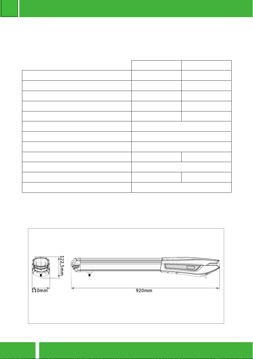
HOME AUTOMATION Z03 - SWING GATE
PG8
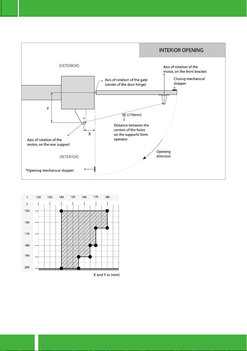
01. Fix the supports.
The rear support must be xed on the pillar
or wall. The front support must be xed on
the gate. Respect the height and distance
measures between the front and rear sup-
ports. It can be xed by using screws with
mechanical bushing or chemical welding
process, because both provide an appro-
priate support
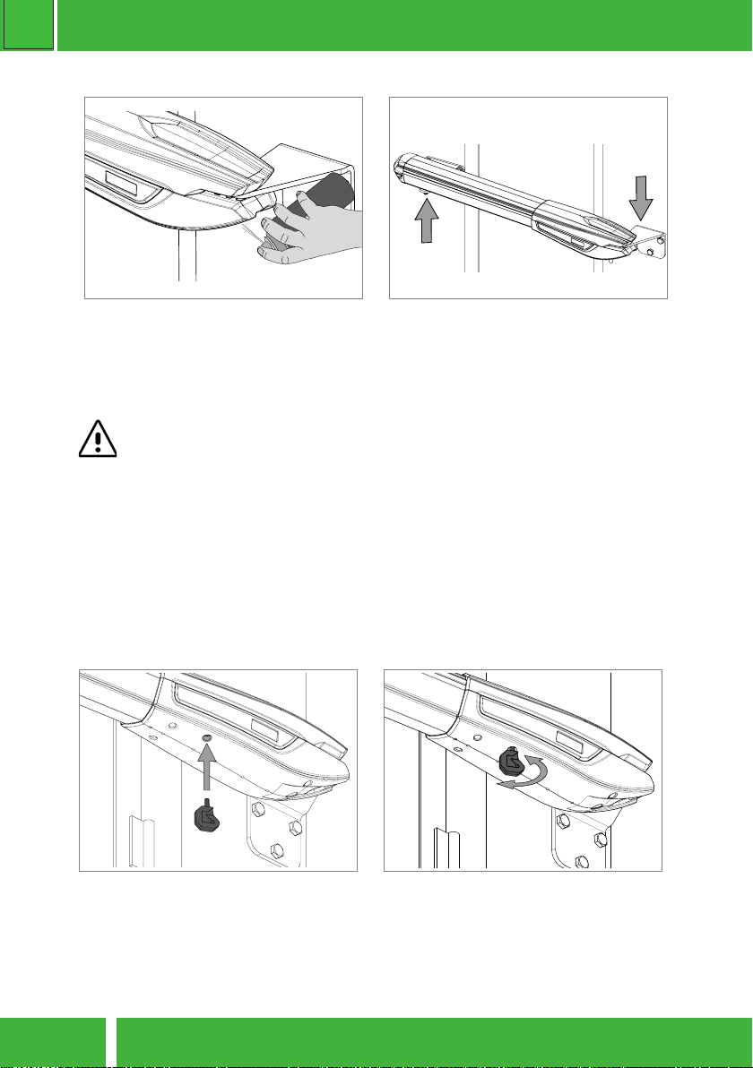
02. Install the operator on the supports
The operator must be placed on both sup-
ports the same me to avoid leaving the
operator suspended by only one of the
supports. To make the task easier, you
should unlock the operator in order to be
able to stretch/retract arm easily,to get the
correct posion for supports.
03. Install the pins removed earlier on each
side with a small amount of lubricant for
lessfricon. Unlock the motor and move
the door manually to see if the door opens
and closes uniformly and correctly, wi-
thout any irregular fricon during its enre
movement. This will ensure that the motor
is not subjected to problems during ope-
raon.
04. Connecng operator to control board
and conguring control devices. With the
operator installed, connect it to control
board for system conguraon (see con-
trol board user manual). Must also con-
gure the desired control devices (transmit-
ters, wall switch, etc.) and other addional
components such as antenna, warning
light, key selector, among others.
It is important to respect this installaon order!
Otherwise, it is not possible to ensure correct installaon and operators may not
work properly!
INSTALLATION STEPS