manuals.online logo
Brands
  1. Home
  2. •
  3. Brands
  4. •
  5. Atag
  6. •
  7. Boiler
  8. •
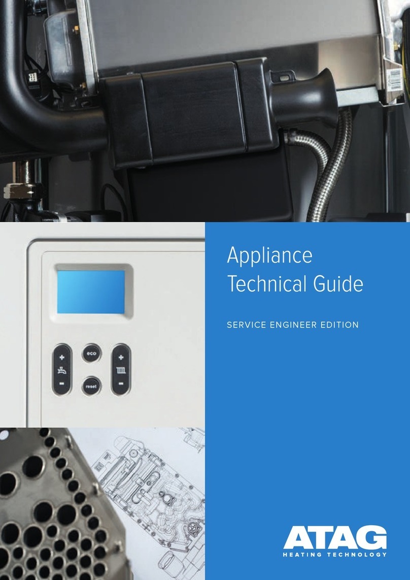
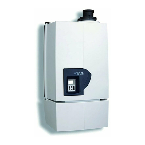
  9. Atag i Series User manual

Atag i Series User manual

ATAG i Series Boiler Fault Finding 02/10/23.
(All models and generations).
1 | P a g e
Contents
1st Generation boiler Page 2
2nd Generation boiler Page 20
3rd Generation boiler Page 41
Wilo Pump LED’s Page 66
Sensor resistances Page 67
Expansion vessel servicing Page 68
2 | P a g e
ATAG i Series 1st generation boiler fault finding.
Fault codes or error:
Fault
Fault
Fault
Other
10
20
28
40
50
61
78
105
110
111
113
117
118
119
128
129
130
133
151
154
164
180
181
SE
Spanner symbol
Pump constantly
running.
Blank display screen
Boiler heating –no
demand & One
Connected.
Error code on ONE
Controller: Code 002 /
003
Random fault codes on
One Controller.
Sensor resistances
Error Sub Codes - 7 Day
Two Channel Plug-In
Digital Programmer
3 | P a g e
10 Description: Outside sensor error
Cause: Outside sensor not present, short-circuited, broken or values outside specifications.
1. If using ATAG One with internet weather:
•Check Wi-Fi signal & re-connect if required.
2. If internet weather is not being used, check if outdoor sensor is in use with boiler.
3. If an outside sensor is fitted and code 10 appears on the boiler, check the following:
•Check the resistance of the outdoor sensor as per the table on page 67 and replace as
required.
•Check whether the cables for the outdoor sensor are connected to the boiler.
•Check that the cable is not damaged, broken or has any poor contacts. Use a multimeter to
confirm continuity of the cables. Replace harness as required.
•Check whether the outdoor sensor is mounted in such a way that it is not affected by
weather influences (sunlight, snow, etc.).
4. If error 10 remains after confirming the outdoor sensor and cables are ok, replace the PCB.
20 Description: Flow sensor error
Cause: The flow sensor T1 value out of range.
1. Check full T1 wiring harness and connectors for signs of damage, corrosion, or loose contact.
2. Use a multimeter to check if T1 sensor resistances are in line with the flow temperatures.
•The flow temperature can be identified using the A menu and A0.
•The resistances can be taken at the connector at the PCB X4 pins 1 & 2. This checks the
wiring harness continuity at same time. Disconnect the connector from PCB 1st to ensure no
additional resistances are given through the PCB. Resistances are found on page 67.
•If the readings are incorrect, disconnect the wiring harness from the sensor and check the
sensor readings without the harness to prove if the sensor or harness is the fault. Replace
part as required.
*Note thermistors may need cleaned and not always replaced*.
3. If error 20 remains after the above has been checked, replace PCB.
28 Description: Flue gas sensor fault
Cause: Flue gas sensor not fitted to our boilers so if 28 fault code appears replace PCB.
4 | P a g e
40 Description: Return sensor error
Cause: The return sensor T2 value out of range.
1. Check full T2 wiring harness and connectors for signs of damage, corrosion, or loose contact.
2. Use a multimeter to check T2 sensor resistances are in line with the return temperatures.
•The return temperature can be identified using the A menu and A1.
•The resistances can be taken at the connector at the PCB X4 pins 3 & 4. This checks the
wiring harness continuity at same time. Disconnect the connector from PCB 1st to ensure no
additional resistances are given through the PCB. Resistances are found on page 67.
•If the readings are incorrect, disconnect the wiring harness from the sensor and check the
sensor readings without the harness to prove if the sensor or harness is the fault. Replace
parts as required.
*Note thermistors may need cleaned and not always replaced*.
3. If error 40 remains after the above has been checked, replace PCB.
50 Description: T3 Hot water sensor error.
Cause: The values of T3 boiler sensor out of specification.
Combi & Economiser boilers.
Cause: The values of the T3 hot water sensor outside specifications.
1. Check full T1 wiring harness and connectors for signs of damage, corrosion, or loose contact.
2. Use a multimeter to check if T3 sensor resistances are in line with the return temperatures and per the table
on page 67.
•The DHW temperature can be identified using the A menu and A2.
•The resistances can be taken at the connector at the PCB X7, pins 8 & 9. This checks the
wiring harness continuity at same time. Disconnect the connector from PCB 1st to ensure no
additional resistances are given through the PCB.
•If the readings are incorrect, disconnect the wiring harness from the sensor and check the
sensor readings without the harness to prove if the sensor or harness is the fault. Replace
parts as required.
*Note thermistors may need cleaned and not always replaced*.
4. If error 50 remains after the above has been checked, replace PCB.
Additional checks for iS & iR boilers with Hot Water Priority.
1. Check the Hot water priority DHW NTC sensor is connected to the boiler.
2. Check the boiler sensor wires for loose contacts and breaks.
3. If the cable has been extended, check the wires at the junction box/block connector.
4. Check if the sensor is installed correctly.
5 | P a g e
61 Description: Bus communication error
Cause: No signal from One controller (contact open).
1. Turn off the power at fused spur, wait 5 seconds and re-establish power. If connection fails to establish,
follow on from point 2.
2. Perform a factory reset on the controller by removing the controller from the wall. Then use a pen or small
screwdriver and press the reset button on the rear of the controller.
3. Check connector at rear of One Controller, ensure pins are not bent.
4. Check continuity of wires from controller to the PCB with a multimeter.
5. Check connection on blue Bus connector at PCB.
6. Check One Controller for power.
a. At the Blue Bus connector in the boiler expect 17 VDC.
b. At the back plate connector of the One Controller, expect 32 VDC with the controller removed.
7. If no power to controller, replace PCB.
8. If power to controller, replace One controller.
78 Description: No pump kick detected/Faulty pressure sensor.
Cause: No pressure increase while the pump is running at full load for 5 seconds. This can be caused by air in the
boiler, a blocked or faulty pressure sensor or a faulty pump. The pressure increase by the pump must be at least 0.1
bar.
1. Check analogue and digital pressure readouts match.
•If these do not match add pressure to the system and check digital gauge reads new pressure.
•Clean sensor if contaminated or replace as required.
2. Use a multimeter to check the wiring harness to the water pressure sensor for continuity from PCB
connector X7 pins 5, 6 & 7, whilst checking connectors are tight and free from damage or corrosion.
•Replace as required.
3. Check DC voltage from pressure sensor back to the PCB on connector X7 pins 5 & 7. The voltage should be
as per the table below. Clean or replace the sensor as required.
4. Check the pump for air and vent the system if required.
•Use the boiler air purge to assist by turning off the power at the fused spur for 5 seconds and then
re-establish the power.
5. Check auto air vent is operating correctly and not contaminated with sludge.
6. Check the operation and voltage of the pump with a demand.
6 | P a g e
•You can force the pump by removing PWM cable at the pump to allow the 230v cable to power the
pump at full speed.
•To do this, ensure safe electrical isolation and then use a 4mm electrical screwdriver to push down
the clip below the PWM connector and gently pull the connector out. Re-establish power to the
boiler and the pump should run at full speed.
7. Confirm 230v from the PCB connector X9 pin 1 & X10 pin 2. If no voltage, replace PCB.
8. Check 230v supplied from the PCB to the pump connector. If voltage at pump connector, replace pump.
9. If no voltage at pump connector, use a multimeter to check the wiring harness for continuity from the PCB
via connector X9 pin 1 & X10 pin 2, whilst checking connectors are tight and free from damage or corrosion.
Replace as required.
10. If 230v side ok, check the pump PWM via the 3-wire cable connection to the pump on PCB connector X1 pins
1&2:
•with the pump off the voltage is +/- 5VDC.
•39% load the voltage is +/- 3VDC.
•61% load the voltage is +/- 1.9VDC.
•100% load the voltage is +/- 0.24VDC.
11. If the above voltages are correct, and the pump does not operate, replace the pump.
12. If the voltages are incorrect, replace the PCB.
13. Check expansion vessel pressure is set correctly as per the manufacturer’s instructions.
14. Check expansion vessel flexi hose is correctly connected with no kinks or blockages.
15. Check the boiler for any blockages or restrictions.
16. After checking all the above points, switch off the power and back on again, allow the boiler to run
automatically through the automatic venting program.
17. If the fault persists, replace the PCB.
105 Description: Venting program active.
Cause: No fault –venting program will run for 7 minutes.
110 Description: Safety temperature exceeded.
Cause: Temperature rise too fast, possible sensor fault or circulation.
1. Check the system for an external heat source such as solar which may affect the return temperature.
2. Confirm flow and return temperatures using the A menu, A0 &A1.
3. Check T1 and T2 resistances in line with temperatures from flow and return temperatures found on page 67.
•Take resistances at the connector X4 on the PCB pins 1 & 2, and pins 3 & 4. This checks the wiring
harness continuity and connectors at same time.
•Check wiring connectors are not loose or corroded.
•Disconnect the connector from PCB to ensure no additional resistances are given through the PCB.
•If readings incorrect, take resistance reading direct from sensor & replace sensor or wiring harness
as required.
*Note sensors may need cleaning and not always replaced*.
7 | P a g e
4. Ensure all air is vented out of the boiler and system.
5. On combi’s, the diverter valve operation may be faulty, check as follows:
•Safely isolate boiler from electrics.
•Remove the motor from the three-way valve and see if the cartridge moves up and down.
•If this doesn't move smoothly and seems to be sticking, replace the cartridge.
6. Check system pipework configuration correct.
7. Ensure all valves on the system and boiler are open.
8. Ensure all air is vented out of the boiler and system.
9. Check system pipework and filters for any blockages or restrictions.
10. Check all installation components are functioning correctly (mixing pumps and 2-way valves, etc.).
11. In the case of a combi, check the plate heat exchanger is not blocked.
12. Check for Voltage at the pump. You can force the pump:
•By removing PWM cable to allow 230v cable to power pump at full speed.
•If pump does not run via above tests check pins on pump not bent –straighten to fix and check
continuity across wiring harness. If all ok and no voltage going to pump, then PCB fault.
•If voltage to pump and all other checks are ok, replace pump.
13. If all the above checks are ok, PCB may be at fault.
*Note * If plastic pipes are used, they must be barrier pipes & UFH must comply with DIN4726-4729. If this is not the
case, system separation must be provided as these pipes are porous & will allow air into the system.
111 Description: Maximum temperature exceeded.
Cause: Possible sensor fault or circulation.
1. Check the system for an external heat source such as solar which may affect the return temperature.
2. Confirm flow and return temperatures using the A menu, A0 &A1.
3. Check T1 and T2 resistances in line with temperatures from flow and return temperatures found on page 67.
•Take resistances at the connector X4 on the PCB pins 1 & 2, and pins 3 & 4. This checks the wiring
harness continuity and connectors at same time.
•Check wiring connectors are not loose or corroded.
•Disconnect the connector from PCB to ensure no additional resistances are given through the PCB.
•If readings incorrect, take resistance reading direct from sensor & replace sensor or wiring harness
as required.
*Note sensors may need cleaning and not always replaced*.
4. Ensure all air is vented out of the boiler and system.
5. On combi’s, the diverter valve operation may be faulty, check as follows:
•Safely isolate boiler from electrics.
•Remove the motor from the three-way valve and see if the cartridge moves up and down.
•If this doesn't move smoothly and seems to be sticking, replace the cartridge.
6. Check system pipework configuration correct.
7. Ensure all valves on the system and boiler are open.
8. Ensure all air is vented out of the boiler and system.
9. Check system pipework and filters for any blockages or restrictions.
10. Check all installation components are functioning correctly (mixing pumps and 2-way valves, etc.).
8 | P a g e
11. In the case of a combi, check the plate heat exchanger is not blocked.
12. Check for Voltage at the pump. You can force the pump:
•By removing PWM cable to allow 230v cable to power pump at full speed.
•If pump does not run via above tests check pins on pump not bent –straighten to fix and check
continuity across wiring harness. If all ok and no voltage going to pump, then PCB fault.
•If voltage to pump and all other checks are ok, replace pump.
13. If all the above checks are ok, PCB may be at fault.
*Note * If plastic pipes are used, they must be barrier pipes & UFH must comply with DIN4726-4729. If this is not the
case, system separation must be provided as these pipes are porous & will allow air into the system.
113 Description: Flue gas sensor (T5) fault.
Cause: Flue gas sensor not fitted to our boilers so if 113 fault code appears replace PCB.
117 Description: Water pressure too high (>3 bar).
Cause: Excessive water pressure in system.
1. Check filling loop is turned off and not passing, replace as required.
2. Check for secondary filling loops in the system and check as per point 1.
3. For combi’s check main water pressure not passing back through plate heat exchanger by isolating cold main
into boiler.
4. Ensure adequate expansion for property.
5. Check expansion vessel flexi hose is correctly connected with no kinks or blockages.
6. Check expansion vessel pressure is set correctly as per the manufacturer’s instructions, and check Shrader
core for leakage.
•Water in the expansion vessel may only be condensation and can be removed using the
expansion vessel service procedure found on page 68.
•Check expansion vessel not leaking, replace as required.
•If the expansion vessel is of adequate size for the property, is not leaking and has been fully
serviced but not holding pressure, replace the expansion vessel.
7. On rare occasions unvented cylinders may pass back to the central heating via a burst coil. Isolate the mains
to confirm.
9 | P a g e
118 Description: Water pressure too low (<0.8 bar to 0.5 bar) or no pump kick
detected.
Cause: Insufficient water pressure in system, blockage in boiler, pump not operating or water pressure sensor faulty.
1. Check analogue and digital pressure readouts match. If these do not match add pressure to the system and
check gauges read new pressure. Replace as required.
2. Check pressure loss patterns with the consumer and if any work has been carried out on the system or
boiler.
3. Check the heating system for leaks (system needs to be cold and may need to be over pressured to force
leak).
4. Ensure adequate expansion for property.
5. Check the boiler for leaks including removal of the siphon to check heat exchanger for leaks.
6. Check the pressure relief valve for leakage.
7. Check expansion vessel flexi hose is correctly connected with no kinks or blockages.
8. Check expansion vessel pressure is set correctly as per the manufacturer’s instructions, and check Shrader
core for leakage.
•Water in the expansion vessel may only be condensation and can be removed using the
expansion vessel service procedure found on page 68.
•Check expansion vessel not leaking, replace as required.
•If the expansion vessel is of adequate size for the property, is not leaking and has been fully
serviced but not holding pressure, replace the expansion vessel.
9. If no obvious leaks are found, isolate boiler from system and leave on test.
•*Note* system must be cold, and pressure set to approx. 1.5 bar before isolating valves from
boiler to system.
•The time required for this test will depend on patterns and amount of pressure loss. (i.e., every 2
days etc.).
119 Description: Link missing on wiring harness.
Cause: Link on PCB connector X2 missing.
1. Check connector connection to PCB.
2. Check link is in pins 4 & 5 on X2.
3. Check wiring harness.
4. Replace parts as required, if all the above is ok, replace PCB.
10 | P a g e
128 Description: Ionisation current too low.
Cause: Ionisation level too low at max fan speed/RPM.
1. Check condensate pipe is clear of blockages and is running freely. Clear as required.
2. Check 230v at gas valve, connections 1 & 3.
a. If the voltage is correct, move to step 3.
b. If there is no voltage at the gas valve, check the PCB is sending 230v to the gas valve from connector
X12, pins 1 & 2. Replace PCB if there is no voltage.
c. If voltage is supplied from the PCB, check the condition of the wiring harness and connectors. Use a
multimeter to confirm continuity throughout the cables. Replace harness if faulty.
3. Check the working pressure at the P1 test point of the gas valve with all gas appliances in the house fully on.
The WP must be no less than 4mb under that of the WP at the gas meter for NG or 2.5mb for LPG.
a. If WP at the meter is under 19mb call National grid or local network to investigate the issue.
b. If under pressure at the boiler, investigate secondary isolation valves, pipe sizing or shale/debris, etc.
in gas pipe.
4. If the working pressure is correct, check the following:
5. Check ionisation current is between 0.8μA & 4μA using the A menu & A8.
6. If ionisation current is ok, proceed to step 7.
a. If ionisation current is too low, check earthing in house with an earth loop impedance tester.
b. If earthing in the property is ok, move to step 8.
7. Check 230v at the ignition transformer, connections 1 & 2 (black wires).
a. If the voltage is correct, move to step 8.
b. If voltage is incorrect at the ignition transformer, check the PCB is sending 230v to the ignition
transformer from connector X12, pins 3 & 4. Replace PCB if there is no voltage.
c. If voltage is supplied from the PCB, check the condition of the wiring harness and connectors. Use a
multimeter to confirm continuity throughout the cables. Replace harness if faulty.
8. Check voltage from the transformer to the electrodes. Using a multimeter, check for between 60-100 volts
AC between both outlet connections of the transformer to an earth connection (the 100 volts should be on
initial startup and then settle to approx. 60V). If voltage incorrect replace transformer or if voltage correct,
proceed to step 9.
9. Check the spark gap and condition of the electrodes, including the ionisation electrode. The spark electrodes
should have a 3 –4mm spark gap and be clean. Adjust spark gap and clean electrodes with a fine sandpaper
if required. If still fails after cleaning and adjustment or is worn out, replace electrodes.
10. Check if the CO/CO2 values are correct.
11. Check the condition of the burner for any debris or cracks, clean or replace as required.
12. Check the non-return valve in the fan is operating correctly, replace as required.
13. Check heat exchanger flue ways are clear of debris. Clean with a soft brush and vacuum cleaner as required.
14. Check boiler for recirculation of products of combustion and repair as required.
15. Check flue length and configuration is correct as per the manufacturer’s instructions.
16. Check flue for breaks and carryout O2 checks to confirm no spillage of products of combustion.
17. Check boiler is set to the correct gas type using the P menu & P5, whilst ensuring LPG boilers have the
correct restrictor fitted at the fan.
18. If all the above have been checked and the fault remains, replace the PCB.
11 | P a g e
129 Description: Fan error.
Cause: Fan does not start up.
1. Ensure safe electrical isolation and remove the PWM cable at the fan (4 wire connector). Re-establish power
to the boiler and the fan should run at full speed.
2. If fan does not run, check for 230v from the PCB connector X11, pins 1 & 2. If no voltage, replace PCB. If
230v present and fan did not run with PWM removed, replace fan.
Expected fan resistances from PWM connection. All pins on the 230v side normally show OL.
Pins 1 - 2
6 MΩ
Pins 2 - 3
15.97 KΩ
Pins 3 - 4
34.72 KΩ
Pins 1 - 3
8.62 MΩ
Pins 2 - 4
18.78 KΩ
x
x
Pins 1 - 4
5 MΩ
x
x
x
x
130 Description: Maximum flue temperature exceeded.
Cause: Flue gas sensor not fitted to our boilers so if 130 fault code appears replace PCB.
133 Description: No flame detected.
Cause: Ignition error.
1. Check condensate pipe is clear of blockages and is running freely. Clear as required.
2. Check 230v at gas valve, connections 1 & 3.
a. If the voltage is correct, move to step 3.
b. If there is no voltage at the gas valve, check the PCB is sending 230v to the gas valve from connector
X12, pins 1 & 2. Replace PCB if there is no voltage.
c. If voltage is supplied from the PCB, check the condition of the wiring harness and connectors. Use a
multimeter to confirm continuity throughout the cables. Replace harness if faulty.
3. Check the working pressure at the P1 test point of the gas valve with all gas appliances in the house fully on.
The WP must be no less than 4mb under that of the WP at the gas meter for NG or 2.5mb for LPG.
a. If WP at the meter is under 19mb call National grid or local network to investigate the issue.
b. If under pressure at the boiler, investigate secondary isolation valves, pipe sizing or shale/debris, etc.
in gas pipe.
4. If the working pressure is correct, check the following:
5. Check ionisation current is between 0.8μA & 4μA using the A menu and A8.
6. If ionisation current is ok, proceed to step 7.
a. If ionisation current is too low, check earthing in house with an earth loop impedance tester.
b. If earthing in the property is ok, move to step 8.
7. Check 230v at the ignition transformer, connections 1 & 2 (black wires).
12 | P a g e
a. If the voltage is correct, move to step 8.
b. If voltage is incorrect at the ignition transformer, check the PCB is sending 230v to the ignition
transformer from connector X12, pins 3 & 4. Replace PCB if there is no voltage.
c. If voltage is supplied from the PCB, check the condition of the wiring harness and connectors. Use a
multimeter to confirm continuity throughout the cables. Replace harness if faulty.
8. Check voltage from the transformer to the electrodes. Using a multimeter, check for between 60-100 volts
AC between both outlet connections of the transformer to an earth connection (the 100 volts should be on
initial startup and then settle to approx. 60V). If voltage incorrect replace transformer or if voltage correct,
proceed to step 9.
9. Check the spark gap and condition of the electrodes, including the ionisation electrode. The spark electrodes
should have a 3 –4mm spark gap and be clean. Adjust spark gap and clean electrodes with a fine sandpaper
if required. If still fails after cleaning and adjustment or is worn out, replace electrodes.
10. Check if the CO/CO2 values are correct.
11. Check the condition of the burner for any debris or cracks, clean or replace as required.
12. Check the non-return valve in the fan is operating correctly, replace as required.
13. Check heat exchanger flue ways are clear of debris. Clean with a soft brush and vacuum cleaner as required.
14. Check boiler for recirculation of products of combustion and repair as required.
15. Check flue length and configuration is correct as per the manufacturer’s instructions.
16. Check flue for breaks and carryout O2 checks to confirm no spillage of products of combustion.
17. Check boiler is set to the correct gas type using parameter P5, whilst ensuring LPG boilers have the correct
restrictor fitted at the fan.
18. If all the above have been checked and the fault remains, replace the PCB.
151 Description: Fan not detected/iR boiler flow error.
Cause: PCB not recognising fan via PWM or fan fault. If for 25 seconds, the RPM is not within tolerance the fault code
151 will be given. (Normally PCB at fault however follow the below to prove).
*If iR boiler flow switch has an open connection during the ignition - for guidance, see below fan speed table after
point 5*.
1. Reset boiler. If fault 151 appears again, replace PCB. If fault clears proceed to step 2.
2. Ensure safe electrical isolation and remove the PWM cable at the fan (4 wire connector). Re-establish power
to the boiler and the fan should run at full speed.
3. If fan does not run, check for 230v from the PCB connector X11, pins 1 & 2. If no voltage, replace PCB.
4. If 230v present and fan did not run with PWM removed check wiring harness for continuity, if ok, replace
fan.
Expected fan resistances from PWM connection. All pins on the 230v side normally show OL.
Pins 1 - 2
6 MΩ
Pins 2 - 3
15.97 KΩ
Pins 3 - 4
34.72 KΩ
Pins 1 - 3
8.62 MΩ
Pins 2 - 4
18.78 KΩ
x
x
Pins 1 - 4
5 MΩ
x
x
x
x
5. If the fan runs, check fan speed via the below table and A menu, A9. If no speed displayed replace PCB or if
speed incorrect replace Fan.
13 | P a g e
If iR boiler, pump has started and flow switch has made, then the flow has dropped out causing the flow switch to
connection to break. Usually, system related.
1. Check the pump for air and vent the system if required.
•Use the boiler air purge to assist by turning off the power at the fused spur for 5 seconds and
then re-establish the power.
2. Check external pump operating properly/strong enough.
3. Check auto air vent is operating correctly and not contaminated with sludge.
4. Check all isolation valves on boiler and system are open.
5. Check system design.
6. Check system for blockages.
7. To check the flow switch, disconnect it from the boiler and using a multimeter across the connections, check
for continuity when making the switch and OL when switch breaks. Only replace the flow switch when all
the above has been checked and confirmed.
154 Description: Flow temp increases too fast and high ∆T.
Cause: System flow, pump, or sensor fault.
1. Check the system for an external heat source such as solar which may affect the return temperature.
2. Confirm flow and return temperatures using the A menu, A0 & A1.
3. Check T1 and T2 resistances in line with temperatures from flow and return temperatures found on page 67.
•Take resistances at the PCB connector X4, pins 1&2 (T1) and 3&4 (T2). This checks the wiring
harness continuity and connectors at same time.
•Check wiring connectors are not loose or corroded.
•Disconnect the connector from PCB to ensure no additional resistances are given through the PCB.
•If readings incorrect, take resistance reading direct from sensor & replace sensor or wiring harness
as required.
•Note sensors may need cleaning and not always replaced.
14 | P a g e
4. On combi’s, the diverter valve operation may be faulty, check as follows:
•Safely isolate boiler from electrics.
•Remove the motor from the three-way valve and see if the cartridge moves up and down.
•If this doesn't move smoothly and seems to be sticking, replace the cartridge.
5. Check system pipework configuration correct.
6. Ensure all valves on the system and boiler are open.
7. Ensure all air is vented out of the boiler and system.
8. Check system pipework and filters for any blockages or restrictions.
9. Check all installation components are functioning correctly (mixing pumps and 2-way valves, etc.).
10. In the case of a combi, check the plate heat exchanger is not blocked.
11. Check for Voltage at the pump:
•You can force the pump by removing the PWM cable to allow 230v cable to power pump at full
speed.
•If pump does not run via above test check, check 230v across PCB connectors X9, pin 1, and X10
pin 2. If no voltage present, replace PCB.
•If voltage present check pins on pump PWM connector are not bent –straighten to fix if
required, and check continuity of wiring harness.
•Check the pump PWM via the 2-wire cable connection to the pump on PCB connector X1 pin
1&2:
1. with the pump off the voltage is +/- 9VDC.
2. On pump startup the voltage is +/- 1VDC.
3. Pump overrun approx. 4.5VDC
4. Normal running approx. 4.3VDC
•If above DC voltages are incorrect, replace PCB.
•If voltage to pump and all other checks are ok, replace pump.
*Note * If plastic pipes are used, they must be barrier pipes & UFH must comply with DIN4726-4729. If this is not the
case, system separation must be provided as these pipes are porous & will allow air into the system.
164 Description: iR boiler Flow error.
Cause: flow switch has an open connection during the operation of the boiler or before starting up. Usually, system
related.
1. Check the pump for air and vent the system if required.
•Use the boiler air purge to assist by turning off the power at the fused spur for 5 seconds and
then re-establish the power.
2. Check external pump operating properly/strong enough.
3. Check auto air vent is operating correctly and not contaminated with sludge.
4. Check all isolation valves on boiler and system are open.
5. Check system design.
6. Check system for blockages.
7. To check the flow switch, disconnect it from the boiler and using a multimeter across the connections, check
for continuity when making the switch and OL when switch breaks. Only replace the flow switch when all
the above has been checked and confirmed.
15 | P a g e
180 Description: Boiler is in chimney sweep (service) mode.
Cause: No fault. Chimney sweep will run for 15 minutes and clear. If doing this constantly, replace PCB.
181 Description: Boiler coming out of chimney sweep (service) mode.
Cause: No fault. This code shows when boiler comes out of chimney sweep mode. If doing this constantly, replace
PCB.
SE Description: Time error
Cause: Timer needs reset via boiler display.
1. Push the DHW minus button, the Reset button, and the CH minus button simultaneously.
Spanner symbol Description: Blocking error or service mode.
Cause: The system pressure is low, or the boiler is in service mode. This will clear when the pressure is addressed, or
the boiler is out of service mode.
Pump constantly running.
Cause: Frost protection active or pump PWM fault. Sometimes linked with 118 fault codes, if so PWM fault.
1. If a frost symbol is present in the boiler display, follow from point 2. If there is no frost symbol on the
display, follow from point 4.
2. Check if boiler has been put into a manual frost protection. This can be turned off by pressing both minus
buttons together for 6 seconds. The frost symbol should disappear. If not, proceed to step 3.
3. If the temperature is less than 5 °C, then the internal frost protection is active.
i. Confirm the resistance of the T1 flow sensor as per the table on page 67 and replace as
required.
ii. Confirm the wiring harness continuity and contacts are ok. Replace if required.
iii. If the above checks are OK, replace the PCB.
4. Check the PWM signal to the pump is ok by completing the following:
a. Safely isolate the boiler and remove the PWM cable from the pump. Check the pins are not bent –if
bent use a small screwdriver to straighten.
b. Check pump position in relation to the PCB casing. If this is too close it can put pressure on the
PWM connector causing a loose connection. This is usually diagnosed by bring the PCB housing
down towards you and the pump may stop –adjust the pump position if required.
16 | P a g e
5. Check for Voltage at the pump:
•You can force the pump by removing the PWM cable to allow 230v cable to power pump at full
speed.
•If pump does not run via above test check, check 230v across PCB connectors X9, pin 1, and X10
pin 2. If no voltage present, replace PCB.
•If voltage present check pins on pump PWM connector are not bent –straighten to fix if
required, and check continuity of wiring harness.
•Check the pump PWM via the 2-wire cable connection to the pump on PCB connector X1 pin
1&2:
I. with the pump off the voltage is +/- 9VDC.
II. On pump startup the voltage is +/- 1VDC.
III. Pump overrun approx. 4.5VDC
IV. Normal running approx. 4.3VDC
6. If the voltages are incorrect, replace the PCB.
7. If the voltages are correct, replace the pump.
Blank display screen.
Cause: No power to boiler, internal fuses blown, display fault, PCB fault, fan or pump faults caused PCB to blow.
1. Check fuse at fused spur.
2. Check 230v into boiler.
3. Check continuity of fuses F1 & F2. Replace as required.
•These fuses protect both the live and neutral circuits only and are not specific to components or
internal circuits.
•Note the boiler is not polarity sensitive however polarity must be correct for safety.
4. Check fan resistances per 151 fault code. Replace fan as required.
•PCB will also need changed as fan has taken out board.
5. If fan ok, check pump for smell of burning. Replace pump and PCB.
6. If fan and pump are ok, replace PCB.
Boiler heating –no demand & One Control connected.
Cause: Boiler is still operating with last command from controller, controller now lost signal to boiler.
1. Perform a factory reset on the controller by removing the controller from the wall. Then use a pen or small
screwdriver and press the reset button on the rear of the controller.
2. If the reset does not work, replace the One Controller.
17 | P a g e
Error code on One Controller 002/003.
Cause: No fault - These codes show the boiler is in chimney sweep mode (service mode), the same as codes 180 &
181.
Random fault codes on One Controller.
Cause: Faulty battery or controller.
1. Check battery for swelling. If swollen, replace the battery.
2. If battery is OK, perform a factory reset on the controller by removing the controller from the wall. Then use
a pen or small screwdriver and press the reset button on the rear of the controller.
3. If the reset does not work, replace the One Controller.
LMU Sub codes.
LMU sub codes that can be displayed on the plug-in digital programmer and description of the codes on the ONE
controller and notifications that are shown on the app.
If an error code is still on the display of the boiler e.g., 129, then you can plug in the digital programmer to the blue
BUS connection on the back of the board. If the error code has been reset and the display says ‘OK’ then you will not
be able to see the error sub code.
So, when you plug in the digital programmer the boiler display will show e.g., 129 and the digital programmer will
power up and display an error sub code e.g., 2, which in this case is ‘Fan failure low rpm’. This means the rpm of the
fan was too low and you just replace fan.
Therefore, the plug-in digital programmer can be used as a diagnostic tool to help indicate the fault on the boiler
with the displayed sub codes.
*Codes on next 2 pages*.
18 | P a g e
19 | P a g e

This manual suits for next models

17

Other Atag Boiler manuals

Atag IC series User manual

Atag

Atag IC series User manual

Atag iC 24 Release note

Atag

Atag iC 24 Release note

Atag i28C Release note

Atag

Atag i28C Release note

Atag Q 51C User manual

Atag

Atag Q 51C User manual

Atag IC series User manual

Atag

Atag IC series User manual

Atag XL140 Release note

Atag

Atag XL140 Release note

Atag A200S Release note

Atag

Atag A200S Release note

Atag Premier E-SHR 15 User guide

Atag

Atag Premier E-SHR 15 User guide

Atag E 22S User guide

Atag

Atag E 22S User guide

Atag A200S Release note

Atag

Atag A200S Release note

Atag Q 25S Release note

Atag

Atag Q 25S Release note

Atag IS 12 Release note

Atag

Atag IS 12 Release note

Atag XL-W Series User manual

Atag

Atag XL-W Series User manual

Atag 41-310-12 User manual

Atag

Atag 41-310-12 User manual

Atag Blauwe Engel S-HR User manual

Atag

Atag Blauwe Engel S-HR User manual

Atag iSteel Series User manual

Atag

Atag iSteel Series User manual

Atag XL-F Series User manual

Atag

Atag XL-F Series User manual

Atag Q 25S Release note

Atag

Atag Q 25S Release note

Atag QR Series User manual

Atag

Atag QR Series User manual

Atag Blauwe Engel S-HR Series User guide

Atag

Atag Blauwe Engel S-HR Series User guide

Atag iC Economiser 27 Quick start guide

Atag

Atag iC Economiser 27 Quick start guide

Atag A-Series User manual

Atag

Atag A-Series User manual

Atag XL75F Release note

Atag

Atag XL75F Release note

Atag iR 12 Release note

Atag

Atag iR 12 Release note

Popular Boiler manuals by other brands

Osby Parca EL 360 Eco Installation and operating instructions

Osby Parca

Osby Parca EL 360 Eco Installation and operating instructions

IDEAL Classic FF 350 P user guide

IDEAL

IDEAL Classic FF 350 P user guide

Glowworm 30ci plus Instructions for use installation and servicing

Glowworm

Glowworm 30ci plus Instructions for use installation and servicing

Glowworm Compact 28c-AS/1 operating instructions

Glowworm

Glowworm Compact 28c-AS/1 operating instructions

Power Max OV 140 P Series Installation and servicing instructions

Power Max

Power Max OV 140 P Series Installation and servicing instructions

CleaverBrooks S Operation and maintenance manual

CleaverBrooks

CleaverBrooks S Operation and maintenance manual

Glowworm Hideaway 40B FF Instructions for use

Glowworm

Glowworm Hideaway 40B FF Instructions for use

Glowworm Energy 35 Store-A Installation and maintenance instructions

Glowworm

Glowworm Energy 35 Store-A Installation and maintenance instructions

Johnson & Starley RenoXtra 30CA Installation, maintenance and servicing instructions

Johnson & Starley

Johnson & Starley RenoXtra 30CA Installation, maintenance and servicing instructions

AER BMK Series Installation and start-up manual

AER

AER BMK Series Installation and start-up manual

Proficook PC-WKS 1108 instruction manual

Proficook

Proficook PC-WKS 1108 instruction manual

Glowworm Economy Plus 60F Instructions for use, installation & servicing

Glowworm

Glowworm Economy Plus 60F Instructions for use, installation & servicing

Alfa Plam COMMO COMPACT 32 Installation, operation and maintenance manual

Alfa Plam

Alfa Plam COMMO COMPACT 32 Installation, operation and maintenance manual

CleaverBrooks ClearFire CFH Operation, service and parts manual

CleaverBrooks

CleaverBrooks ClearFire CFH Operation, service and parts manual

Glowworm Ultracom 24cxi Instructions for use installation and servicing

Glowworm

Glowworm Ultracom 24cxi Instructions for use installation and servicing

Viessmann VITODENS 343-F WS4A Installation and service instructions

Viessmann

Viessmann VITODENS 343-F WS4A Installation and service instructions

Glowworm MicraCom 24c-AS/1 operating instructions

Glowworm

Glowworm MicraCom 24c-AS/1 operating instructions

AER KN-COSMXTR-BCA user guide

AER

AER KN-COSMXTR-BCA user guide

manuals.online logo
manuals.online logoBrands
  • About & Mission
  • Contact us
  • Privacy Policy
  • Terms and Conditions

Copyright 2025 Manuals.Online. All Rights Reserved.