ATB AQUA 8 Manual

Innovations for clean water
AQUA 8
Installation/Operating Instructions

Installation/Operating Instructions AQUA 8
ATB WATER GmbH, üdstraße 2, 32457 Porta Westfalica, Germany, www.atbwater.com
Version: 14.01.2022 / Page 2 of 19
!!! IMPORTANT !!!
PRIOR TO USING THE UNIT
Anybody involved MU T imperatively read and fully understand the unit’s O&M manual.
It is most important that the O&M manuals remain with the operator for future reference.
GENERA
No foreign objects such as hard materials, plastic bags, etc... are allowed in the basins.
These objects can cause extensive damage and/or for example create unbalance to the
impeller.
P EASE NOTE
This O&M manual is valid for both, the AQUA 8-M with single-phase alternating current
motor and for the AQUA 8-T with high-voltage current motor. Instructions which refer to
the AQUA 8 in general are valid for both versions of the product.

Installation/Operating Instructions AQUA 8
ATB WATER GmbH, üdstraße 2, 32457 Porta Westfalica, Germany, www.atbwater.com
Version: 14.01.2022 / Page 3 of 19
Contents
1 Introduction ............................................................................................................... 4
1.1 General and afety Information ................................................................................ 4
1.2 Product characteristics ............................................................................................. 4
2 Installation and Commissioning .............................................................................. 5
2.1 Installation instructions ............................................................................................. 5
2.2 Electrical connection and start-up ............................................................................. 6
3 Maintenance .............................................................................................................. 8
3.1 AQUA 8-M ................................................................................................................ 8
3.1.1 Periodical check ............................................................................................... 8
3.1.2 Changing the propeller .................................................................................... 9
3.2 AQUA 8-T ............................................................................................................... 10
3.2.1 Maintenance requirements and intervals ..................................................... 10
3.2.2 Inspections performed on-site on a regular base: ...................................... 10
3.2.3 Overhaul .......................................................................................................... 11
3.2.4 Service in case of alarm ................................................................................ 11
3.2.5 Inspect the stator housing............................................................................. 11
3.2.6 Change the propeller ..................................................................................... 12
3.2.7 Change the oil ................................................................................................. 14
ENC OSURE I: Technical Data ..................................................................................... 17
AQUA 8-M .................................................................................................................... 17
AQUA 8-T ..................................................................................................................... 18
ENC OSURE II: Declaration of Conformity ................................................................. 19

Installation/Operating Instructions AQUA 8
ATB WATER GmbH, üdstraße 2, 32457 Porta Westfalica, Germany, www.atbwater.com
Version: 14.01.2022 / Page 4 of 19
1 Introduction
1.1 General and Safety Information
The AQUA 8 surface aerator has been developed for the aeration and agitation of wastewater in
wastewater treatment plants based on the activated sludge process. The machine is suitable for
mechanically pretreated, domestic wastewater and commercial wastewater, so far as it is
comparable with domestic wastewater, which are free of solid and fibrous matter. Any other use is
not allowed and leads to the loss of the guarantee and liability. The aerator may not run dry.
Changes in the device or the opening of the engine part are prohibited. The aerator may never be
pulled, transported or fastened at the connecting cable. Avoid absolutely abrasions and defects in
the connecting lead. Do not operate any equipment that has a damaged connecting line /
connection cable or plug, which indicates a faulty function, has been dropped or has been
damaged in any way.
Only the manufacturer or an authorized technician may repair defective engines. Moreover, only
original spare parts may be used. All other changes in the device lead to the loss of the guarantee
claims.
With the intended employment there are no hazards emanating from the equipment. Nationally
applicable regulations as well as technical data are to be observed.
Explanation of the warnings used:
Attention! Hazard due to Hazard due to
rotating parts electrical voltage
1.2 Product characteristics
Agitation and aeration using only one unit
Pre-treatment in a settling facility required
Process easy on activated sludge flocs
Maximum surface 7.5m², maximum tank diagonal 3.5m
Minimum water depth 1m, maximum water depth 2.5m
eparable float for ø 600mm tank openings
Motor with propeller individually removable
ingle phase motor for 230V, 50/60Hz with condenser (AQUA 8-M) and three-phase
alternating current motor for D-230/Y-400V, 50/60Hz (AQUA 8-T)
Motor protection class IP68
Motor insulation class F
Motor completely submerged, thus even ambient conditions
All components made from AI I304 or PE
15m connection cable with 5m protective hose (AQUA 8-M) resp. 10m connection
cable (AQUA 8-T)
High energy efficiency
imple handling
Low maintenance

Installation/Operating Instructions AQUA 8
ATB WATER GmbH, üdstraße 2, 32457 Porta Westfalica, Germany, www.atbwater.com
Version: 14.01.2022 / Page 5 of 19
2 Installation and Commissioning
2.1 Installation instructions
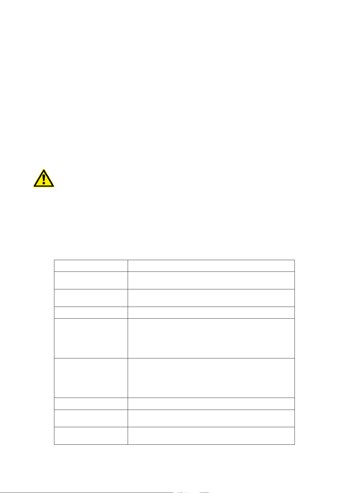
The aeration unit AQUA 8 consists of a
separable float with suction pipe (1) and the
motor unit with propeller and distributor (2). All
materials are made of V2A stainless steel or
plastic and are thus suitable for use in
wastewater.
For tank openings (3) smaller than 800mm, the
two-part float can be opened on one side and
inserted into the tank. It must then be screwed
back into the tank. The clear diameter of the tank
opening should be at least 600mm. When
delivered, both halves of the float are usually
only screwed together hand tight.
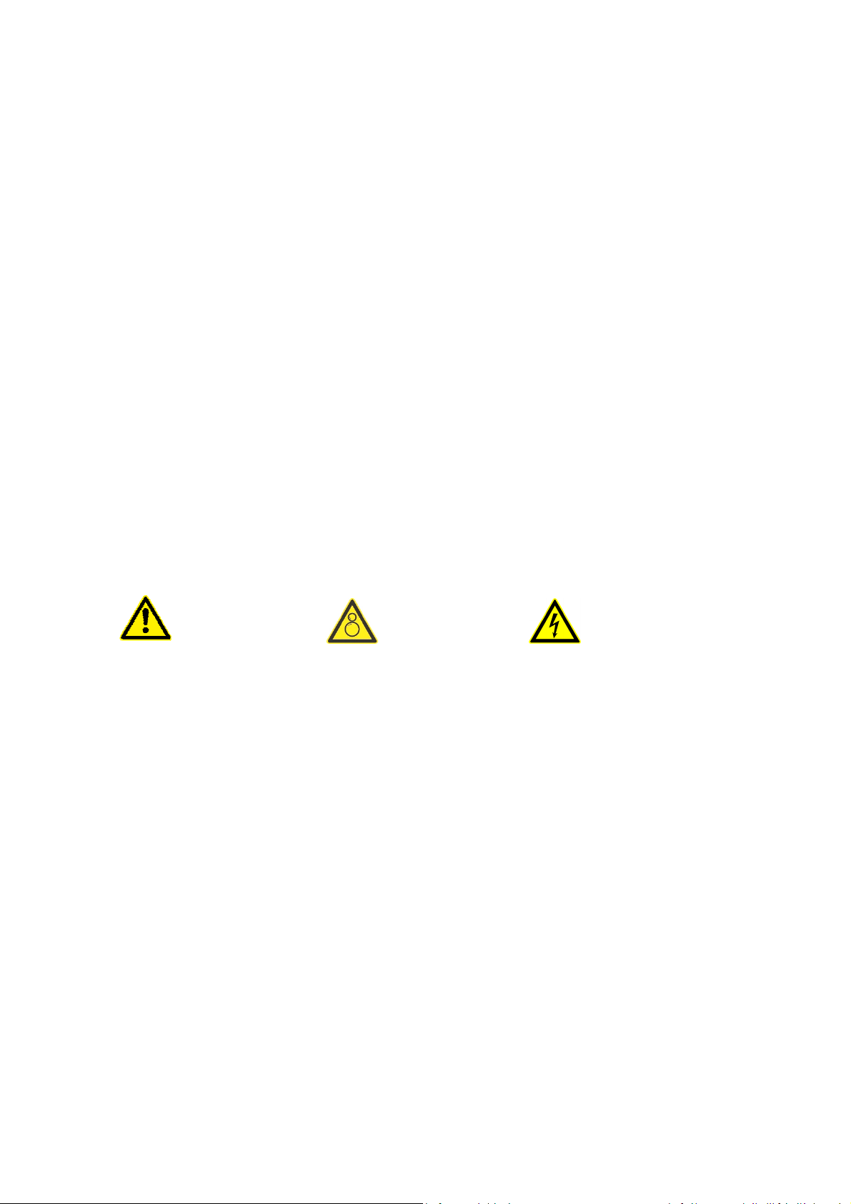
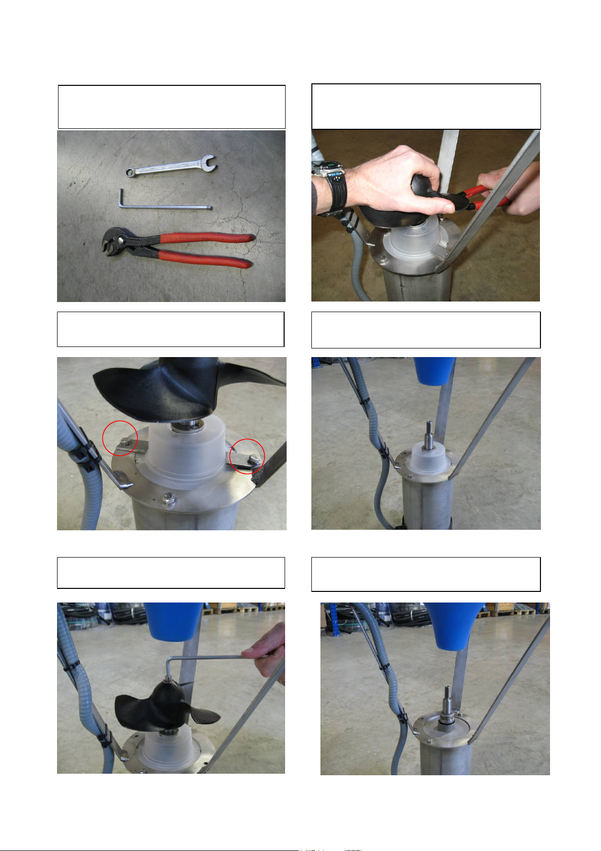
The intake pipe is to be screwed together with
the float to form a unit. To do this, turn the
pontoon upside down and screw the stainless-
steel pipe to the float using the retaining
brackets. To do this, use the corresponding
threaded inserts on the pontoon and the drill
holes in the stainless-steel pipe.
The float with suction pipe is then positioned on
the tank bottom centrally under the maintenance
opening.
Then the positions for the heavy-duty anchors of
the guide chains are measured in the area of the
tank opening so that the chains can run vertically
at a distance of approx. 75 cm through the guide
elements on the float and can hang down to the
tank bottom.
For the assembly of the guide chains, the
turnbuckles are turned up to maximum length
and fastened to the heavy-duty anchors with ring
nuts and shackles. The vertically hanging guide
chains determine the lower fixing points. The
lower heavy-duty anchors are now mounted here
and connected to the lower chain ends. The
chain must be shortened to the required length.
Attention Free chain ends can be sucked in by
the aerator and cause damage.
The guide chains are then tensioned over the
turnbuckles and fixed with the lock nut.

Installation/Operating Instructions AQUA 8
ATB WATER GmbH, üdstraße 2, 32457 Porta Westfalica, Germany, www.atbwater.com
Version: 14.01.2022 / Page 6 of 19
The motor unit with the baffle plate is not irmly connected to the float and can be loosely inserted at
the end of assembly.
For maintenance purposes, the motor unit can be removed from the tank via the tank opening
using a loosely enclosed catch chain.
The tightness of all screws must be checked and retightened.
2.2 Electrical connection and start-up
A professional check before commissioning must make sure that the demanded
electric preventive measures exist. A Residual-Current-Device (RCD) with a releasing
nominal current to 30 mA is prescribed. A pre-fuse of 6A is recommended.
The tension given on the type plate must agree with the power supply voltage on site.
The electrical connection must correspond to the wiring diagram from the documents to
the control unit.
The aerator may not run dry. The tank has to be filled up to the minimal water level with
water before commissioning (at least 1 m).
Before switching the power on, be sure that no people can be endangered by the
rotating propeller and the propeller can work unhindered. The motor part should be
inserted into the float and no objects should float in the water that can be sucked in by
the AQUA 8.
Only AQUA 8-M:
The motor is a single-phase alternating current motor with integrated operating
capacitor. The electrical connection of the three wired motor cable with phase (L),
neutral (N) and potential earth (PE) should be carried out by a skilled craftsman. The
nominal current consumption of the motor is approx. 4.8 – 5.2A.
Only AQUA 8-T:
The motor is a three-phase alternating current motor for DOL operation. For the
electrical connection a 6 wires cable is to be used: 3xphases (L1, L2, L3), one ground
wire (PE), 2 wires for the thermal protection contact (NC). The wiring should be carried
out by a skilled craftsman. The current consumption of the motor is approx. 3,8A in
400V star-operation or 5,8A in 230V delta-operation.
The motor of the AQUA 8-T is always equipped with temperature sensors (between T1
and T2) which are integrated in the stator.
The following applies to the engine monitoring equipment:

Installation/Operating Instructions AQUA 8
ATB WATER GmbH, üdstraße 2, 32457 Porta Westfalica, Germany, www.atbwater.com
Version: 14.01.2022 / Page 7 of 19
The stator is equipped with temperature sensors connected in series, which
trigger the alarm in case of excess temperature.
The temperature sensors respond at 140 °C.
The sensors must be connected to a suitable monitoring assembly (closed under
normal condition and open when temperature is exceeded)
The monitoring equipment must be designed so that an automatic restart is
impossible.
Connection and start of the AQUA 8-T:
Connect the main lines (L1, L2, L3 and ground) to the control unit according to
the wiring diagram.
Connect the control conductors for temperature T1 and T2 to their monitoring
equipment.
tart the motor briefly to check the direction of rotation. The correct direction of
rotation of the propeller is counterclockwise when looking at the engine from the
propeller.
The maximum permissible number of starts per hour is 30.
If the device is supplied as a component part of an AQUAMAX
®
-PRO system, the
motor can be started in manual mode via the control unit. In this operating mode, the
current consumption is shown on the display.

Installation/Operating Instructions AQUA 8
ATB WATER GmbH, üdstraße 2, 32457 Porta Westfalica, Germany, www.atbwater.com
Version: 14.01.2022 / Page 8 of 19
3 Maintenance
3.1 AQUA 8-M
3.1.1 Periodical check
The aerator / agitator AQUA 8 works nearly maintenance-free. Within the scope of a servicing of
the whole installation merely the device is to be cleaned and to examine for damages. For this it is
necessary to pull the engine part out of the tank.
Attention – first disconnect the plant from power supply! Aerator may not be pulled out
on the motor cable. Use the enclosed chain with hook (threading in caching ear).
At least once a year the smooth run of the propeller and the state of the thick flange in
the engine is to be checked.
After cleaning the motor, the current consumption should be checked in manual
operation

Installation/Operating Instructions AQUA 8
ATB WATER GmbH, üdstraße 2, 32457 Porta Westfalica, Germany, www.atbwater.com
Version: 14.01.2022 / Page 9 of 19
3.1.2 Changing the propeller
Tools needed:
Water-pump-pliers, 10mm screw wrench,
5mm
hexagonal socket
-
key
2. Remove the hexagonal screw
3. Hold on the shaft with the water-pump-
pliers and unfasten the propeller manually
against clockwise
5. Remove carefully any debris from shaft
and bearings.
1. Loose the tabs with a 10mm screw
wrench
4. If present, pull the protective cap
upwards

Installation/Operating Instructions AQUA 8
ATB WATER GmbH, üdstraße 2, 32457 Porta Westfalica, Germany, www.atbwater.com
Version: 14.01.2022 / Page 10 of 19
3.2 AQUA 8-T
3.2.1 Maintenance requirements and intervals
Following control and maintenance work must be carried out on a regular base:
After 4.000 working hours or after 1 years of operation, whichever comes first:
Check the propeller for wear
Clean device
Check the running values of the voltage and amperage (in manual operation mode and with
aerator submersed). Value of the current should be around 3,8 A
General inspection
Check for wear. If necessary, replace
Check the consumption of the zinc anode
Attention – Always disconnect and lock out power before servicing! Do not pull out the
motor part with the power cable. Use for pulling out the delivered chain with hook.
After 12.000 operating hours or 3 years of operation, whichever comes first (overhaul :
Maintenance works as specified above
Replacement of key components
This maintenance works have to be carried out at an authorized workshop!
3.2.2 Inspections performed on-site on a regular base:
Service item Action
Power cable Check for damage. If necessary, replace the power cable.
Check the cable support. If necessary, adjust it.
Oil housing Check the oil. If necessary, change it.
Replace the O-rings of the filling plug.
Control cabinet Check the power connections.
tator protection
Check the thermal contacts.
Normally closed circuit, interval 0–1 ohm.
Check the resistance of the thermistors.
The correct value is between 20–250 ohm.
The maximum measuring voltage is 2 VDC.
Insulation
Use a megger maximum 1000 V.
Check that the resistance between the ground (earth) and
phase lead is more than
5 megohms.
Do a phase-to-phase resistance check, maximum 50 ohm.
Motor condition Check the running values of the voltage and amperage.
Propeller Check for wear. If necessary, replace parts.
Check the direction of the rotation.
Zinc anode If applicable, check the consumption. If necessary, replace
the zinc anode.

Installation/Operating Instructions AQUA 8
ATB WATER GmbH, üdstraße 2, 32457 Porta Westfalica, Germany, www.atbwater.com
Version: 14.01.2022 / Page 11 of 19
3.2.3 Overhaul
The overhaul is performed at an authorized workshop. Maintenance as specified above plus:
Service item Action
Bearings Replace the bearings.
O-rings Replace the O-rings.
Mechanical seals Replace the mechanical seals.
Junction box Check that the junction box is clean and dry.
Check the power connections.
3.2.4 Service in case of alarm
Alarm source Action
FL
Check the connection chamber for any leakage and drain if
necessary.
Check mechanical seals and O-rings and replace any
damaged seals with new ones.
Thermal contact
Check the connections and the electrical motor.
Check the temperature and viscosity of the mixed liquid.
Check that the position is according to the installation
requirements
Overload protection Check that the propeller can rotate freely.
3.2.5 Inspect the stator housing
A screwdriver is required for this procedure.
1) Attach the mixer in a screw vice. Use the lifting handle as an attachment.
2) Loosen and remove the inspection plug and O-ring.
3) Undo the mixer from the screw vice and turn the mixer upside down over an oil tray.
4) If any liquid runs out, replace the seal.

Installation/Operating Instructions AQUA 8
ATB WATER GmbH, üdstraße 2, 32457 Porta Westfalica, Germany, www.atbwater.com
Version: 14.01.2022 / Page 12 of 19
3.2.6 Change the propeller
CAUTION: Cutting Hazard
harp edges. Wear protective clothing
.
The following special tools are needed for this procedure:
• Hexagon socket wrench (13 mm)
• Hexagon socket head cup wrench (6 mm)
• crewdriver
• Tool 82 93 11
• Torque wrench (6 mm)
Remove the jet ring, guiding claw, and propeller
The following tools are used in this procedure:
• Hexagon socket wrench (13 mm)
• Hexagon socket head cup wrench (6 mm)
• crewdriver
1) Loosen the guiding claw
a) Remove the screws, washers, and nuts
b) Remove the guiding claw
2) Remove the propeller
a) Remove the plastic plug.
b) Loosen the central screw and washer.
c) Remove the propeller together with screw and washer.
3) Check for seal leakage:
a) Attach the mixer in a screw vice.
Use the lifting handle as an attachment.
b) Loosen and remove the inspection plug and O-ring.

Installation/Operating Instructions AQUA 8
ATB WATER GmbH, üdstraße 2, 32457 Porta Westfalica, Germany, www.atbwater.com
Version: 14.01.2022 / Page 13 of 19
c) Undo the mixer from the screw vice and turn the mixer upside down over an oil tray.
d) If any liquid runs out, replace the seal.
Assemble the propeller and guiding claw
Before following this procedure, you must fill the oil. ee “Fill the oil”
The following tools are used in this procedure:
• Hexagon socket wrench (13 mm)
• Hexagon socket head cup wrench (6 mm)
• trap mounting tool 82 93 11
• Torque wrench (6 mm)
1) Mount the protective ring.
2) Press it down towards the oil housing until it bottoms out.
3) Put on the strap and tighten it 7±2 mm from the bottom edge

Installation/Operating Instructions AQUA 8
ATB WATER GmbH, üdstraße 2, 32457 Porta Westfalica, Germany, www.atbwater.com
Version: 14.01.2022 / Page 14 of 19
4) Mount the propeller onto the shaft.
5) Fit the screw and tighten it to 17 Nm
6) Press the plastic plug in place
7) Attach the mixer to the screw vice and mount the guiding claw.
3.2.7 Change the oil
Propeller has to be removed before changing the oil.
Drain the oil
CAUTION: Compressed Gas Hazard
Air inside the chamber may cause parts or liquid to be propelled with force. Be careful
when opening. Hold a rag over the plug to prevent liquid from spraying out.
1) Unscrew the two oil plugs.

Installation/Operating Instructions AQUA 8
ATB WATER GmbH, üdstraße 2, 32457 Porta Westfalica, Germany, www.atbwater.com
Version: 14.01.2022 / Page 15 of 19
2) Hold the mixer over a cup and allow the oil to run out.
Turn the mixer back and forth to make sure that all oil is drained.
3) Check for water in the oil. If there is water in the oil, do as follows:
a) Replace the shaft seal and the O-rings.
b) Check the oil housing for any damage, and replace if necessary.
Fill the oil
CAUTION: Compressed Gas Hazard
Air inside the chamber may cause parts or liquid to be propelled with force. Be careful
when opening. Hold a rag over the plug to prevent liquid from spraying out.
The mixer is delivered from the factory with paraffin oil with a viscosity close to I O VG32.
Recommended oil: 90 17 52.
Examples of suitable oil types are the following:
• tatoil MedicWay 32™
• BP Enerpar M 004™
• hell Ondina 927™
• hell Ondina X430™
The required oil quantity is 0.15 L (0.16 qt).
The following tools are required for this procedure:
• Funnel
• Torque wrench
1) Unscrew the two oil plugs.

Installation/Operating Instructions AQUA 8
ATB WATER GmbH, üdstraße 2, 32457 Porta Westfalica, Germany, www.atbwater.com
Version: 14.01.2022 / Page 16 of 19
2) With the mixer in a vertical position, fill with new oil through the oil filling hole.
3) Replace the O-rings of the oil plugs and put the oil plugs back. Tighten the plugs.
Tightening torque: 10 Nm
If you replaced the shaft seals, then inspect the oil after one week of operation.

Installation/Operating Instructions AQUA 8
ATB WATER GmbH, üdstraße 2, 32457 Porta Westfalica, Germany, www.atbwater.com
Version: 14.01.2022 / Page 17 of 19
ENC OSURE I: Technical Data
AQUA 8-M
Operating voltage 230 V
Frequency 50/60 Hz
Rated power P1 1,1 kW
haft power P2 0,75 kW
Rated current I
N
5,2 A
Cos φ 0,96
Propeller speed 1400 U/min
Protection class IP68
Insulation class F
OTR 1,52 kg/h
Ø Float 800 mm
Total height 850 mm
Total weight 35 kg
Weight of the motor part 20 kg
Weight of the float 15 kg
imitation of use
Max. aerated surface 7,5 m²
Max. width to length ratio 2 to 1
Max. diameter 3,5 m
Min. water depth 1,0 m
Max. water depth 2,5 m
Water Temp. 5°C – 30°C
AQUA 8-M Motor part
Item Numbers
Float 00040014
pray 50000032
Assembly kit AQUA 8 50000044
Propeller AQUA 8-M 64000034
Motor with Propeller 85950009

Installation/Operating Instructions AQUA 8
ATB WATER GmbH, üdstraße 2, 32457 Porta Westfalica, Germany, www.atbwater.com
Version: 14.01.2022 / Page 18 of 19
AQUA 8-T
Operating voltage Y400/D230 V
Frequency 50 (60 Hz optional)
Rated power P1 1,8 kW
haft power P2 1,5 kW
Rated current I
N
Y3,8/D5,8 A
Cos φ 0,77
Propeller speed 1385 U/min
Protection class IP68
Insulation class F
OTR 1,98 kg/h
Ø Float 800 mm
Total height 850 mm
Total weight 39 kg
Weight of the motor part 24 kg
Weight of the float 15 kg
AQUA 8-T Motor part
imitation of use
Max. aerated surface 7,5 m²
Max. width to length ratio 2 to 1
Max. diameter 3,5 m
Min. water depth 1,0 m
Max. water depth 2,5 m
Water Temp. 5°C – 40°C
Item Numbers
Float 00040014
pray 50000032
Assembly kit AQUA 8 50000044
Motor for 400V Y 85950015
Motor for 230V D 85950016

Installation/Operating Instructions AQUA 8
ATB WATER GmbH, üdstraße 2, 32457 Porta Westfalica, Germany, www.atbwater.com
Version: 14.01.2022 / Page 19 of 19
ENC OSURE II: Declaration of Conformity
DEC ARATION OF CONFORMITY
(in accordance with enclosure II B of the Machinery directive)
Manufacturer : ATB WATER GmbH
üdstrasse 2
32457 Porta Westfalica
GERMANY
Herewith declares that:
The product : AQUA 8
Conforms to
The European Machinery Directives 2006/42/EC.
We hereby declare to be in conformity with the basic safety- and health claims concerning development and production of
machinery.
By design, the motors, considered as components, comply with:
*
*
the requirements of the standard EN 60034
and therefore comply with the provision of Low Voltage Directive 2014/35/EU
the EMC Directive 2014/30/EU concerning the intrinsic characteristics of emission and immunity levels.
During the design and construction of the aerator, following norms are used:
* EN 12100:2011: afety of machinery: PART 1: Methodology and PART 2: Technical principles and specifications
* EN 60 034: Concerning safety precautions of electrical machinery
Remark: The machines mentioned above shall not be started until the installation, into which they have been incorporated,
has been declared to be in conformity with the Machinery Directive.
This declaration of conformity is invalid if any constructive changes that affect the operating instructions or the technical
specifications and/or the intended use have been made to the product.
Germany, Porta Westfalica, 1.03.2018
ATB WATER GmbH
Represented by its Manager
Markus Baumann
This manual suits for next models
2
Table of contents