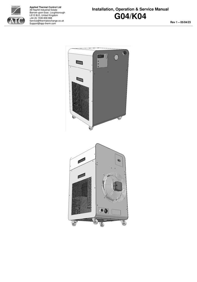
ATC EcoMini EM Series Manual

Applied Thermal Control Ltd
39 Hayhill Industrial Estate
Barrow-upon-Soar, Loughborough
LE12 8LD, United Kingdom
+44 (0) 1530 839 998
Service@thermalexchange.co.uk
Support@app-therm.com
Installation, Operation & Service Manual
EcoMini (EMxxn)
DOCUMENT DETAILS
Date
28/AUG/2020
Author(s)
MJH
Page
1 / 5
Revision
1
Opening section EMPC3 1

Applied Thermal Control Ltd
39 Hayhill Industrial Estate
Barrow-upon-Soar, Loughborough
LE12 8LD, United Kingdom
+44 (0) 1530 839 998
Service@thermalexchange.co.uk
Support@app-therm.com
Installation, Operation & Service Manual
EcoMini (EMxxn)
DOCUMENT DETAILS
Date
28/AUG/2020
Author(s)
MJH
Page
2 / 5
Revision
1
CHANGE LOG
Date
Revision
Page ref
Change
28/AUG/2020
1
All
Pre-manufacture release.
Opening section EMPC3 2

Applied Thermal Control Ltd
39 Hayhill Industrial Estate
Barrow-upon-Soar, Loughborough
LE12 8LD, United Kingdom
+44 (0) 1530 839 998
Service@thermalexchange.co.uk
Support@app-therm.com
Installation, Operation & Service Manual
EcoMini (EMxxn)
DOCUMENT DETAILS
Date
28/AUG/2020
Author(s)
MJH
Page
3 / 5
Revision
1
PRODUCT SPECIFICATIONS
Attribute
Unit
Value
Pending data collection
Power consumption curves
Cooling capacity curves
Pump performance curves
Dimensions (W*D*H)
mm
180*435*380
inch
7.1*17.1*15
Weight
kg
20
lbs.
44.1
Heat transfer fluid volume
mL
650
USGal
0.172
Cooling capacity
(Tambient +20°C / +68°F)
(Tsetpoint +20°C / +68°F)
W
500
BTU/h
1706
RT
0.142
Standard temp. range
°C
+4 to +35
Optional temp. range
°C
-10 to +65
Power supply requirement
VAC
100-240
Hz
50/60
A
1@240VAC
2@115VAC
Sound pressure level
dB
64
Auto-diagnostic functions
Undertemperature cutout
Overcurrent cutout
Refrigeration overpressure cutout
Display
Process temperature
Compressor active/inactive
Fluid fittings (standard)
Pushfit 12mm
Fluid fittings (option)
Valved QR
Tool-less access
No
Undertemperature
protection
Via display setup
Overtemperature
protection
Hardware limited
Compressor overload
protection
Via PCB function
Overcurrent protection
Fused, 2* T6.3A H250V
Rated duty cycle
Continuous
1st party approvals
CE
3rd party approvals
UL61010-1
CAN/CSA-C22.2
FCC CFR47 Part 15 Subpart B
IEC61000-6-4:2007 +A1:2011
IEC61000-6-2:2005
IEC61000-3-2:2014
IEC61000-3-3:2013
Compatible heat transfer
fluids
DI water
Propylene glycol Hexid A4, A6
Opening section EMPC3 3

Applied Thermal Control Ltd
39 Hayhill Industrial Estate
Barrow-upon-Soar, Loughborough
LE12 8LD, United Kingdom
+44 (0) 1530 839 998
Service@thermalexchange.co.uk
Support@app-therm.com
Installation, Operation & Service Manual
EcoMini (EMxxn)
DOCUMENT DETAILS
Date
28/AUG/2020
Author(s)
MJH
Page
4 / 5
Revision
1
SAFETY NOTICES
For your safety, we draw your attention to the following warning and caution marks throughout the manual; the
safe operation of an ATC chiller always remains the responsibility of the operator. This equipment is intended to
be used as a liquid temperature conditioning device –it requires no external pump, nor any further manipulation
of temperature. If the equipment is used in a manner not specified by the manufacturer, the protection provided by
the equipment may be impaired.
Caution; Failure to comply with a caution will invalidate product warranty and absolve ATC from any
liability, howsoever caused, and could result in permanent damage to equipment.
Caution; Filling/topping up of the tank should only be undertaken with the unit switched off, to prevent
back-filling of the fluid.
Caution; The high integrity refrigeration system contains no user-serviceable parts. Repair and service
requires specialized knowledge and tools to be provided by ATC or its local agent. Any unauthorized
tampering with the refrigeration system automatically invalidates warranty.
Warning; Very cold surfaces and gases, lower than -20°C (-40°F). Severe frostbite hazard.
Warning; Opening the refrigeration system may expose the operator to toxic and corrosive compounds
(HFCs). Take protective measures including suitable eye protection.
Warning; Gases may exceed 15 barg (220psig) during operation.
Warning; Refrigerant is class A1. It does not support combustion but is oxygen depleting. Review
equipment rating label for specific refrigerants and CO2e.
Warning; Water and electricity are in close proximity. Always ensure the unit is isolated before service.
The R-series is protected from overcurrent by mains fusing. Never bypass these components.
Warning; Failure to comply with a ‘warning’ may result in personal injury or death. ATC does not accept
any liability for injury caused through use of this equipment.
Warning; After switching off, the fan blades slow to a stop. Do not open until the fan has stopped
rotating.
Affixed to the chiller’s fan, this symbol printed on yellow background advises of the possible damage to
fingers or other extremities from rotating fan blades. Allow blades to stop before service begins.
Opening section EMPC3 4

Applied Thermal Control Ltd
39 Hayhill Industrial Estate
Barrow-upon-Soar, Loughborough
LE12 8LD, United Kingdom
+44 (0) 1530 839 998
Service@thermalexchange.co.uk
Support@app-therm.com
Installation, Operation & Service Manual
EcoMini (EMxxn)
DOCUMENT DETAILS
Date
28/AUG/2020
Author(s)
MJH
Page
5 / 5
Revision
1
INCLUDED ANNEXES
Specific technical product information is provided in the following series of annexes.
Annex A-1 191122 Unpacking - Weighing over 18kg
Annex B-1 191122 Mini site and environmental requirements
Annex C-1 200901 Installation - Mini & EcoMini
Annex D-2 200828 EcoMini fill procedure
Annex E-6 200826 Z31GS Controller & Variable Resistor
Annex F-1 191129 Pres & flow in Mini with centrif pump
Annex G-6 200828 EcoMini, generic initial troubleshooting
Annex H-1 191121 Generic periodic maintenance for end users
Annex I-1 191129 Generic maintenance for technicians
Annex J-1 200901 EcoMini & Mini series EU DoC
Annex J-5 200706 Conflict Minerals compliance statement
Annex J-7 200715 REACH compliance statement
Annex J-8 200827 POPs compliance statement
Annex K-1 200623 Standard warranty terms of ATC
Annex M-1 200828 Recommended spares, Mini & EcoMini
Annex R-1 170621 SDS for refrigerant HFC-R134a
Annex R-3 200203 SDS Hexid A4 v6.3
Opening section EMPC3 5

Applied Thermal Control Ltd
39 Hayhill Industrial Estate
Barrow-upon-Soar, Loughborough
LE12 8LD, United Kingdom
+44 (0) 1530 839 998
Service@thermalexchange.co.uk
Support@app-therm.com
Operating Manual; Unpacking
Annex A-1
DOCUMENT DETAILS
Date
22/NOV/2019
Author(s)
MJH / LW
Page
1 / 1
Revision
1
UNPACKING
Please check that both the packaging and the unit are undamaged. If there is any doubt, it is vital that you inform
both ATC and the carrier. There are no hidden shipping bolts or other fixings. You should inspect the packaging
for signs of transit damage before signing for the unit, and if possible, unpack the unit before signing. Once you
have signed for the goods, ATC cannot be held responsible for any transit damage subsequently found.
As the unit is >18kg, ATC must recommend that 2 persons are used to lift by hand, or a crane. Remove the unit
from its original packaging and ensure that there is no packaging left around the cooling ducts. There is no
internal product packaging that requires the chiller to be opened.
Please retain all packaging in the unlikely event that the chiller needs to be returned to our local
representatives.
Annex A-1 191122 Unpacking - Weighing over 18kg 6

Applied Thermal Control Ltd
39 Hayhill Industrial Estate
Barrow-upon-Soar, Loughborough
LE12 8LD, United Kingdom
+44 (0) 1530 839 998
Service@thermalexchange.co.uk
Support@app-therm.com
Operating Manual; Site & Environmental Requirements
Annex B-1
DOCUMENT DETAILS
Date
November 2019
Compiled by
MJH
Revision
1
SITE & ENVIRONMENTAL REQUIREMENTS
a) Hard, level surface –Feet on the Mini provide a degree of friction on most work surfaces to prevent sliding.
A level surface is important for ensuring proper filling and allowing air to escape.
b) Clean, dust-free environment –air-cooled chillers move large volumes of air, and large amounts of air-
borne contamination will result in fouling of the condenser, reducing the capacity of the unit and in extreme
cases causing a system shut-down.
c) Non-condensing ambient –+5°C to +40°C (+39°F to +104°F). Capacity is lost above +30°C (+86°F).
d) Humidity - 80% for ambient temperatures up to +31°C (+88°F), decreasing linearly to 50% relative humidity
at +40°C (+104°F) ambient temperature.
e) Electrical supply –the Mini comes with a Switch Mode Power Supply capable of accepting;
a. Voltage fluctuations of ±10% of the nominal voltage.
b. Frequency of 47Hz to 63Hz inclusive.
c. Maximum current draw of 5.8A@100VAC; mains fusing is rated 6.3A, accessible from rear.
i. See product rating label for fuse specification.
ii. Two modes of supply are acceptable; L1 / N / E or L1 / L2 / E
iii. The inlet module itself is rated 10A 250V.
iv. Protective earth must be provided by user at IEC type C14 appliance inlet.
f) Clearance –left and right of the unit require clearance of ≥300mm (≥11.8”). Care must be taken to prevent
the recirculation of rejected hot air, back into the condenser. This will result in damage if repeated. Ensure
there is sufficient room at the rear of the product to remove the power cable without obstruction.
g) Plumbing –tubing, piping or hose must be clean and compatible with the fluid to be used. The chiller is
compatible with deionized water and water-glycol mixtures such as Hexid fluid.
h) Indoor use only –altitude up to 2000m.
i) Installation category –transient overvoltage category II; Pollution degree 2. Temporary overvoltages
occurring on mains supply are acceptable within limits defined in the aforementioned categories.
Caution; Always use ATC recommended fluids in your chiller –many other anti-freeze mixtures have the
potential to corrode your application and to damage seals in the chiller.
Annex B-1 191122 Mini & EcoMini site and environmental requirements 7

Applied Thermal Control Ltd
39 Hayhill Industrial Estate
Barrow-upon-Soar, Loughborough
LE12 8LD, United Kingdom
+44 (0) 1530 839 998
Service@thermalexchange.co.uk
Support@app-therm.com
Operating Manual; Installation
Annex C-1
DOCUMENT DETAILS
Date
28/AUG/2020
Author(s)
MJH/AMI
Page
1 / 1
Revision
1
INSTALLATION
Having ensured that your installation meets all site requirements, it is best practice that the fluid lines between
your application and the chiller have the following characteristics;
a) Short in length –this reduces friction-based pressure drop and addition ambient heat load
b) Large diameter bore –at least 8mm (5/16”).
c) Free from 90° bends –to limit the effects of water hammer. If this cannot be avoided, sharp changes of
direction should be minimized so far as possible. Doing this correctly can yield higher pump performance
and extend time between maintenance intervals. It can also reduce electrical energy consumption.
d) Clean –If your installation is to existing pipe work, it is good practice to flush the system with either a
commercially available central heating cleaner or 5% acetic acid solution. The system should be flushed
clean with tap water to remove all traces of cleaner prior to filling the system. Failing this, it is
recommended to use a domestic bleach in solution with tap water, diluted to the point where the bleach
can longer be smelled by a human.
e) Opaque, ideally black –to inhibit light passing through the tube and algae building up. Alternatively, solid
ABS or copper pipe can be used.
Caution; Never use transparent tubing. UV light will pass through, prompting growth of organic
contamination.
The Mini and EcoMini are supplied with quick release fittings by default either of the CPC or push fit variety. The
former of these have built-in valves to prevent loss of fluid when disconnecting but other types may not. The
mating halves of these connectors are available in a variety of fitting types, i.e. barb, quick release, compression.
Sealing guidelines should be followed for each specific type of fitting.
Ensure that the system is correctly connected, with the chiller outlet connected to the application inlet, and
application outlet connected to chiller inlet. Check all joints are tight and leak free.
Where this product is incorporated into other equipment, it is the responsibility of the assembler to ensure safety.
Caution; Do not replace detachable mains cords with inadequately rated cords. Contact ATC for
appropriately rated products.
Preventing Backfilling –In situations where the chiller is situated physically lower than the application being
cooled it is possible that upon stopping the pump the effect of gravity on the process fluid can cause it to leave
the application.
In this scenario, the fluid falls back into the chiller, placing pressure from the water column upon all chiller water
circuit faces. The weakest point in terms of sealing is the tank lid, and this is typically where fluid will escape the
unit, overflowing into the chiller.
For this reason, it’s always a good idea to situate the chiller higher than the application so that when the pump is
turned off, the tank is the highest point in the system and the liquid will flood into the application which should be
sealed.
If this is not possible, a non-return solenoid valve kit can be installed as an optional standard assembly. Please
Annex C-1 200901 Installation - Mini & EcoMini 8

Applied Thermal Control Ltd
39 Hayhill Industrial Estate
Barrow-upon-Soar, Loughborough
LE12 8LD, United Kingdom
+44 (0) 1530 839 998
Service@thermalexchange.co.uk
Support@app-therm.com
Operating Manual; Filling Procedure
Annex D-1
DOCUMENT DETAILS
Date
28/AUG/2020
Author(s)
AMI
Page
1 / 1
Revision
1
ECOMINI FILLING PROCEDURE
The EcoMini chiller has a different fill procedure to ATC’s other products. Please read the entire passage before
starting and familiarize yourself with the process.
a) Check all application valves are open, including solenoid valves and variable position valves.
i) The chiller will require an open water circuit to pump into.
ii) Any obstructions can increase the time, or entirely prevent the bleeding of air from the system.
b) Remove the cap from the tank lid on the top of the chiller.
i) Fill the tank to leave 10-20mm (0.4-0.8”) of air between water line and where the lid seals.
c) Turn your attention to the power inlet rocker switch on the back of the chiller.
i) Immediately after toggling this switch assuming that the power cord is connected and turned on at the
wall the chiller will begin to pump water.
ii) Leave the chiller running until the water line drops to just above the lower outlet port, then turn it off,
this will only take a couple of seconds is the water is able to flow freely and there is air in the system.
Caution; Do not run the pump dry. Do not deadhead the pump.
d) Repeat steps c) i) and d) until the level no longer drops when the pump is run.
e) Start the chiller by once again toggling the mains inlet rocker switch on the back of the chiller.
i) Leave the cap off the tank for >30mins to allow air to escape, or very loosely screwed on to prevent
water splashing out of the tank.
f) Check the application and tubing for signs of leaks whilst the chiller is running.
i) Replace the tank lid fully when satisfied the system is full and bled of air.
Annex D-2 200828 EcoMini fill procedure 9

Applied Thermal Control Ltd
39 Hayhill Industrial Estate
Barrow-upon-Soar, Loughborough
LE12 8LD, United Kingdom
+44 (0) 1530 839 998
Service@thermalexchange.co.uk
Support@app-therm.com
Operating Manual; Controller Operation
Annex E-6
DOCUMENT DETAILS
Date
28/AUG/2020
Author(s)
AMI, MJH
Page
1 / 2
Revision
1
Z31-GS CONTROLLER & VARIABLE RESISTOR
Controller Z31GS is used as a temperature display and low temperature cutout device. It is used in conjunction with
compressor RA282, whose controller PCB accepts a resistor value to control the RPM of the compressor. ATC fit
a variable resistor and a fixed value resistor in series with one another to ensure the correct behavior.
This type of control prevents the compressor running when cooling demand is low and allows the user to
set the duty they wish the unit to perform when load is high.
In contrast, previous products (ATC KTR-series) would have the compressor run continuously onto a low
temperature limiting mechanical valve. Without load, the unit would run at its coldest until load returned, where it
ran at nominal capacity. If load was lower than nominal capacity, the unit would pull down to the low temperature
valve setting.
SETTING MINIMUM TEMPERATURE & CALIBRATION VALUE ON Z31-GS
Navigation
Upon first powering on, the chiller will arrive at this display after a loading
sequence is complete. Process cooling will start automatically on the fridge
and water circuit.
1. The display will show the current water temperature leaving the chiller but
will take some time to stabilize if the unit has been switched off for some
time.
2. The up and down buttons are used for increasing or decreasing the low
temperature cutoff and for programming the controller.
3. The ‘P’button is used for in conjunction with the arrow buttons to change
the low temperature cutoff (single press) or for entering the settings menu
(5s hold).
4. The ‘U’button is used for returning to normal mode when in programming
mode.
Changing low temperature cutoff
1. From the main display press the ‘P’button and release it immediately this
will show ‘SP’on the display and alternate between this and the set low
temperature cutoff.
2. Use the up and down arrows to change the desired temperature cutoff.
3. Once you are happy do not press any buttons and the display will return
to normal operation.
Entering the programming menu
1. From the main display press and hold the ‘P’button for 5 seconds.
2. Use the up and down arrows to scroll through the menu of editable
parameters.
3. Holding the ‘U’button for 5 seconds will exit and return to the main
display
1
2
3
4
Annex E-6 200826 Z31GS Controller & Variable Resistor 10

Applied Thermal Control Ltd
39 Hayhill Industrial Estate
Barrow-upon-Soar, Loughborough
LE12 8LD, United Kingdom
+44 (0) 1530 839 998
Service@thermalexchange.co.uk
Support@app-therm.com
Operating Manual; Controller Operation
Annex E-6
DOCUMENT DETAILS
Date
28/AUG/2020
Author(s)
AMI, MJH
Page
2 / 2
Revision
1
SETTING UNIT DUTY ON SPEED DIAL
1
The speed dial controls the duty of the compressor within the chiller. This directly translates to how hard the
chiller works at cooling. Turning the speed dial to its extent in a counterclockwise direction will cause the
compressor to stop, preventing any cooling effect. Turning it to its extent in a clockwise direction will cause
the compressor to run at maximum speed offering the most cooling.
2
There are dead zones at both ends of the rotation where the compressor cannot work any harder
(clockwise) or will not start (counterclockwise). Setting the dial somewhere in between will vary the speed to
match the load of the heat generating application.
3
Any change in load will require the speed dial to be adjusted to match.
4
Regardless of the position of the speed dial, the low temperature cutoff controller will stop the compressor if
the process water temperature falls below its set value and will not start again until it rises above it.
REMARKS ON COMPRESSOR BEHAVIOR WHEN MAKING ADJUSTMENTS TO SPEED DIAL
5
If the speed dial is set to zero or the controller’s low temperature cutoff stops the compressor automatically,
then the compressor controller will wait 60 seconds before starting back up. This lets pressure equalize to
ensure longevity of the compressor.
6
The compressor will also automatically slowly ramp up or down its speed when the speed control is altered
to allow for proper oil distribution throughout the refrigeration system.
Compressor minimum speed is 20RPS (revolutions per second) and maximum of 100RPS. It takes 1
second per 1RPS for the speed of the compressor to change.
For example; if the speed dial is rotated from its lowest speed to its highest, it will take 80 seconds to arrive
at maximum speed. The same applies in the other direction.
7
The low temperature cutoff controller does not directly alter the speed of the compressor - it simply prevents
the chiller from cooling below a set temperature.
Annex E-6 200826 Z31GS Controller & Variable Resistor 11

Applied Thermal Control Ltd
39 Hayhill Industrial Estate
Barrow-upon-Soar, Loughborough
LE12 8LD, United Kingdom
+44 (0) 1530 839 998
Service@thermalexchange.co.uk
Support@app-therm.com
Operating Manual; Pressure & Flow Adjustment
Annex F-1
DOCUMENT DETAILS
Date
29/NOV/2019
Compiled by
MJH
Revision
1
PRESSURE AND FLOW ADJUSTMENT IN MINI CHILLER WITH CENTRIFUGAL PUMP
The Mini is available with a range of pump options. Low pressure requirements are best served by the quieter and
mechanically looser centrifugal types –the flow of these items is dictated by the backpressure of the pipework
through which it must pump. Reviewing the pump flow curve can indicate the flow expected. Centrifugal pumps
have such a limited maximum pressure, that the water circuit components alone can hold the pressure, and no
pressure relief valve is fitted.
If further limitation of pressure is required, a flow control valve can be fitted to either the outlet or inlet of the
chiller, depending on whether the application is to be pressurized or not.
Annex F-1 191129 Pres & flow in Mini with centrif pump 12

Applied Thermal Control Ltd
39 Hayhill Industrial Estate
Barrow-upon-Soar, Loughborough
LE12 8LD, United Kingdom
+44 (0) 1530 839 998
Service@thermalexchange.co.uk
Support@app-therm.com
Operating Manual; Troubleshooting
Annex G-6
DOCUMENT DETAILS
Date
28/AUG/2020
Author(s)
MJH/AMI
Page
1 / 1
Revision
1
ECOMINI GENERIC INITIAL TROUBLESHOOTING
Symptom
Potential Cause(s)
Compressor not running
Ensure that the minimum temperature cutoff value on the low temperature cutoff
controller is not higher than the current liquid temperature.
Ensure that the speed dial is not positioned within the compressor stop region
which is to its left most extremity.
Check the connection of the compressor power plug situated on top of the
compressor itself.
Check the connection of the signal line from the controller to the compressor
PCB control board.
When the compressor has been running for any length of time and then has
been issued a stop signal either by manually turning the speed control all the
way counter-clockwise of via the low temperature cutoff controller the
compressor will remain stopped for 60 seconds to allow system pressure to
equalize.
The compressor has built-in logic issued via its PCB control board –board error
states are communicated to the main touchscreen controller.
Noisy operation
Usually bearing failure in rotating machinery causes noise –this might be the
cooling fan, the compressor or the pump. Pay attention to specific components
to identify the source of noise.
If there is an air pocket within the water circuit or not enough liquid in the tank,
the pump could be running dry, this can cause rapid degradation of the pump,
top up the tank immediately if the water level is low this will also help to remove
air pockets.
Fluid lines becoming fouled /
containing biological matter
Not using opaque tubing can lead to UV light passing through the tubing,
prompting growth of organisms.
Not following maintenance schedule for cleaning/flushing.
Fluid seen leaking from system
Your fluid may be incompatible with the materials used in chiller construction.
Contact ATC to ensure the fluid is compatible.
Rapid changes in system temperature can cause some materials to change
shape at a faster rate than others. Contact ATC to discuss alternative materials
and parts in water circuit construction.
If there is too much liquid in the system due to backfilling when turned off or air
pockets it is possible that is could have leaked out around the tank cap, check
the water level in the tank periodically to ensure that it is not overflowing.
Poor cooling capacity
(undercooling)
Check for any error states on the compressor controller PCB –the blinking LED
will indicate if an error has occurred and alter blink rate based on error number.
This can be caused by 1) excess application thermal heat load, 2) excess
ambient temperature, 3) fan failure, or 4) controller issues with compressor
control.
Annex G-6 200828 EcoMini, generic initial troubleshooting 13

Applied Thermal Control Ltd
39 Hayhill Industrial Estate
Barrow-upon-Soar, Loughborough
LE12 8LD, United Kingdom
+44 (0) 1530 839 998
Service@thermalexchange.co.uk
Support@app-therm.com
Operating Manual; Maintenance for End-Users
Annex H-1
DOCUMENT DETAILS
Date
November 2019
Compiled by
MJH
Revision
1
PERIODIC MAINTENANCE REQUIREMENTS BY END USER
Caution; Failure to carry out service at the specified intervals may permanently damage your
equipment.
Print this sheet out and display close to the chiller to maximize the visibility of maintenance requirements.
Weekly
Week 1
Week 2
Week 3
Week 4
Check fluid level –top up
as required.
Monthly
J
F
M
A
M
J
J
A
S
O
N
D
Check the condenser is
free from dust or
accumulation of debris.
Annually
Y1
Y2
Y3
Y4
Y5
Y6
Y7
Y8
Drain process fluid and
replace with fresh fluid.
Check for fluid leaks
throughout chiller and
application.
Clear any debris from
inside the chiller.
A vacuum cleaner is recommended for cleaning out the condenser, while soft cloths and IPA are
recommended for cleaning metallic surfaces. If any spillages have occurred, best practice is to allow the water
to evaporate off and wipe up remaining glycol residue with a cloth. Always clean with power supply isolated.
Caution; Never blow out the condenser with compressed air.
Caution; If the mains lead is lost or damaged, contact ATC who will be able to supply a replacement of
the correct specification.
Annex H-1 191121 Generic periodic maintenance for end users 14

Applied Thermal Control Ltd
39 Hayhill Industrial Estate
Barrow-upon-Soar, Loughborough
LE12 8LD, United Kingdom
+44 (0) 1530 839 998
Service@thermalexchange.co.uk
Support@app-therm.com
Operating Manual; Maintenance for Technicians
Annex I-1
DOCUMENT DETAILS
Date
29/NOV/2019
Author(s)
MJH
Page
1 / 1
Revision
1
GENERIC MAINTENANCE FOR TECHNICIANS
Warning; Opening the refrigeration system may expose the operative to toxic and corrosive compounds
(HF). Take protective measures including suitable eye protection.
Warning; Gases may exceed 300 psi (20 bar) during operation.
Warning; All refrigerants do not support combustion and are asphyxiating gases.
Warning; After switching off, the condenser cooling fan blades continue to rotate. Do not attempt
servicing whilst the blades are rotating.
Warning; All chillers contain water and electricity in close proximity. Ensure the unit is isolated before
service. The Mini is protected from overcurrent by fuses on the mains inlet. Never bypass the fuses.
Following service or repair by a trained technician;
a) Ensure any electrical connections that may have been disturbed are given the ‘tug-test’
b) Ensure earth bonding conductors are re-attached.
c) Ensure the correct fuses are in place.
d) Ensure the mains cord being used is to specification, and is free from damage
e) Subject the unit to a PAT test to ensure the unit is safe before running.
f) Ensure there are no leaks inside or outside the unit.
g) Using the wiring schematic for guidance, simulate faults to check each interlock’s function.
Annex I-1 191129 Generic maintenance for technicians 15

Applied Thermal Control Ltd
39 Hayhill Industrial Estate
Barrow-upon-Soar, Loughborough
LE12 8LD, United Kingdom
+44 (0) 1530 839 998
Service@thermalexchange.co.uk
Support@app-therm.com
Operating Manual; Declarations & Approvals
Annex J-1
DOCUMENT DETAILS
Date
6/JAN/2020
Author(s)
MJH
Page
1 / 1
Revision
3
EU DECLARATION OF CONFORMITY
Document layout;
Governed by Machinery Directive 2006/42/EC, Annex II.
REGISTERED BUSINESS ADDRESS
Applied Thermal Control Ltd, 39 Hayhill Industrial Estate, Barrow-upon-Soar, Loughborough, LE12 8LD, UK.
AUTHORISATION TO COMPILE THE TECHNICAL FILE
Mitchell Howard, Applied Thermal Control Ltd, 39 Hayhill Industrial Estate, Barrow-upon-Soar, Loughborough,
LE12 8LD, UK.
DESCRIPTION & IDENTIFICATION OF MACHINERY
Generic denomination;
Mini-Series.
Function;
Recirculating chiller
Model;
All with ‘M’ prefix.
Type;
Air-cooled or water-cooled vapour compression-based.
Serial number;
Commercial name;
As above.
NOTIFIED BODY
Not applicable
QUALITY ASSURANCE SYSTEM
QMS International Ltd, Muspole Court, Muspole Street, Norwich, NR3 1DJ, United Kingdom.
ASCB Registered; 201409-2
DECLARATION
The manufacturer declares that the machinery described above fulfils all the relevant provisions of the;
•Machinery Directive 2006/42/EC.
•EMC Directive 2014/30/EU, via harmonised standards;
oIEC 61000-6-2:2005 (Immunity for industrial environments).
oIEC 61000-6-4:2006 +A1:2011 (Emission for industrial environments).
•Low Voltage Directive 2014/35/EU.
•RoHS Directive 2011/65/EU (RoHS 2);
oThe machinery above contains no Lead (Pb), Mercury (Hg), Cadmium (Cd), Hexavalent Chromium
(Cr6+), Polybrominated Biphenyls (PBB) or Polybrominated Diphenyl Ether (PBDE).
•RoHS Directive (EU) 2015/863 (RoHS 3);
oBis(2-Ethylhexyl) phthalate (DEHP): < 1000 ppm
oBenzyl butyl phthalate (BBP): < 1000 ppm
oDibutyl phthalate (DBP): < 1000 ppm
oDiisobutyl phthalate (DIBP): < 1000 ppm
PERSON EMPOWERED TO DRAW UP DECLARATION
Robert Poniatowski, CEO
Signed in Barrow-upon-Soar, UK, date 6/JAN/2020
Annex J-1 200901 EcoMini & Mini series EU DoC 16

Applied Thermal Control Ltd
39 Hayhill Industrial Estate
Barrow-upon-Soar, Loughborough
LE12 8LD, United Kingdom
+44 (0) 1530 839 998
Service@thermalexchange.co.uk
Support@app-therm.com
Operating Manual; Declarations & Approvals
Annex J-5
DOCUMENT DETAILS
Date
6/JUL/2020
Author(s)
MJH
Page
1 / 1
Revision
1
CONFLICT MINERALS COMPLIANCE STATEMENT
Applied Thermal Control (ATC) adheres to and embraces the ethical values that support our everyday activities.
As an expression of these principles and ethical values, ATC adheres to the principle of responsible sourcing of
components containing precious and non-precious metals and metal salts in compliance with applicable laws and
regulations.
The metals considered are Tantalum (Ta), Tungsten (W), Tin (Sn) and Gold (Au). ATC actively sources
components from suppliers known to be reputable and could demonstrate compliance upon request with the
Conflict Minerals acts and guidelines.
ATC uses Gold and Tin in electrical components, on PCBs and in rotating machinery, as governed by technical
requirements of products. These metals could potentially originate from conflict mineral sites. As many of our
suppliers do not purchase these metals direct from smelters, both they and ATC must rely heavily on information
that will be provided by their suppliers to determine the source and chain of the metals in those products.
ATC is committed to working with its customers and supply chain to meet the customer’s specification and
requirements with regards to traceability, sourcing requirements and restrictions. ATC commits that, to the best of
our knowledge, our suppliers are complying with the conflict minerals act as stated in their documentation. These
statements are reviewed, and updates obtained as required.
Mitchell Howard, Technical Manager
Signed in Coalville, UK, date 6/JUL/2020
Annex J-5 200706 Conflict Minerals compliance statement 17

Applied Thermal Control Ltd
39 Hayhill Industrial Estate
Barrow-upon-Soar, Loughborough
LE12 8LD, United Kingdom
+44 (0) 1530 839 998
Service@thermalexchange.co.uk
Support@app-therm.com
Operating Manual; Declarations & Approvals
Annex J-7
DOCUMENT DETAILS
Date
15/JUL/2020
Author(s)
MJH
Page
1 / 1
Revision
1
WHAT IS THE REACH REGULATION 1907/2006?
REACH is a regulation of the European Union, adopted to improve the protection of human health and the
environment from the risks that can be posed by chemicals, while enhancing the competitiveness of the EU
chemicals industry. REACH places the burden of proof on companies. To comply with the regulation, companies
must identify and manage the risks linked to the substances they manufacture and market in the EU. They have
to demonstrate to ECHA how the substance can be safely used, and they must communicate the risk
management measures to the users. If the risks cannot be managed, authorities can restrict the use of
substances in different ways. In the long run, the most hazardous substances should be substituted with less
dangerous ones. REACH stands for Registration, Evaluation, Authorization and Restriction of Chemicals. It
entered into force on 1/JUN/2007.
REACH ‘ARTICLE’COMPLIANCE CONSIDERATIONS
REACH ANNEX XVII COMPLIANCE
Substances under Annex XVII are restricted either in full (not to be used at all) or for specific uses (can be used in
some uses but cannot be used in identified uses).
Applied Thermal Control has contacted all our suppliers and to the best of our knowledge, none of the articles that
we sell intentionally contain any of the Annex XVII substances currently on the candidate list in concentrations of
>0.1% by weight.
REACH ANNEX XIV COMPLIANCE
Substances under Annex XIV require authorization to use in the EU after sunset date, require communication to
downstream recipients when over threshold (0.1% w/w at article level) and require notification to ECHA when
SVHC over threshold and imported over 1000kg annually and use not already registered.
Applied Thermal Control has contacted all our suppliers and to the best of our knowledge, none of the articles that
we sell intentionally contain any of the Annex XVII substances currently on the candidate list in concentrations of
>0.1% by weight.
SVHC LIST COMPLIANCE
Substances of Very High Concern (SVHC) require communication to downstream recipients when over threshold
(0.1% w/w at the article level), notification to the European Chemicals Agency (ECHA) when SVHC over
threshold and when imported over 1000kg annually and use not already registered.
Applied Thermal Control has contacted all our suppliers and to the best of our knowledge, none of the articles that
we sell intentionally contain any of the Annex XVII substances currently on the candidate list in concentrations of
>0.1% by weight.
DECLARATION
Mitchell Howard, Technical Manager
Signed in Barrow-upon-Soar, UK, date 15/JUL/2020
Annex J-7 200715 REACH compliance statement 18

Applied Thermal Control Ltd
39 Hayhill Industrial Estate
Barrow-upon-Soar, Loughborough
LE12 8LD, United Kingdom
+44 (0) 1530 839 998
Service@thermalexchange.co.uk
Support@app-therm.com
Operating Manual; Declarations & Approvals
Annex J-8
DOCUMENT DETAILS
Date
27/AUG/2020
Author(s)
MJH
Page
1 / 1
Revision
1
WHAT IS THE POPs REGULATION 2019/1021?
POPs stands for persistent organic pollutants. In Europe, the global Stockholm Convention is implemented
through POPs legislation. POPs are organic substances that persist in the environment, accumulate in living
organisms and pose a risk to our health and the environment. They can be transported by air, water or migratory
species across international borders, reaching regions where they have never been produced or used.
International risk management is necessary as no region can manage the risks posed by these substances alone.
The European Parliament (and Council) issued regulation 2019/1021 on 20/JUN/2019, and further amended
(regulation 2020/784) on 8/APR/2020.
POPs LISTED UNDER INITIAL REGULATION 2019/1021
Pesticides;
Aldrin, Chlordane, DDT, Dieldrin, Endrin, Heptachlor, Hexachlorobenzene, Mirex, Toxaphene.
Industrial Chemicals;
Hexachlorobenzene, Polychlorinated Biphenyls (PCBs).
Industrial Chemical Byproducts;
Hexachlorobenzene byproducts;
Polychlorinated dibenzo-p-dioxins and polychlorinated dibenzofurans (PCDD/PCDF), and PCBs.
POPs LISTED UNDER AMENDMENT 2020/784
Perfluorooctanoic acid (PFOA), its salts and PFOA-related compounds.
POPs COMPLIANCE STATEMENT
We certify that to the best of our knowledge, based upon up-to-date information from our suppliers, all products
supplied by Applied Thermal Control are fully POPs compliant in accordance with regulations and amendments
above mentioned.
DECLARATION
Mitchell Howard, Technical Manager
Signed in Barrow-upon-Soar, UK, date 27/AUG/2020
Annex J-8 200827 POPs compliance statement 19

Applied Thermal Control Ltd
39 Hayhill Industrial Estate
Barrow-upon-Soar, Loughborough
LE12 8LD, United Kingdom
+44 (0) 1530 839 998
Service@thermalexchange.co.uk
Support@app-therm.com
Operating Manual; Warranty Terms
Annex K-1
DOCUMENT DETAILS
Date
23/JUN/2020
Author(s)
RW, MJH
Page
1 / 1
Revision
2
WARRANTY TERMS
Please visit the website warranty registration page to ensure ATC can offer you the best possible support;
https://www.app-therm.com/warranty-registration/
a) For how long is my ATC product warrantied?
ATC provides a comprehensive return to base 2-year parts, 1-year labor warranty from delivery as
standard on all new equipment, provided it has been installed and operated in accordance with the
manual.
b) Where will ATC fulfill the product warranty?
ATC’s standard warranty terms are Return to Base (RTB) – issues with chillers are often easily solvable
over the phone or email, or by reviewing ATC’s technical guidance on the web and in the product manual.
On occasion, at the discretion of ATC, goods may be serviced on site FOC or a service loan unit may be
supplied. Warranty cover excludes the cost of travel by engineers and loan unit rental charges. Obtaining
onsite service for a product, even in full warranty, is a chargeable service.
c) Who is liable for shipping charges in the event of warranty failure?
During the first year of the warranty period, freight costs for shipping to ATC are for the customer’s
account. Freight costs for shipping from ATC are for ATC’s account.
During the second year of the warranty, freight costs to and from ATC are for the customer’s account.
d) I’m experiencing problems with my chiller. It’s within warranty –what do I do next?
Contact ATC to discuss the issue you are having. The contact details in the header of this document are
an ideal place to start. Be sure to have your model number and serial number on-hand to aid those
attempting to solve remotely.
e) Telephone support couldn’t fix my chiller – what do I do next?
An RMA form must be completed. This allows both the end-user and ATC to clarify your details, to set the
party responsible for shipping costs, and to set a different return address if desired. Shipping advice is
provided, and the end-user must sign a declaration that states the unit is safe to handle. Return the form
by email for fastest response.
f) What happens if my chiller failed outside warranty or requires non-warranty repair work?
A purchase order will be requested to cover an initial inspection –this will only be invoiced if the inspection
shows there is no fault. If packaging is required, i.e. a crate, a separate charge will be levied. If the end
user prefers ATC to arrange a collection, a shipping charge may be levied.
g) Our process must continue running –can we have a loan unit whilst our chiller is in repair?
ATC hold several standard air-cooled chillers at the factory for the sole purpose of offering for loan –these
are available on a first-come, first-serve basis. Models up-to 3kW capacity are available.
Annex K-1 200623 Standard warranty terms of ATC 20
This manual suits for next models
1
Table of contents
Other ATC Chiller manuals
Popular Chiller manuals by other brands

Trane
Trane 4YCZ5036F1070B Installation and operation manual

Husky
Husky C Series user manual

Johnson Controls
Johnson Controls YORK Tempo YLAA Series Installation operation & maintenance

Trane
Trane Airfinity XL IH Installation operation & maintenance

SP Scientific
SP Scientific ULTRA-COOL Operator's manual

Baltimore Aircoil Company
Baltimore Aircoil Company ICE CHILLER TSU-M Series Operating and maintenance instructions