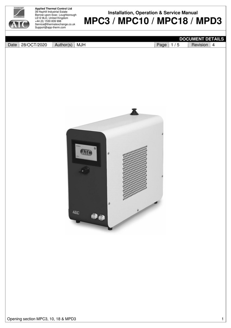
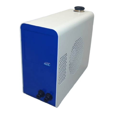
ATC Mergen M4512V User manual

EN_User Guide Mergen V0.2 samet , Mergen
1
Think different, be different!
User Guide
Mergen
USER MANUAL
CORRIGO
ENGLISH

EN_User Guide Mergen V0.2 samet, Mergen
2
Think different, be different!
CONTENTS
CONTENTS ............................................................................................................................................... 2
INTRODUCTION ....................................................................................................................................... 4
MANUFACTURER ..................................................................................................................................... 5
GUARANTEE ............................................................................................................................................ 5
GENERAL TECHNICAL DESCRIPTION ........................................................................................................ 6
AHU SERIES ......................................................................................................................................... 6
CASING ................................................................................................................................................ 6
FILTERS ................................................................................................................................................ 6
HEAT EXCHANGER .............................................................................................................................. 6
FANS AND MOTORS ........................................................................................................................... 7
DUCT CONNECTIONS .......................................................................................................................... 7
DELIVERY CONFIGURATION AND BASIC FRAME ............................................................................... 7
POSSIBLE OPTIONS ............................................................................................................................. 7
TECHNICAL TABLES ............................................................................................................................. 7
DIMENSIONS ....................................................................................................................................... 8
REQUIRED SPACES .............................................................................................................................. 9
ELECTRICAL SUPPLY .......................................................................................................................... 10
MONOPHASE – TRIPHASE CHANGE (ONLY FOR M4512-M4516) .................................................... 10
POSITIONING OF THE COMPONENTS .............................................................................................. 11
DESCRIPTION OF THE MODEL .......................................................................................................... 12
MAINTENANCE ...................................................................................................................................... 13
BEFORE YOU START THE MAINTENANCE ........................................................................................ 13
ATTENTION DURING MAINTENANCE............................................................................................... 13
REGULAR MAINTENANCE ................................................................................................................. 13
Fan: ............................................................................................................................................... 13
Changer: ........................................................................................................................................ 14
Filter: ............................................................................................................................................. 14
Coil: ............................................................................................................................................... 14
Drainage: ....................................................................................................................................... 14
Housing: ........................................................................................................................................ 15
TROUBLESHOOTING .............................................................................................................................. 15

EN_User Guide Mergen V0.2 samet, Mergen
3
Think different, be different!
DISPLAY, KEYS AND LEDS ...................................................................................................................... 17
DISPLAY ............................................................................................................................................. 17
KEYS AND LEDS ................................................................................................................................. 17
ACCESS RIGHTS ..................................................................................................................................... 18
SIGN UP ............................................................................................................................................. 18
SIGN OFF ........................................................................................................................................... 19
CHANGE PASSWORD ........................................................................................................................ 19
LANGUAGE ............................................................................................................................................ 19
VERSION NUMBER ................................................................................................................................ 19
THE MENU SYSTEM ............................................................................................................................... 20
NAVIGATE THROUGH THE MENUS .................................................................................................. 20
CHANGE PARAMETERS ..................................................................................................................... 21
COMPANY MODE .................................................................................................................................. 22
OPERATING MODE UNIT .................................................................................................................. 22
ALARM EVENTS ................................................................................................................................. 22
IN/OUT ACCESSES ............................................................................................................................. 22
Analogue inputs: ........................................................................................................................... 22
Digital Inputs: ................................................................................................................................ 22
TEMPERATURE ...................................................................................................................................... 23
SET POINT VALUE FOR TEMPERATURE CONTROL OF SUPPLY AIR .................................................. 23
SET POINT VALUE WEATHER-DEPENDENT SUPPLY AIR CONTROL ................................................. 23
DEFROSTING EXCHANGER ................................................................................................................ 23
AIR CONTROL ........................................................................................................................................ 24
TIME SETTINGS ...................................................................................................................................... 25
GENERAL ........................................................................................................................................... 25
TIME/DATE ....................................................................................................................................... 25
TIMER FULL SPEED ............................................................................................................................ 25
ALARM HANDLING ................................................................................................................................ 26
ALARM LIST ....................................................................................................................................... 27
INDICATORS .......................................................................................................................................... 29
STATUS INDICATION ......................................................................................................................... 29
ANNEX ................................................................................................................................................... 30
OVERVIEW OF MENU CONTROLLER ................................................................................................ 30
NOTES.................................................................................................................................................... 31
EN_User Guide Mergen V0.2 samet, Mergen
4
Think different, be different!
INTRODUCTION
This user manual contains important information on the correct and
safe use of the MERGEN appliance. Therefore, please read the user
manual completely before using the device. Otherwise, there may be
danger to persons and damage to the device.
The unit has a rating plate on the front. The rating plate contains the
serial number and the required markings for identifying the unit.
The controller manual is valid for all ATC MERGEN (M45xx) models equipped with an integrated
controller.
Control
mode
Type
Description
Mode 1
Standard regulation
Automatic temperature control of supply air with
external compensation, % low flow - % high flow -
time based LS / HS speed switching
Mode 2
CO2
control
Automatic temperature control with external
compensation, % low flow -% high flow - CO2
concentration based LS/HS speed switching
Mode 3
Constant pressure control
(Automatic temperature control of supply air with
external compensation, % low flow -% high flow -
Pulse channel pressure based LS/HS speed switching
Mode 4
Constant Flow Control
Automatic temperature control of supply air with
external compensation, constant low flow rate in
m³/h - constant high flow rate in m³/h - time-based
LS / HS speed switching
Mode 5
Constant Flow CO2 control
(Automatic temperature control of supply air with
external compensation, constant low flow rate in
m³/h - constant high flow rate in m³/h - CO2
concentration based LS/HS speed switching.
The manual describes only the functions available to users with Operator access rights or below. The
manual is based on the standard (English) menu of the controller.

EN_User Guide Mergen V0.2 samet, Mergen
5
Think different, be different!
MANUFACTURER
ATC Air Trade Centre A.Ş.
Headquarters:
İbrahim Karaoğlanoğlu Caddesi No: 101
34418 Seyrantepe / Istanbul, TURKEY
Factory:
OSB 14. Cad. No:15
35875, Pancar / Torbalı / Izmir, TURKEY
GUARANTEE
The warranty period starts from the date of delivery of the product and is standard 2 (two)
years for MERGEN devices.
All parts of the product manufactured by ATC Air Trade Centre are covered by our
company's warranty.
In case of failure of the product within the warranty period, the time spent on the repair will
be added to the original warranty period. The Product's repair period will not exceed 30
working days. This period starts from the date of notification of the product defect.
During the warranty period of the product, defects in the product due to defects in material,
workmanship and factory assembly will be corrected free of charge.
Faults that result from using the product contrary to what is stated in the operating
instructions and faults that are due to the user's fault are not covered by the guarantee.
Accessories and devices used on our products that are not manufactured by our company
are not covered by our company's warranty.
The warranty is not valid in the case of repairs and modifications made without ATC Air
Trade Centre's written consent and if the unit is not used as specified in the contract with
ATC Air Trade Centre. Damage caused by negligence, lack of maintenance or failure to follow
ATC Air Trade Centre's recommendations is not covered by the warranty.

EN_User Guide Mergen V0.2 samet, Mergen
6
Think different, be different!
GENERAL TECHNICAL DESCRIPTION
AHU SERIES
MERGEN is designed taking into account the requirements for silent air handling units with highly
efficient heat recovery for heating and cooling. The units are sustainably designed with maximum
consideration for the environment. Each component used in MERGEN heat recovery units is selected
with regard to the energy saving principle. All air handling units are supplied pre-wired with
operationally tested control equipment.
MERGEN is a range of compact air handling units with many options, consisting of various complete
functional components and modules in standard lengths. The modules are equipped with selected air
handling functions tailored to the specific requirements.
The MERGEN range consists of 5 different sizes in 5 different control options. The flow rate range is
from 1200 to 5500 m³/h. Each unit has as standard two programmable flow rates that can be selected
at the time of commissioning.
CASING
Thermally broken aluminium profiles with polyamide spacers between the profiles provide a TB2 class
according to EN 1886. Glass fibre corners reinforced with polyamide. Insulation between the double-
skin panels is 45 mm (70 kg/m³) of rock wool, resulting in a T2 class. The exterior panels are lacquered
RAL 7047.
The MERGEN casing achieves class D1, L1, T2, TB2 according to EN1886.
There is a separate technical compartment containing the electrical components and controls. The
electrical components are accessible via a lockable hinged door which houses the IP65 control panel
with LCD display and the isolating switch.
Access to the other internal components, such as the stainless steel condensate drain pan, automatic
bypass, filters or the heat exchanger, is via the removable safety interlock panels.
FILTERS
MERGEN units have as standard a high efficiency F7 filter for fresh supply air and an M5 panel filter
for return air. The filters are always mounted upstream of components to protect them. Mounted on
guides for easy maintenance, fitted with lip seals to ensure effective air tightness.
HEAT EXCHANGER
The units are equipped with Eurovent certified hexagonal aluminium plate exchangers. The exchanger
has an efficiency higher than 80% according to EN308. The bypass with automatic defrosting function
ensures the heating of the fresh air when needed. If the unit has an electric preheating system, the
control will automatically choose the most optimal solution.

EN_User Guide Mergen V0.2 samet, Mergen
7
Think different, be different!
FANS AND MOTORS
MERGEN units are equipped with directly driven plug fans with EC motor, direct current motors with
electronic modulation (EC), high efficiency, thermal protection and integrated speed control. The EC
technology guarantees low consumption by controlling its operating point between 10 and 100%. EC
motors provide a low noise level which results in better acoustic comfort.
DUCT CONNECTIONS
Units with round duct connections have connections with rubber seals.
Units with rectangular duct connections are intended for connection with guide strips. Rectangular
duct connections must be supplemented with a sealing strip.
DELIVERY CONFIGURATION AND BASIC FRAME
MERGEN units can be supplied as: block sections with a foot or block sections with a lifting
eye(without foot).
The frame consists of profiles with feet and carrying slots for transport, with a standard height of
100 mm.
POSSIBLE OPTIONS
Electric preheater
Water or Electric heating coil
External Water or DX Coil
5 different automatic control options
Roof for outdoor use
Hoods for suction and discharge
Motorised stop valve for suction and discharge
Base frame for floor mounting or lifting eye for ceiling mounting
TECHNICAL TABLES
Model
Nominal
Airflow
(m³/h)
Maximum Air
Flow Rate
(m³/h)***
Supply
Voltage (V)
Max Power
Consumption
(kW)**
Max Current
(A)**
M4512 H 1200 1950 400* 1,1 4,78
M4516 H 1600 2450 400* 1,6 6,96
M4523 H 2300 3450 400 2,2 3,34
M4540 H 4000 5150 400 3,7 5,62
M4555 H 5500 7100 400 5,46 8,3
* These units can also be operated with 230V monophase.
** Without accessories.
*** @0 pa external static pressure

EN_User Guide Mergen V0.2 samet, Mergen
8
Think different, be different!
Model Nominal
Airflow (m³/h)
Maximum Air
Flow Rate
(m³/h)***
Supply
Voltage (V)
Max Power
Consumption
(kW)**
Max Current (A)**
M4512 V 1200 1950 400* 1,1 4,78
M4516 V 1600 2450 400* 1,6 6,96
M4523 V 2300 3450 400 2,2 3,34
M4540 V 4000 5150 400 3,7 5,62
M4555 V 5500 7100 400 5,46 8,3
* These units can also be operated with 230V monophase.
** Without accessories.
*** @0 pa external static pressure
DIMENSIONS
Model V L1 B1 H1 H2
Connections
Flange
Round
M4512V
2190
600
1230
1375
490x470
315
M4516V
2250
600
1230
1375
490x470
400
M4523V
2395
730
1430
1575
605x640
450
M4540V
2980
1050
1630
1775
670x540
630
M4555V
3240
1134
1750
1895
1124x730
630
All
d
imensions
are
in
mm.

EN_User Guide Mergen V0.2 samet, Mergen
9
Think different, be different!
Model H L1 B1 H1 H2
Connections
Flange
Round
M4512H
2190
1230
600
700
460x490
315
M4516H
2250
1230
600
700
460x490
400
M4523H
2395
1430
730
830
560x620
450
M4540H
2980
1630
1050
1150
680x940
630
M4555H
3240
1750
1334
1434
730x1225
630
All
d
imensions
are
in
mm.
REQUIRED SPACES

EN_User Guide Mergen V0.2 samet, Mergen
10
Think different, be different!
ELECTRICAL SUPPLY
MONOPHASE – TRIPHASE CHANGE (ONLY FOR M4512-M4516)
All units were produced with tri-phase supply connections in factory. In some projects, it must be
operated with monophase supply. In this situation unit electrical connections can be like below.
For triphase-monophase translation, all connection changings must be made on electrical supply side
of circuit breaker. DO NOT CHANGE ANYTHING ON UNIT SIDE!
The monophase option is not suitable for units which produced with electrical heaters and
M4523/M4540/M455 models!
Cable Cross Sections
Model
Default Unit Unit+PH & Unit+EH Unit+PH+EH
Max
Current
(A)
Cable Details
(mm²)
Max
Current
(A)
Cable Details
(mm²)
Max
Current (A)
Cable Details
(mm²)
M4512 H/V
5,1 5x2,5 9,9 5x2,5 17,1 5x2,5
M4516 H/V
7,1 5x2,5 13,8 5x2,5 23,8 5x4
M4523 H/V
3,7 5x2,5 16,5 5x2,5 29,3 5x4
M4540 H/V
6,1 5x2,5 31,7 5x4 57,4 5x10
M4555 H/V
8,7
5x2,5
42,9
5x6
77,1
5x1
6
C
a
ble
s
ection calculations are base
d on max
50
m cable
length
and
%10 drop
of supply voltage.
P
lease
contact with ATC for different installations!

EN_User Guide Mergen V0.2 samet, Mergen
11
Think different, be different!
POSITIONING OF THE COMPONENTS
Configuration H: Horizontal installation
Configuration V: Vertical installation
No.
Component
1
Supply fan
2
Coil
(electric or water)
3
Bypass valve
4
Exhaust fan
5
Temperature sensor
6
Filter
7
Pressure measurement
8
Plate
Heat
Exchanger
9
Control section
10
Filter outlet

Think different, be different!
DESCRIPTION OF THE MODEL
M45
12
HL
PH
EH
CCW
Mode1
R
D
A
CR
B
MERGEN thermally broken
profile 45mm
B = 100mm Base frame for floor mounting
L = Lifting eye for ceiling installation
12 = 1200 m³/h
16 = 1600 m³/h
23 = 2300 m³/h
40 = 4000 m³/h
55 = 5500 m³/h
CR = Round connection for all sides
CRF = Round connection fresh air
CRS = Round connection supply air
CRR = Round connection return air
CRE = Round connection exhaust air
HL =
H
orizontal
L
eft
HR = Horizontal Right
VL = Vertical Left
VR = Vertical Right
CO = Rectangular connection for all sides
COF = Rectangular connection fresh air
COS = Rectangular connection supply air
COR = Rectangular connection return air
COE = Rectangular connection exhaust air
PH = Electric pre
-
heater
EH = Electric
al
heat
er
HC = Hot water coil
Damper actuator
CCW = Cold water
coil
CCDX = DX coil
Damper
for
both side
Mode 1
Mode 2
Mode 3
Mode 4
Mode 5
R = Roof
RH = Roof and hoods

EN_User Guide Mergen V0.2 samet , Mergen
13
Think different, be different!
MAINTENANCE
The installation and service operations of the unit must be only carried out by authorized technicians!
BEFORE YOU START THE MAINTENANCE
The device must be stopped and the mains voltage switched off.
A wait should be made for the fans to come to a complete stop. A hand or other object should not be
used as a brake to stop the fans.
Make sure the unit is not operated during maintenance, so turn off safety switches such as the
maintenance switch and fuses.
ATTENTION DURING MAINTENANCE
Fans, filters and exchangers must not be cleaned with water under pressure.
Maintenance is not recommended while the aircraft is airborne. If possible, the aircraft should be
taken down and maintained in this manner.
Protective gloves and safety goggles should be used during maintenance.
Maintenance may only be carried out by a competent person.
During maintenance, avoid situations that would upset the balance of the fans and damage the fans.
During maintenance, situations that may damage the structure of filters and exchangers must be
avoided.
REGULAR MAINTENANCE
Periodic maintenance should be performed step by step in the sections of the MERGEN unit.
Fan:
Check for mechanical friction noises: If a mechanical friction noise is heard, the fan should
be stopped. The fan should be replaced with a new one.
Balance check: If it is observed that the fan is not balanced, the fan must be stopped. The
fan should be replaced with a new one.
Fan blades check: The fan must be stopped in case of warping and crushing in the fan
blades. The fan must be replaced with a new one.
Check the fan mounting bolts: The fan mounting bolts should be checked one by one, if
there is a loose bolt, it should be tightened to the correct torque.
Dust, dirt and corrosion control in fans: If the fans become dirty, they should be cleaned
with compressed air or wiped with a damp cloth.
Checking the fan pressure sensor hoses: If a pressure sensor is used for fan speed control,
check that the hoses are still in place. If not, they must be reinserted and damaged hoses
replaced.

EN_User Guide Mergen V0.2 samet, Mergen
14
Think different, be different!
Electrical data check of the motor integrated in the fan: Measure current, voltage, etc. If
the electrical values are lower or higher than they should be, stop the fan and check the
electrical lines.
The above checks must be carried out every 3 months and the ATC after-sales service must be
contacted in the event of a discrepancy.
Changer:
Damage control on aluminum fins: The situations such as crushing and cracks in the
aluminum fins that make up the heat exchanger will reduce the efficiency of the MERGEN
device, so if this situation occurs, the exchanger must be replaced.
Cleaning of aluminium fins: The aluminium fins of the heat exchanger must be cleaned of
dust and other dirt. Cleaning of the heat exchanger should be done in the summer. The heat
exchanger should be removed from the unit and wiped with a damp cloth, then replaced. No
chemical substances should be used when cleaning the heat exchanger.
Checking the bypass valve blades: The blades of the bypass valve in the heat exchanger
section should be checked. If there are damages, such as bending of the blades, the valve
must be replaced. In addition, the dirt on the surface of the valve must be cleaned.
Checking the tightness of the heat exchanger: To ensure the tightness of the heat
exchanger, the connected gaskets must be checked, the shifted gaskets must be replaced
and the unusable ones must be replaced.
The above checks must be carried out every 3 months and the ATC after-sales service must be
contacted in the event of a discrepancy.
Filter:
Filter checking: The cleanliness of the filters must be checked and the filters must be
cleaned if they are dirty.
Filter tightness check: To ensure the tightness of the filter, the connected gaskets must be
checked, shifted gaskets must be replaced and those that are unusable must be replaced.
Filter pressure switch hose check: Pressure switches are used for the contamination
information of the filters, it should be checked that the hoses of these pressure switches are
in place. If not, they should be reinserted and damaged hoses replaced.
The above checks must be carried out once a month and ATC after-sales service must be contacted
in the event of a discrepancy. Even if monthly periodic maintenance is performed, the filters must be
replaced by new ones once a year.
Coil:
Checking the coil section: The general cleanliness of the water coil, DX coil and electric
heater being used should be checked and cleaned. Foreign objects that obstruct air flow on
the surface of the coils should be cleaned.
The above checks must be carried out every 3 months and the ATC after-sales service must be
contacted in the event of a discrepancy.
Drainage:
Checking the siphon and the condensation trap: The dirt in the condensation trap must be
cleaned. In addition, the water from the siphon must be drained and cleaned.

EN_User Guide Mergen V0.2 samet, Mergen
15
Think different, be different!
The above checks must be carried out every 6 months and the ATC after-sales service must be
contacted in the event of a discrepancy.
Housing:
Checking the casing: The interior and exterior of the unit should be checked for dust, dirt
and corrosion, and dirt should be cleaned with a damp cloth. The parts that begin to form
corrosion should be replaced.
Service door latch and fasteners check: The operation of the door handle, hinge and other
fasteners on the unit should be checked and defective ones replaced.
The above checks must be carried out every 6 months and the ATC after-sales service must be
contacted in the event of a discrepancy.
TROUBLESHOOTING
Problem
Possible reason
Solution
The device does not work
Not
started from the control
panel
The device must be started
from the panel
Alarm in the unit
The cause of the alarm must
be resolved and the alarm
must be reset from the control
panel
Fuse is off
Turn on the fuses and other
switches
Device vibrates Unbalanced fan
The fans must be balanced or
replaced with a new one.
Loose parts in the fan section
Tighten loose parts
The device is excessively noisy
Damaged fan blades
Fan must be replaced
Mechanical friction in the fan
Fan must be
replaced
There is a foreign object in the
device
The housing of the unit must
be checked and cleaned
Unbalanced fan
The fans must be balanced or
replaced with a new one.
Seals (gasket etc.) have shifted
The tightness of the connected
elements must be checked,
the displaced items must be
repaired and the unusable
ones must be replaced.
Structural damage in the fan
There is a foreign object in the
fan of the unit Fan must be replaced
Unbalanced fan
The fans must be balanced or
replaced with a new one.
Unbalanced fan
The fans must be balanced or
replaced with a new one.
Structural damage in the
exchanger
A foreign object hit the heat
exchanger
Heat exchanger must be
replaced
There is ice on the heat
exchanger
The sensor that
protects the
heat exchanger from freezing
must be replaced

EN_User Guide Mergen V0.2 samet, Mergen
16
Think different, be different!
Problem
Possible reason
Solution
The bypass valve is not
working.
Mechanical defect of the valve
The bypass valve must be
replaced.
Failure of the bypass valve
motor Valve motor must be replaced
Water leaks from the
appliance
The siphon's clogged.
The siphon must be
disassembled and cleaned
Congestion drain blockage
The condensate drip tray must
be cleaned and the drainpipe
must be opened.
Insufficient airflow
Incorrect assembly
Adjust the assembly according
to the user manual
Filters are clogged or dirty
Filters must be cleaned or
replaced
Dirty suction and discharge
Suction and discharge must be
cleared
The heat exchanger is clogged
or dirty
Heat
exchanger must be
cleaned or replaced
Fan pressure sensor hoses
relocated
The sensor hoses should be
put back in place
Fault in the fan pressure
sensor
Fan pressure sensor must be
replaced
Too much airflow
The device is open
Close
industrial doors and
possible open spaces
Leaks in the channels
Leaks in the ducts must be
plugged
Fan pressure sensor hoses
relocated
The sensor hoses should be
put back in place
Fault in the fan pressure
sensor
Fan pressure sensor must be
replaced
Continuous measurement of
electrical values at maximum
power
Device operating outside the
theoretical curve
The assembly and other
systems shall be checked and
the device adjusted to normal
operating conditions
Incorrect project
planning for
the electrical wiring
The electrical conduit needs to
be revised.
The wrong choice of capacity
Capacity selects should be
checked

EN_User Guide Mergen V0.2 samet, Mergen
17
Think different, be different!
DISPLAY, KEYS AND LEDS
DISPLAY
The display has 4 lines with 20 character positions each. The display is backlit. The backlight is off,
but is activated when the user presses a key. After a certain period of time with no key presses, the
backlight switches off automatically.
KEYS AND LEDS
UP ARROW
:
Go to previous line in menu.
(Increase parameter value)
ALARM:
Press to view alarm summary.
DOWN ARROW:
Go to the next line in the menu.
(Decrease parameter value)
DELETE:
Resets/cancels change of a parameter
unless OK is already pressed.
ARROW TO THE RIGHT:
Go to lower level in menu.
(Move cursor to the right
within the parameter)
ALARM LED:
Red LED flashes if the alarm has not
yet been acknowledged. After
acknowledgement, the LED remains
lit until the alarm is reset.
LEFT ARROW:
Go to a higher level in the
menu. (Move cursor to the left
within the parameter)
SCREAMING LED:
Some menus have adjustable values.
This is indicated by a flashing yellow
LED. The value can be changed by
pressing OK.
OK:
Open/enable menu/setting
after selection. (Confirm a
parameter value)

EN_User Guide Mergen V0.2 samet, Mergen
18
Think different, be different!
ACCESS RIGHTS
There are four levels of access rights. Normal has the least access rights which do not require logging
in. This is followed by Operator, Service and Admin levels, where Admin has the most rights. The
choice of an access level determines which menus are displayed and also which settings you can
change in those menus.
The basic level only allows you to change the operating mode and gives you read access to a limited
number of menus.
The Operator level gives access to all menus except Configuration.
The Service level provides access to all menus except the Inputs, Outputs and System submenus of
the Configuration menu.
The Admin level gives full read/write rights for all settings in all menus.
In the user manual we only discuss the Normal and Operator menus. To make changes to the other
menus, contact your installer.
In the startup display, press ARROW repeatedly.
DOWN to the marker arrow at the line
Access rights state. Press the RIGHT ARROW.
SIGN UP
This menu allows you to log in at any access level by entering the appropriate 4-digit code. The login
menu also appears if you are trying to access a menu or function that requires higher access rights
than you currently have.
Press OK. A cursor mark will then appear at the first digit position. Press UP ARROW repeatedly until
the correct digit appears. Press RIGHT ARROW to move to the next position. Repeat until all four
digits of the code are displayed. Then press OK to confirm. Shortly afterwards, the new logon level
will be displayed in the Current level line. Press LEFT ARROW to exit the menu.
Factory preset passwords:
Operator: 3333

EN_User Guide Mergen V0.2 samet, Mergen
19
Think different, be different!
SIGN OFF
Use this menu to log out of the current level and go to the
basic 'without logging in' level.
AUTOMATIC UNSUBSCRIBE
At the Operator access level, after a certain period of inactivity, the user is automatically logged off
and the Normal level is activated. That period can be set.
CHANGE PASSWORD
You can only change the password of access levels lower
than the currently active access level.
LANGUAGE
Pressing the RIGHT ARROW three times from the Home menu displays a menu where you can select
a different display language.
The language files are stored in the application memory and are copied to the working memory. If you
have loaded a newer program version than the manufacturer's revision via Application tool©, you
cannot download language files from the application memory. This prevents the language files from
being incompatible with that latest version. Therefore, you can only choose between the two
languages that you downloaded with Application tool©.
VERSION NUMBER
If you press the RIGHT ARROW twice on the Home menu, a menu will be displayed showing the
revision number, release date and ID number of the program.

EN_User Guide Mergen V0.2 samet, Mergen
20
Think different, be different!
THE MENU SYSTEM
NAVIGATE THROUGH THE MENUS
The access rights or user rights determine which menus are displayed.
The display on the left is usually shown at startup and is at the basic level of the menu structure. The
appearance of the start-up display can vary as there are 5 types to choose from during configuration.
The text on the first line can be changed with Application tool©.
Sp and Act are respectively the set point value and the measured value for the supply air controller.
This also applies to cascade control of the room temperature or return air temperature.
Measured value (Act) = the temperature currently being measured.
Set point value (Sp) = the set point temperature.
The DOWN ARROW button moves down through the options in this lowest menu level.
Use the UP ARROW button to scroll up through the options.
The access level you use determines which menus are visible (see the chapter on access rights for
logging on at a higher level).
The basic access level, the level that is usually active when you are not logged in, shows only a limited
number of menus and submenus:
Operating mode
Here you can view and set the current operating mode. You can also view the selected operation
functions and alarm events.
Temperature, Air and Humidity Control
The relevant values and the desired values are displayed here. You can only change desired values if
you have Operator rights or higher.
Time settings
The time, date and set active periods are displayed here. You can only change the values if you have
Operator rights or higher.
This manual suits for next models
7
Table of contents
Other ATC Chiller manuals
Popular Chiller manuals by other brands

Comet
Comet XRC-3001-WA manual

Trane
Trane BAYSQRD001 Installer's guide

CLIVET
CLIVET WDAT-SL3 FC Series Installation and operating manual

Gree
Gree GWH07AGA-K6DNA1C Service manual

Hoshizaki
Hoshizaki Lancer Glycoolpac 27hx Installation, operation & service manual

lancer
lancer S8H Installation, operation & service manual

Techfrost
Techfrost E Series user manual

Mitsubishi Electric
Mitsubishi Electric e Series Service handbook

Carrier
Carrier 17EX Series Start-up, operation and maintenance instructions

LG
LG RCWW-1 Operation & maintenance manual

Daikin
Daikin HYDROCUBE EWWQ014KBW1N installation manual

McQuay
McQuay PFS-150B installation manual