ATC PRO Series User manual

SCM25A Pro Mk2
SCM25Ai Pro Mk2
Compact Active 3-way Studio Monitor
MANUAL
PRO SERIES

1Read instructions – all the safety and operating instructions should be read before the appliance is operated.
2Retain these instructions – the safety and operating instructions should be retained for future reference.
3Heed warnings – all warnings on the appliance and in the operating instructions should be adhered to.
4Follow instructions – all operating and other instructions should be followed.
5Water and moisture – the appliance should not be exposed to dripping or splashing and no objects such as vases, should be placed on the
appliance.
6Ventilation – a minimum 0f 80mm is required at the rear of the appliance to ensure sufficient ventilation. The ventilation should not be impeded
by covering the appliance with items such as table-cloths, curtains etc. Further, the appliance should not be built into an installation, such as a
bookcase or cabinet, that may impede the flow or air around the appliance.
7Heat – the appliance should be situated away from heat sources such as radiators, stoves or other appliances that produce heat.
8Power sources – the appliance is of Class1 construction and shall be connected to a MAINS socket outlet with a protective earthing connection.
9Power cord protection – power supply cords should be routed so that they are not likely to be walked on or pinched by items placed upon or
against them, paying particular attention to cords at plugs, convenience receptacles and the point where they exit the appliance.
10 Cleaning – the appliance should be cleaned only as recommended by the manufacturer.
11 Unattended periods – the power cord of the appliance should be unplugged from the outlet when left unused for a long period of time.
12 Object entry – care should be taken so that objects do not fall into the appliance.
13 Damage requiring service – the appliance should be serviced by qualified service personnel when:
i. the power supply cord or the plug has been damaged
ii. objects have fallen or liquid has been spilled into the appliance
iii. the appliance has been exposed to rain or other serious liquid exposure
iv. the appliance does not appear to operate normally or exhibits amarked change in performance
v. the appliance has been dropped or the cabinet damaged
14 Servicing – the user should not attempt to service the appliance beyond those measures described in the operating instructions. All other
servicing should be referred to qualified service personnel.
15 Grounding or polarisation – precautions should be taken so that grounding or polarisation means for the appliance are not defeated.
16 The Mains disconnection switch is located on the rear panel. Pressing the switch downwards will turn the unit on. The unit can be turned off
by upward pressure on the switch. Please allow enough room around the unit to ensure the switch is readily operable when the unit is in use.
SECTION ONE
1.1 We l c o m e
SECTION TWO
2.1 Product Description
SECTION THREE
3.1 Room Interaction
3.2 SCM25A Pro Mk2 Monitor Placement
3.3 SCM25Ai Pro Mk2 Loudspeaker Mounting
3.4 SCM25Ai Pro Mk2 Remote Amp Installation
S E C T I O N F O U R
4.1 SCM25A Pro Mk2 Connection
4.2 SCM25A Pro Mk2 Cable Options
4.3 SCM25Ai Pro Mk2 Connection
SECTION FIVE
5.1 SCM25A Pro Mk2 Operation
SECTION SIX
6.1 R1-234 Remote Amp Operation
6.2 R2-234 Pro & R3-234 Pro Remote Amp Operation
SECTION SEVEN
7.1 Listening
SECTION EIGHT
8.1 SCM25A Pro Mk2 Acoustic Specifications
8.2 SCM25A Pro Mk2 Electronic Specification
8.3 SCM25A Pro Mk2 Physical Specifications
8.4 SCM25Ai Pro Mk2 Acoustic/Loudspeaker Specifications
8.5 SCM25Ai Pro Mk2 Physical Specifications
8.6 R1-234 Pro Remote Amp Electronic Specifications
8.7 R1-234 Pro Remote Amp Physical Specifications
8.8 R2-234 & R3-234 Pro Remote Amp Electronic Specifications
8.9 R2-234 & R3-234 Pro Remote Amp Physical Specifications
SECTION NINE
9.1 Care & Maintenance
9. 2 Wa r r a n t y
9. 3 C o n t a c t
SAFETY WARNINGS
CONTENTS

SECTION ONE
Welcome
1.1
In selecting ATC you have chosen an example of the finest audio engineering available. ATC was founded on a principle of engineering excellence, and
that principle still defines our products today. Given the right opportunities, ATC products will deliver exceptional audio performance, but the
opportunities will only arise from careful and thoughtful installation and use. Please read the following manual fully. It will help you understand the
product and to realise its full potential. If you need further assistance, please contact your local ATC representative. ATC contact details can be
found at the rear of this manual.
ATC was founded in London in 1974 by Australian emigre Billy Woodman. An enthusiastic pianist and engineer he was naturally drawn to
loudspeaker design and after a period working at Goodmans, where many of the names that went on to found British loudspeaker companies
began their careers, he struck out on his own. The premise on which ATC began is a simple one, and one that in many respects is still true today:
hi-fi loudspeakers tend to be detailed and accurate but of limited dynamic range, while professional monitor speakers tend to express the opposite
character. ATC products were designed from the outset to offer the best of both. It’s an easy concept to describe, but surprisingly difficult to engineer.
The difficulty inherent in designing such loudspeakers is one of scale. Hi-Fi levels of accuracy and detail call for lightweight moving parts and delicate
engineering. Professional monitor levels of performance however demand far more robust components engineered to survive the rigours of high-
level use for extended periods. The only way to combine the two is through precision engineering of a class and scale more often associated with
aerospace or motor sport. But the results are worth the effort and the cost. ATC loudspeakers, with their unique in-house designed drivers,
combine the best of hi-fi and professional to devastating effect.
ATC has become synonymous with active systems. Choosing to offer active loudspeakers (where the passive crossover network is replaced by
active filters and multiple power amplifiers) is simply a result of the uncompromising attitude to loudspeaker design. While passive systems still
have their place, and ATC engineering skills can still bring remarkable results from them, “active” is a fundamentally better solution to the problems
posed by accurate, high level music reproduction. The ATC instinct is always for the better solution. Not cheaper, not quicker, but better.
It was the development of active loudspeakers that first brought ATC into electronics design and engineering. Active speakers demand multiple
power amplifiers so ATC from the mid-1980s became not just a loudspeaker manufacturing company but an electronics manufacturer too. The
further step from electronics for active speakers to a range of stand-alone amplifier products was natural and now means that ATC engineering is
available from the recording desk or CD player output to the ears.
From modest beginnings ATC has grown to become one of the very few manufacturers successful across both domestic and professional audio. By
selecting ATC you join a group of music lovers, professional audio engineers, studios and musicians across the World that understand and value the
engineering that goes into an ATC product – and the sound that comes out.

The SCM25A Pro Mk2is a compact 3-way high-performance studio monitor loudspeaker, based around a 6 . 5 ” / 16 4 mm bass driver and a 25-litre
vented cabinet. The monitor’s combination of exceptional mid-range clarity, high-output, extended bass response and modest size make it ideal
for nearfield monitoring across a wide range of critical applications.
For situations requiring wall/ceiling mounted monitoring speakers, an install variant, the SCM25Ai Pro Mk2is available. It’s performance matches
that of the nearfield version but it features a steel reinforced cabinet and 4 x M8 mounting points in the rear face for safe and simple mounting
using a range of widely available third-party brackets. The install variant is driven by a remote mounted version of the SCM25A Pro Mk2amplifier
with 1, 2 and 3 channel versions available.
The 3-way monitors both feature proprietary drive units designed and manufactured by ATC. Low frequencies <380Hz are handled by a
6 . 5 ” / 16 4 mm bass driver, mid-range frequencies between 380Hz & 3.5kHz by the ATC 3”/75mm soft dome mid-driver. High frequencies >3.5kHz
are handled by ATC’s SH25-76S Dual-Suspension 1”/25mm tweeter. This HF driver update is the primary improvement from the Mk1-to-Mk2 model.
The enclosure is a vented type, tuned to 32Hz and featuring a 3”/75mm diameter vent with flared entry & exit to minimise port air turbulence.
The SCM25A Pro Mk2is actively driven by a 3-way class A/Bamp pack mounted in the rear of the cabinet. Each drive unit has its own dedicated
power amplifier. Audio input is via a rear panel mounted 3-pin female XLR and power via an IEC mains power inlet. There are user controls for
input sensitivity and bass ‘boost’. Crossovers are 4th order Linkwitz-Riley and all-pass filters are included to optimise the phase response through
the crossover regions, improving the tonal accuracy, imaging, on and off-axis frequency response. FET peak limiters are included to reduce amp
‘hard-clipping’. Power ‘on’ and limiter ‘active’ is indicated by a front panel mounted bi-colour LED.
The SCM25Ai Pro Mk2is also actively driven but the amplifiers are remote rack mount using a 5U /19” chassis. Three remote amp options are
available: R1-234 Pro (1-channel), R2-234 Pro (2-channel), R3-234 Pro (3-channel). Amp-to-speaker audio connectivity is via Neutrik NL8 speaker
cable. Amp-to-speaker power/limit LED connections are made via 5-pin XLR (male-male).
Product Description
2 .1
SECTION TWO

The room in which a loudspeaker is placed can be thought of as a filter, altering the acoustic response at the listening position from that of the
loudspeaker. The position of the loudspeaker in a room will influence how it interacts with the space and therefore is often critical to achieving
the best performance at the listening position.
Speaker positioning is important because at low frequencies the room will have a strong influence due to room modes/resonances. Room modes
manifest themselves in an uneven distribution of acoustic energy within the room, which can lead to either too much or too little bass at the listening
position. A room with a well-controlled low frequency response (controlled reverb time) will have a far smaller influence on the performance of
the loudspeaker and will be less sensitive to positioning. Typically, a combination of resonant membrane traps and porous absorbers are needed to
control the low frequency. The resonant membrane traps are effective at treating the low bass, typically below 80Hz and the porous absorbers
frequencies above this. Porous absorbers such as those made from foams, fibreglass or rockwool are not effective at absorbing low bass energy
without a very large air space between them and the wall behind which reduces useable space within a room.
To minimise problems a free-standing loudspeaker should be kept away from corners where possible. Avoid placing the loudspeaker mid-way
between any two parallel walls. Where the loudspeaker is to be installed directly into a heavy, rigid non-absorbent wall (flush/soffit mounted), an
increase in LF efficiency and LF extension should be expected. In-wall loudspeakers are in the optimum position for exiting room modes between
the mounting wall and the opposite wall. The requirement for adequate bass trapping in the rear wall in this instance can be even more critical.
• Typically, best results come from mounting the speakers on suitable speaker stands. Stands should be heavy, rigid, and non-resonant. The stand
height should be selected so that the speaker acoustic centre is at, or just above ear level (see diagram1).
• If the monitor loudspeakers are mounted above or below ear level, they should be angled down/up so that the mid-range driver is aiming at
the listening position.
• Try to avoid placing speakers on the console/desk meter bridge. This compromises the frequency balance of the loudspeaker, especially in the
upper bass/lower mid-range.
• If speakers are placed on the meter bridge, elevating them away from the desk/console surface can help to reduce the coloration generated by
the reflections.
• Position the loudspeakers so they form an equilateral triangle with the listening position (see diagram 2). With this layout, the distance between
the two mid-range drivers will be equal to the distance from one speaker to the listening position.
• The mid & high frequency drivers of the SCM25A Pro Mk2are offset. Position the loudspeakers so that these drivers are on the inside. If the
layout of your studio/control room limits the width of loudspeaker spacing then the speakers could be reversed so that the mid and HF drivers
are outboard, resulting in a wider stereo image (for the same cabinet position).
SECTION THREE
Room Interaction
SCM25A Pro Mk2Monitor Placement
3.1
3.2
Diagram 1 – R1-300 LED and signal wiring
DIAGRAM 1
DIAGRAM 2
Position loudspeaker with acoustic
axis at or up to 5º above ear level
Acoustic axis
distance z
distance x
distance y
Distance x = Distance y = Distance z

DIAGRAM 3
• The low frequency balance of a loudspeaker is heavily influenced by the room. If the balance is bass heavy/bass light, experiment with positioning
and apply room treatment before resulting to equalisation.
• If there is no solution but to apply external EQ, please consider:
– Cut is best! Boost EQ should be used in moderation as it will reduce loudspeaker amp headroom and available driver excursion.
– Taken to the extreme boost EQ could lead to damage of the loudspeaker.
– Nulls in the response due to room modes can’t be successfully equalised.
– EQ can’t deal with the variation in response at different room locations.
• The physical space EQ will be successful over is inversely proportional to frequency – ‘EQ space’ gets smaller as frequency increases – so this
leads to a practical limit of around 200Hz.
The install variant is constructed with a steel corner braced cabinet and fitted with 4 x M8 mounting points in the rear face. These are positioned
in standard 69.9mm x 127mm/2 3
/4˝ x 5˝ rectangular pattern. These points are fitted with M8 x 30 Button Head fasteners which should be used when
fixing to your chosen mounting bracket. The pitch of the fixing points is illustrated in diagram 12. The fixings are compatible with (but not limited
to) the following widely available mounting brackets and adapter panels:
• Adaptive Technologies – MM-022-BT,MM-024-BT,MM-060,MM-018 ,MM-3RDX-18 .
• Konig &Meyer (K&M) – 24481 wall mount, 24496 ceiling mount, 24352 adapter panel 1.
– Ensure that all mounting hardware is rated for loads greater than 19.3kg /42.5lbs.
– Ensure that the wall or ceiling structure being fixed to can support the load of the speaker & bracket, including a safety margin.
– Mounting and/or suspension of any loudspeaker should be carried out by an experienced professional. Improperly installed loudspeakers can
result in damage, personal injury and/or liability to the installing contractor.
– The SCM25Ai Pro is fitted with a safety anchor point, in the form of a single M8 eyebolt situated at the top rear corner as illustrated in diagram 3.
In addition to the primary mounting fixings, this eyebolt MUST be tethered to an appropriate safety point in all installations, without exception.
SECTION THREE
SCM25Ai Pro Mk2Loudspeaker Mounting
3.3
M8 eyebolt
All remote amplifiers should be located to minimise the speaker cable lengths between the power amplifier and loudspeakers. Longer line level
interconnects are favourable over long high-level speaker connections. Use of loudspeaker cables over 10 m / 3 3 ’ should be avoided if possible, to
prevent a degradation in sound quality. Long cable runs require the use of a larger gauge cable. ATC recommend a minimum cable conductor area
of 2.5mm2/14 G for cable runs of up to 5m/16’ and 4.0mm2/12G for runs up to 10m/33’.
The R1-234 Pro, R2-234 Pro and R3-234 Pro are precision audio instruments and to ensure optimal performance, care should be taken when
installing them into your system. The amplifiers are class A/Bdesigns and are optimised for sound quality over efficiency. As a result, they run
warm and extra care should be taken during installation to ensure they do not overheat. Good ventilation is vital. High operating
temperatures will result in increased maintenance or, at worst, premature failure.
R1-234 Pro The 1-channel variant of the remote amp is designed to be mounted in a suitable location in studio or control room wall, close to the
partnering loudspeakers. It can also be mounted in in a 19” rack. Front and rear views are show in diagram 13. Multiple R1-234 Pro amps can be
mounted one above the other without additional spacing (for ventilation). The front panel mounted heatsink must not be covered or partially
covered under any circumstances.
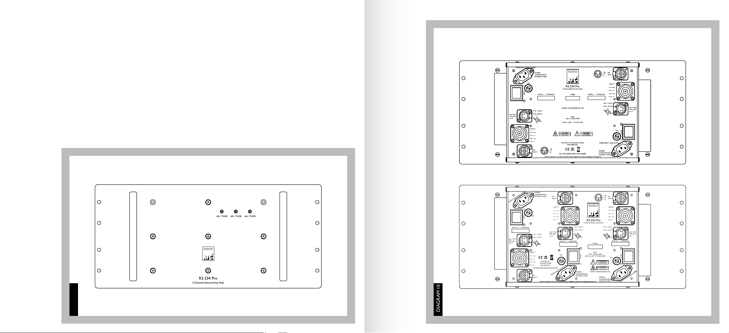
R2-234 Pro & R3-234 Pro The 2-channel and 3-channel variants of the remote amp are designed to be mounted in a 19” rack. Front and rear
views are shown in diagrams 9,10 and 14. When rack mounting, the following guidelines must be followed.
1 Rack mount amplifiers with a minimum of 1U free space above AND below each unit.
2 When blanking free spaces above/below amplifiers, vented rack panels must be used.
3 Only fit into racks with ventilated side and top panels and take care not to block top panel venting.
4 Take care to secure amplifiers using screws in all four rack mounting points – the amplifiers are heavy.
5 Take care that the ambient temperature in the space the amplifiers is mounted in does not exceed 30 deg C. If you as the user are uncomfortable
in a space, don’t site an amplifier there.
Above all, use common sense and, if in doubt, allow extra ventilation. This will result in a lower operating temperature and extend the life of
the product.
Failure to comply with the guidelines above could result in the amplifiers failing prematurely. Running the amplifiers for extended
time periods at high temperature will reduce the life of the product.
SECTION THREE
SCM25Ai Pro Mk2Remote Amp Installation
3.4
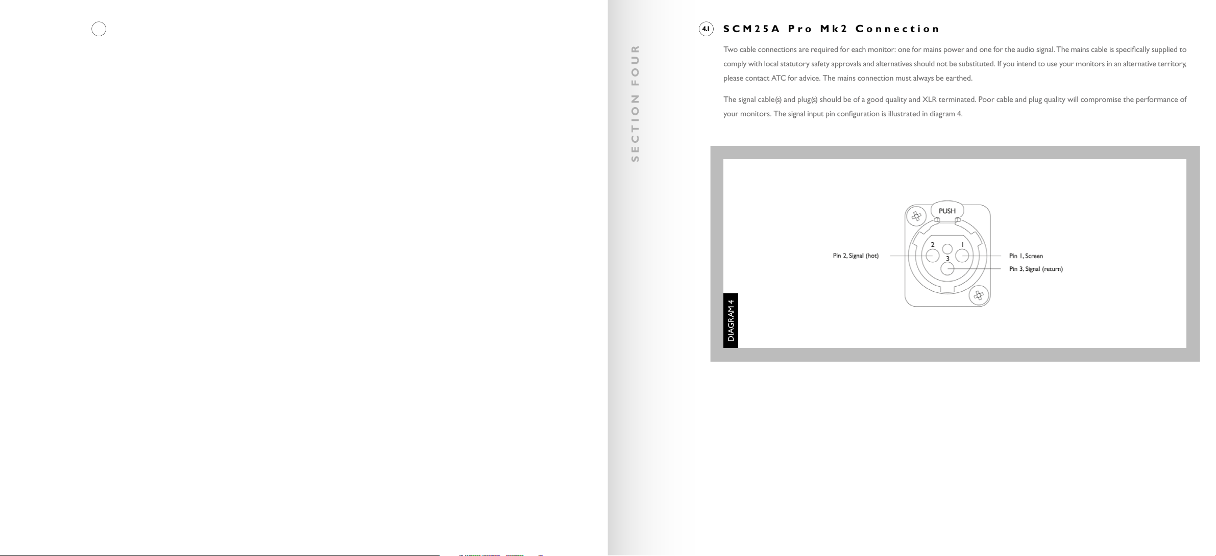
Two cable connections are required for each monitor: one for mains power and one for the audio signal. The mains cable is specifically supplied to
comply with local statutory safety approvals and alternatives should not be substituted. If you intend to use your monitors in an alternative territory,
please contact ATC for advice. The mains connection must always be earthed.
The signal cable(s) and plug(s) should be of a good quality and XLR terminated. Poor cable and plug quality will compromise the performance of
your monitors. The signal input pin configuration is illustrated in diagram 4.
SECTION FOUR
SCM25A Pro Mk2 Connection
4.1
DIAGRAM 4

Balanced cable configuration is the preferred option, however unbalanced connection is possible. Diagram 5 illustrates the signal cable connections
required for each option. Balanced (XLR to XLR) connection offers lower noise and better immunity to “hum” pick-up. Unbalanced (XLR to Phono
or Two Pole Jack) connection carries risk of hum caused by multiple signal earths.
Hum problems resulting from unbalanced connection may be reduced by making one of the following modifications to the signal cable connections:
If the driving preamplifier (or desk) is “double insulated” (i.e. has no mains earth), disconnect the signal cable screen at the RCA Phono plug end.
Alternatively, disconnect the signal cable screen at the XLR end. This second option will make the source the reference signal earth.
The SCM25Ai Pro Mk2connects to its remote mounted amplifier via connector panel in the rear face fitted with a Neutrik NL8 socket (for speaker
level audio) and a 5-pin female XLR connector (for power ‘on’/limiter ‘active’ LED indicator). See diagram 6.
The connectors fitted to the SCM25Ai Pro Mk2are mirrored on the partnering amplifier.
Amplifiers and speakers are matched during production. Be sure to connect a speaker to its partnering amplifier. Serial numbers on the rear of the
amplifiers identify partnering loudspeakers.
Two types of cable are required:
1 NL8 to NL8 using 6 or 8-core speaker cable. Cables use connector pairs 1, 3, 4 wired pin-to-pin. Connector pair 2 is not connected.
ATC recommend a minimum cable conductor area of 2.5mm2/14G for cable runs of up to 5m/16’ and 4.0mm2/12G for runs up to 10m/33’.
2 Male 5-pin XLR to male 5-pin XLR. Cables use connector pins 1, 2, 3 and 4, wired pin-to-pin.
SECTION FOUR
SCM25A Pro Mk2Cable Options SCM25Ai Pro Mk2Connection
4.2 4.3
DIAGRAM 6
DIAGRAM 5

SECTION FIVE
SECTION SIX
Power on/off Powers the loudspeaker on or off. When the switch is in the downward position, the switch lamp is illuminated, and the loudspeaker
is powered on. When the switch is in the upward position the switch lamp is not illuminated and the loudspeaker is powered off.
Due to the nature of the electronics in ATC active loudspeakers it is quite normal for a sound to be heard from the speaker when the power is applied or disconnected.
The noise heard will not damage the speaker and is quite normal. Although ATC uses the highest-grade components, a different noise may be heard from each speaker
due to slight tolerance variations in the amplifier components.
Bass Boost Adjustable with a “trimming tool” and accessed through the panel, this control allows for a variable bass boost from 0dBto +3dB.
Input Sensitivity Adjustable with a “trimming tool” and accessed through the panel, this control allows for the input sensitivity to be adjusted
from 1V to 2V/ 2.2dBu to 8.2dBu (-6dB).
Front Panel Display Indicates operational state. The SCM25A Pro Mk2has one bi-colour LED mounted in the front facing badge (see diagram 8).
The LED is lit Green when the loudspeaker is powered on.
The LED will turn Red when the amplifier is limiting, please reduce the listening level. Persistent and/or continuous illumination of the Red LED can
result in damage to the amplifier or loudspeaker drive units.
The user features/controls of the R1-234 Pro amp are identical to the SCM25A Pro Mk2 amplifier. As a result, please refer to section 5 above.
Power on/off Powers a single amp channel on or off. The 2-channel R2-234 Pro features two power switches, the 3-channel R3-234 Pro features
three. The power switches are located on the rear panel, as shown in diagram 10. When the switch lamp is illuminated, the amplifier channel is
powered on. When the switch lamp is not illuminated the amplifier channel is powered off.
Due to the nature of the electronics in ATC active loudspeakers it is quite normal for a sound to be heard from the speaker when the power is applied or disconnected.
The noise heard will not damage the speaker and is quite normal. Although ATC uses the highest-grade components, a different noise may be heard from each speaker
due to slight tolerance variations in the amplifier components.
Bass Boost This control is internal and only accessible by removing the top or bottom cover of the amplifier. As a result, adjustment should only
be made by a qualified technician, authorised ATC dealer or distributor. This control allows for a variable bass boost from 0dB to +3dB. Adjustment
is made via a PCB mounted trimmer and an appropriate “trimming tool” should be used to avoid damage.
Input Sensitivity This control is internal and only accessible by removing the top or bottom cover of the amplifier. As a result, adjustment should
only be made by a qualified technician, authorised ATC dealer or distributor. This control allows for the input sensitivity to be adjusted from 1V to
2V / 2.2dBu to 8.2dBu (-6dB). Adjustment is made via a PCB mounted trimmer and an appropriate “trimming tool” should be used to avoid damage.
SCM25A Pro Mk2 Operation
5.1
DIAGRAM 8
DIAGRAM 7
R1-234 Remote Amp Operation
R2-234 Pro & R3-234 Pro Remote Amp Operation
6.1
6.2
SECTION SIX
Front Panel Display Indicates operational state. The R2-234 Pro has two bi-colour LEDs mounted in the front panel, the R2-234 Pro has three.
Each LED is linked to a corresponding amp channel (See diagram 9).
The LED is lit Green when the amplifier is powered on.
The LED will turn Red when the amplifier bass channel is limiting, please reduce the listening level. Persistent and/or continuous illumination of the
Red LED can result in damage to the amplifier or loudspeaker drive units.
The LED indicators are also featured in the partnering SCM25Ai Pro speakers (see diagram 8). The LED behaviour is identical to that in the amplifier.
DIAGRAM 10
DIAGRAM 9
bal.
input 1
bal.
input 2
bal.
input 3
pwr / limit
LED drive
out 2
pwr / limit
LED drive
out 1
pwr / limit
LED drive
out 3
output 2
1+/1- : bass
2+/2- : n/c
3+/3- : mid
4+/4- : hf
fuses:
115V : T6.3AH 250V
220V to 230V: T3.15AH 250V
21
3
1:
2:
3:
RETURN TO
MANUFACTURER
FOR DISPOSAL
NO USER SERVICEABLE PARTS INSIDE
CAUTION
RISK OF ELECTRIC SHOCK
DO NOT OPEN
WARNING
THIS EQUIPMENT
MUST BE EARTHED
!
CHECK VOLTAGE BEFORE USE
output 1
1+/1- : bass
2+/2- : n/c
3+/3- : mid
4+/4- : hf
output 3
1+/1- : bass
2+/2- : n/c
3+/3- : mid
4+/4- : hf
power
power
power
POWER
CONSUMPTION
425 WATTS MAX.
MAINS INPUT 50/60 Hz
fuse
fuse
fuse
MAINS INPUT 50/60 Hz
MAINS INPUT 50/60 Hz
POWER
CONSUMPTION
425 WATTS MAX.
POWER
CONSUMPTION
425 WATTS MAX.
voltage
1: bass - on/green
2: bass - limit/red
1
2
Green
Red
1: bass - on/green
2: bass - limit/red
1
2
Green
Red
Green
Red
1: bass - on/green
2: bass - limit/red
1
2
Green
Red
R3-234 Pro
3-Channel Remote Amp Pack
serial no. / loudspeaker
serial no. / loudspeaker
serial no. / loudspeaker

The ear and brain tend to interpret distorted sound as loudness and thus underestimate the actual level of undistorted sound. The SCM25A Pro
Mk2and SCM25Ai Pro Mk2, like all ATC monitors, demonstrate much lower levels of distortion than conventional systems of a similar size and it
is therefore advisable to begin listening at an artificially low level and carefully increase the volume. It is also possible for the monitors to produce
sufficient sound pressure levels for your ears themselves to become a source of distortion and make the sound appear harsh. Any audible distortion
indicates that either the system or your ears are being overloaded and that the volume level should be reduced.
Listening
7.1
SECTION SEVEN
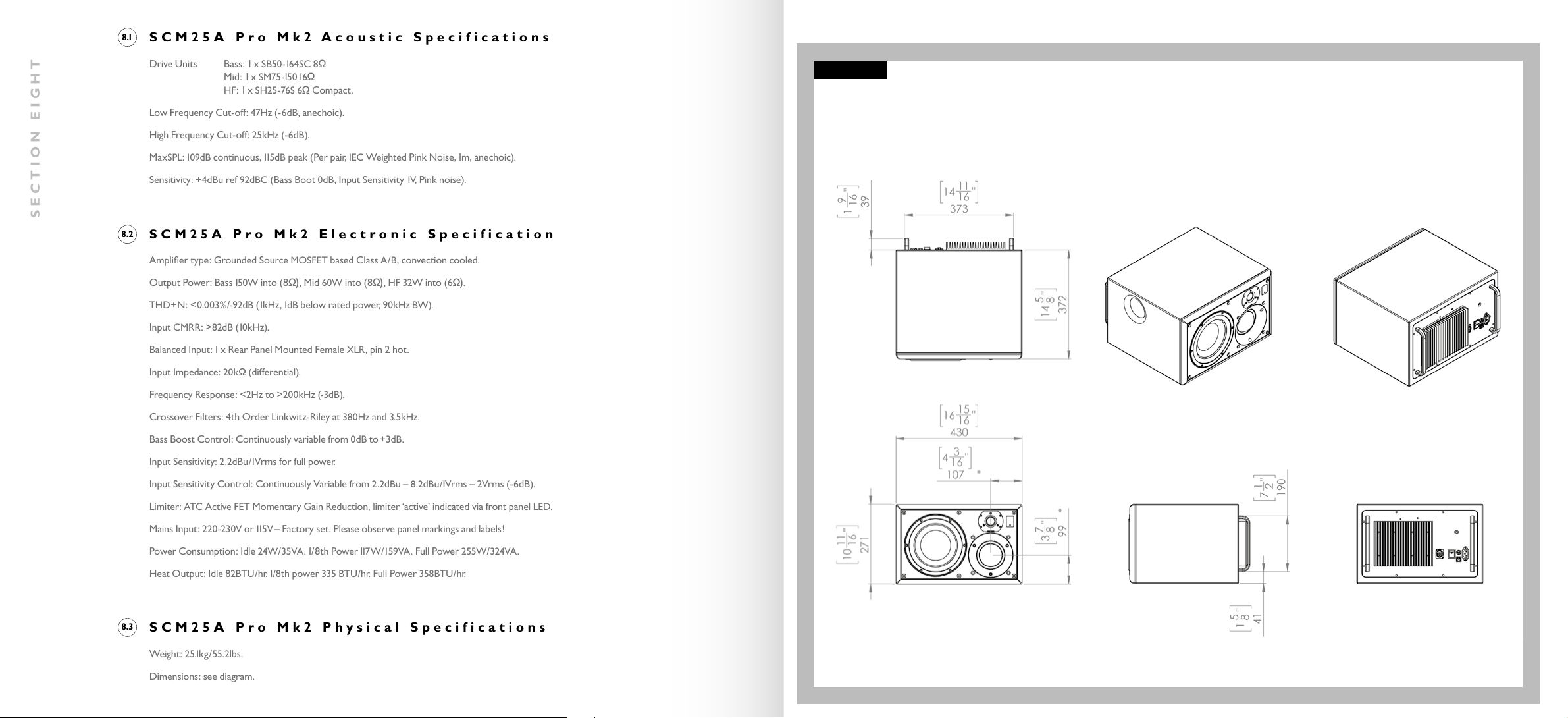
Drive Units Bass: 1 x SB50-16 4 S C 8 ΩΩ
Mid: 1 x SM75-15 0 16 ΩΩ
HF: 1 x SH25-76S 6ΩΩCompact.
Low Frequency Cut-off: 47Hz (-6dB, anechoic).
High Frequency Cut-off: 25kHz (-6dB).
MaxSPL: 10 9dBcontinuous, 115 dBpeak (Per pair, IEC Weighted Pink Noise, 1m, anechoic).
Sensitivity: +4dBu ref 92dBC (Bass Boot 0dB, Input Sensitivity 1V, Pink noise).
Amplifier type: Grounded Source MOSFET based Class A/B, convection cooled.
Output Power: Bass 15 0 W into (8Ω), Mid 60W into (8Ω), HF 32W into (6Ω).
THD+N: <0.003%/-92dB(1kHz, 1dBbelow rated power, 90kHzBW).
Input CMRR: >82dB(10 kHz).
Balanced Input: 1 x Rear Panel Mounted Female XLR, pin 2 hot.
Input Impedance: 20kΩΩ(differential).
Frequency Response: <2Hz to >200kHz (-3dB).
Crossover Filters: 4th Order Linkwitz-Riley at 380Hz and 3.5kHz.
Bass Boost Control: Continuously variable from 0dBto +3dB.
Input Sensitivity: 2.2dBu/1Vrms for full power.
Input Sensitivity Control: Continuously Variable from 2.2dBu – 8.2dBu/1Vrms – 2Vrms (-6dB).
Limiter: ATC Active FET Momentary Gain Reduction, limiter ‘active’ indicated via front panel LED.
Mains Input: 220-230V or 115 V – Factory set. Please observe panel markings and labels!
Power Consumption: Idle 24W/35VA. 1/8th Power117 W / 1 59 VA . Full Power 255W/324VA.
Heat Output: Idle 82BTU/ h r. 1/8th power 335 BTU/hr. Full Power 358BTU/ h r.
Weight: 25.1kg/55.2lbs.
Dimensions: see diagram.
SECTION EIGHT
SCM25A Pro Mk2 Acoustic Specifications
SCM25A Pro Mk2Electronic Specification
8.1
8.2
SCM25A Pro Mk2 Physical Specifications
8.3
DIAGRAM 11
SCM25A PRO MK2

Drive Units Bass: 1 x SB50-16 4SC 8Ω
Mid: 1 x SM75-15 0 16 Ω
HF: 1 x SH25-76S 6ΩCompact.
Low Frequency Cut-off: 47Hz (-6dB, anechoic).
High Frequency Cut-off: 25kHz (-6dB).
MaxSPL: 109dBcontinuous, 115 d B peak (Per pair, IEC Weighted Pink Noise, 1m, anechoic).
Sensitivity: +4dBu ref 92dBC (Bass Boot 0dB, Input Sensitivity 1V, Pink noise).
Speaker Level Input: 1 x Rear Panel Mounted Neutrik NL8.
Power/Clip LED Input: 1 x Rear Panel Mounted 5-Pin Female XLR.
Weight: 19.3kg/42.5lbs.
Dimensions: see diagram.
SECTION EIGHT
SCM25Ai Pro Mk2Acoustic/Loudspeaker Specifications
SCM25Ai Pro Mk2Physical Specifications
8.4
8.5
10 11
16
"
271
16 15
16
"
430
37
8
"
99
*
43
16
"
107
*
5"
127
213
16
"
72
23
4
"
70
95
16
"
236
12 9
16
"
319
16 15
16
"
430
SUPPLIED IN MIRROR IMAGE PAIRS. LEFT SPEAKER SHOWN
* ACOUSTIC CENTRE
D
E
F
C
1
2
3
4
B
A
3
2
1
5
C
D
4
6
7
8
A
B
1:8
A3
5
6
7
8
E
F
DO NOT SCALE - IF IN DOUBT ASK !
STRICTLY PRIVATE AND CONFIDENTIAL - ADDRESSEE ONLY
ASSY - SCM25Ai PRO MK2
REV
DRAWN
***
***
WEIGHT
MATERIAL:
05-01-23
PROJECT
TOLERANCES UNLESS OTHERWISE STATED
MODIFICATION
APPV'D
©LOUDSPEAKER TECHNOLOGY LTD 2012
ALL RIGHTS RESERVED.
This form and any attachments to it, may not be
reproduced or transmitted, in any form or by any
means, or stored in any system, without the prior
written consent of Loudspeaker Technology Ltd,
and if requested, must be immediately returned
to LoudspeakerTechnology Ltd.
SCALE
LOUDSPEAKER TECHNOLOGY LTD
GYPSY LANE
ASTON DOWN
STROUD
GLOUCESTERSHIRE GL6 8HR
TELEPHONE: 01285 760561
www.atc.gb.net
***
SCM25A PRO MK2
A
REV
*
00-00-00
SHEET METAL DIMENSIONS
INTERNAL EXTERNAL
UNDER 15 : +0.20 -0.20
15 TO 100 : +0.35 -0.35
OVER 100 : +0.50 -0.50
THIRD ANGLE PROJECTION
***
TITLE
CHK'D
MACHINED DIMENSIONS
ONE DECIMAL PLACE : +/- 0.25MM
TWO DECIMAL PLACES: +/- 0.10MM
ANGULAR: +/- 0.50DEG
NEW DRAWING - SOLIDWORKS
All copyright, design rights and any other intellectual property rights in
the contents of, or in any attachments to, this form, to include any plans,
design, photographs, specifications and other materials, remain the
exclusive property of Loudspeaker Technology Ltd, are strictly private
and confidential, and may not be reproduced or transmitted, in any form
or by any means, or stored in any system, without the prior written
consent of Loudspeaker Technology Ltd and, if requested, must be
immediately returned to Loudspeaker Technology Ltd.
PAPER
DWG NO.
RJN
***
FINISH:
***
ALL DIMENSIONS IN MILLIMETRES U.O.S. - REMOVE SHARP EDGES
DATE
SCM25Ai PRO MK2
A
REMOVE ALL BURRS & SHARP EDGES
1.
(BREAK ALL EDGES - MAX 0.2 RAD)
PLEASE PACK & HANDLE TO AVOID ANY
2.
DENTS, BRUISING & SCRATCHES
THIS IS A COSMETIC PART
3.
THERE MUST BE NO VISIBLE MACHINING MARKS
4.
SHEET 2 OF 2
DIAGRAM 12
SCM25AiPRO MK2
Amplifier type: Grounded Source MOSFET based Class A/B, convection cooled.
Output Power: Bass 15 0 W (8Ω), Mid 60W (8Ω), HF 32W (6Ω).
THD+N: <0.003%/-92dB(1kHz, 1dB below rated power, 90kHzBW)
Frequency Response: <2Hz to >200kHz (-3dB).
Crossover Filters: 4th Order Linkwitz-Riley at 380Hz and 3.5kHz.
Balanced Input: Front Panel Mounted Female XLR, pin 2 hot.
Input CMRR: >82dB(10 kHz).
Input Impedance: 20kΩ(differential).
Input Sensitivity: 2.2dBu/1Vrms for full power.
Input Sensitivity Control: Continuously Variable from 2.2dBu-8.2dBu/1Vrms-2Vrms (-6dB).
Speaker Level Output: Rear Panel Mounted Neutrik NL8.
Bass Boost Control: Continuously variable from 0dBto +3dB.
Limiter: ATC Active FET Momentary Gain Reduction, limiter ‘active’ indicated via LED on speaker front panel.
Power/Clip LED Output: 1x Rear Panel Mounted 5-Pin Female XLR.
Mains Input: 220-230V or 115 V – Factory set. Please observe panel markings and labels!
Power Consumption: Idle 24W/35VA. 1/8th Power 117 W /159 VA . Full Power 255W/324VA.
Heat Output: Idle 82BTU/ h r. 1/8th power 335 BTU/hr. Full Power 358BTU/ h r.
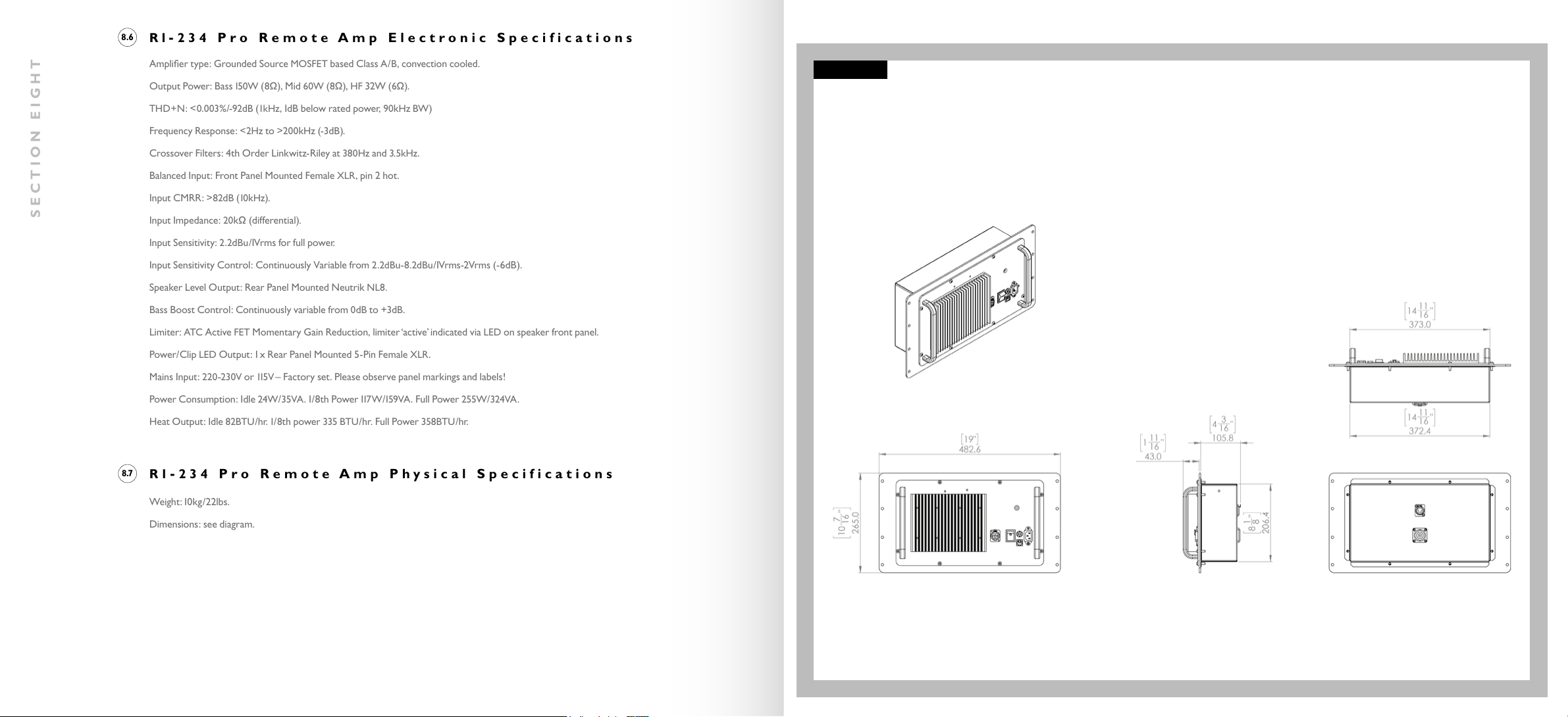
Weight:10kg/22lbs.
Dimensions: see diagram.
SECTION EIGHT
R1-234 Pro Remote Amp Electronic Specifications
R1-234 Pro Remote Amp Physical Specifications
8.6
8.7
R1-234 PRO REMOTE AMP
DIAGRAM 13
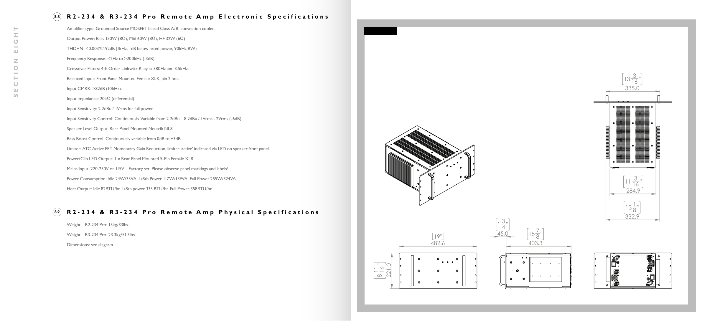
Amplifier type: Grounded Source MOSFET based Class A/B, convection cooled.
Output Power: Bass 150W (8Ω), Mid 60W (8Ω), HF 32W (6Ω)
THD+N: <0.003%/-92dB (1kHz, 1dB below rated power, 90kHz BW)
Frequency Response: <2Hz to >200kHz (-3dB).
Crossover Filters: 4th Order Linkwitz-Riley at 380Hz and 3.5kHz.
Balanced Input: Front Panel Mounted Female XLR, pin 2 hot.
Input CMRR: >82dB (10kHz).
Input Impedance: 20kΩ(differential).
Input Sensitivity: 2.2dBu / 1Vrms for full power
Input Sensitivity Control: Continuously Variable from 2.2dBu – 8.2dBu / 1Vrms - 2Vrms (-6dB)
Speaker Level Output: Rear Panel Mounted Neutrik NL8
Bass Boost Control: Continuously variable from 0dB to +3dB.
Limiter: ATC Active FET Momentary Gain Reduction, limiter ‘active’ indicated via LED on speaker front panel.
Power/Clip LED Output: 1 x Rear Panel Mounted 5-Pin Female XLR.
Mains Input: 220-230V or 115V – Factory set. Please observe panel markings and labels!
Power Consumption: Idle 24W/35VA. 1/8th Power 117W/159VA. Full Power 255W/324VA.
Heat Output: Idle 82BTU/hr. 1/8th power 335 BTU/hr. Full Power 358BTU/hr.
Weight – R2-234 Pro: 15kg/33lbs.
Weight – R3-234 Pro: 23.3kg/51.3lbs.
Dimensions: see diagram.
SECTION EIGHT
R2-234 & R3-234 Pro Remote Amp Electronic Specifications
R2-234 & R3-234 Pro Remote Amp Physical Specifications
8.8
8.9
DIAGRAM 14
R2-234 PRO REMOTE AMP

High technology material finishes are used in this product. The surfaces are durable and with a little care can be kept as good as new even under
conditions of heavy use. Normally, a dry duster will be all that is required to keep the finishes clean.
Heavy soiling can be cleaned using a cloth slightly moistened with a non-abrasive household cleaner.
There are no components within the speakers that can be considered expendable, or that would benefit from regular maintenance. There is no
requirement for any kind of routine service work and there is no schedule for preventative maintenance. There are no user-replaceable parts within
the speaker, and in the unfortunate event of any malfunction, repair should be referred to either the supplying dealer or consultant, the relevant
importer, or ATC . ATC has every confidence in the quality of each product that it manufactures.
All ATC products are guaranteed against any defect in materials or workmanship for a period of two years from the date of purchase. Within this
period, we will supply replacement parts free of charge provided that the failure was not caused by misuse, accident or negligence. Purchasers
who complete the Product Registration process, either by returning a completed Warranty Card to ATC or by registering the product at
www.atc.audio, will have their warranty period extended up to a period of six years from the date of purchase.
This guarantee does not limit statutory rights.
Loudspeaker Technology Ltd
Gypsy Lane, Aston Down
Stroud, Gloucestershire
GL6 8HR
United Kingdom
Te l e p h o n e + 4 4 ( 0 ) 12 8 5 76 0 5 61
Email: info@atc.audio
Website: www.atc.audio
Acoustic Transducer Company is the trading name and is the registered trade mark of Loudspeaker Technology Ltd.
Care & Maintenance
Warranty
Contact
9.1
9.2
9. 3
SECTION NINE
DIAGRAM 15
R3-234 PRO REMOTE AMP

Loudspeaker Technology Ltd
Gypsy Lane
Aston Down
Stroud
Gloucestershire
GL6 8HR
United Kingdom
Telephone +44 (0)1285 760561
Email: info@atc.audio
Website: www.atc.audio
Acoustic Transducer Company is the trading name.
is the registered trade mark of Loudspeaker Technology Ltd.
R
This manual suits for next models
2
Other ATC Speakers manuals


Popular Speakers manuals by other brands

Braven
Braven BZ600gba user manual

Martin Audio
Martin Audio F15A - SCHEMATICS manual

Anthony Gallo Acoustics
Anthony Gallo Acoustics Classico CL-C owner's manual

RCF
RCF CS 3082 owner's manual

Pan Acoustics
Pan Acoustics PAN SPEAKER Series technical information

KONIG ONSTAGE
KONIG ONSTAGE OSP-FX1152A user manual


