ATC HeatStat HS500 User manual

ATC Electrical & Mechanical,
ATC House, Broomhill Drive, Tallaght, D24 EF99, Ireland
-1-
ATC HeatStat Underfloor Heating Thermostat
Installation And Operation Manual
HS500
Power 220-240V AC 50/60Hz
Temperature Range (Display) 0° to 40°
Temperature Range (Adjustment) 5° to 35°
Temperature Display accuracy 0.5°C
Sensor type Internal 10kΩNTC
External 12kΩNTC @25°C
Program type 4 on/off per day (5+2)
Switching capacity (Relay) 16A Resistive. 1A Inductive
Working environment temperature 0° to 90°
Installation type Wall Mounted Connection Diagram
Specifications:
1. Read all instructions prior to installing this thermostat, failure to follow the instruc-
tions could damage the product or cause a hazardous condition.
2. Check the loading of the product you intend to connect to this thermostat to ensure
that the device is capable of switching the intended load. Do not connect the load if
it is rated higher than 16A.
3. After product installation is complete, follow the instructions given below to ensure
that the thermostat functions correctly.
4. This product must be installed by a qualified electrician.
IMPORTANT SAFETY INSTRUCTIONS
CAUTION
Always disconnect power before installation, Risk of Electric Shock
or Equipment Damage.
CAUTION
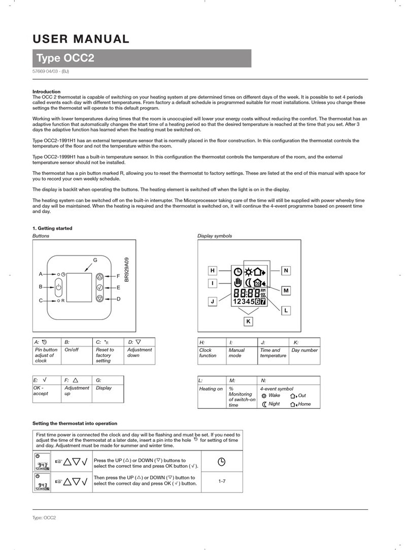
Thank you for purchasing the ATC HeatStat wall
mounted heating controller, your thermostat
is equipped with five touch sensitive buttons
across the bottom of the thermostat for easy
control and a large easy to read screen that is
optimised for viewing from above.
The HS500 is designed for both underfloor
heating control with the supplied floor sensor
and normal room control using the built in
highly accurate room sensor.

-2-
ATC Electrical & Mechanical,
ATC House, Broomhill Drive, Tallaght, D24 EF99, Ireland
MAIN SCREEN LAYOUT INFORMATION
PROGRAMMING
188.5
8888
f
188.
5
f
!
765432
1
On/Off
Set Key OK Key
Up Arrow
Down Arrow
Auto
Mode
Manual
Override
Floor
Sensor
Lock
Icon
Fault
Indicator
Floor
Temp
°C or °F
Indicator
Set Point
Temp
Mon to Fri
Sat & Sun
Current Time
Holiday
Mode
Heating
Indicator
Heating Mode Icons
Open
Window
Icon
Main Thermostat Screen Touch to turn the thermostat on and o.
1. Short touch to switch between Auto
and Manual mode.
2. Long touch with Stat turned on enters
into Programming mode.
3. Long touch with Stat turned o enters
into the Configuration mode.
1. Short touch to enter the time setting
mode.
2. Long touch to enter holiday mode con-
figuration.
1. Touch to decrease the temperature set-
point.
2. Long touch to lock or unlock the ther-
mostat.
1. Touch to increase the temperature
set-point.
2. Long touch to find out the external
temperature probe (when in room sensor
mode - see a4 in advanced functions).
3. When in Auto mode, touch up or down
arrow to change the temperature set-point
and enter into Manual mode (touch set to
return to auto mode).
The ATC HeatStat is factory set in a 5+2 configuration (Monday to Friday & Saturday/Sunday), it can also be set
for 6+1 and 7 days all the same (see “ac” in the advanced functions). The factory program is set as follows:
Heating
Mode
Icon
Function Wake Up Leave Home Return Home Go to Bed
Time Temp 06:00 20°C 08:00 15°C 17:00 15°C 22:00 15°C
SETTING THE TIME
To set the current time and day touch the key and the time
will start to flash; set the current minutes using the or
and touch , the hours can now be set in the same way. When the time is correct touch the key and
the days of the week will flash starting at 1 (Monday). Change to the correct day of the week and touch
to save the time.
In order to customise the program touch and hold the key and the display will change to show the time
for the First heating period flashing and the “12345” at the top of the screen. These numbers show that the
weekdays are being programmed. Use the & keys to adjust the time (hours then minutes); to move
to the next set-point use the key each time. Once the time is set, then the “Set Point Temp” will begin to
flash, set to the required value and press to store.

ATC Electrical & Mechanical,
ATC House, Broomhill Drive, Tallaght, D24 EF99, Ireland
-3-
Repeat this process for each of the times and temperatures required for each day. Once the Monday to
Friday times have been set the will begin to flash to indicate that Saturday and Sunday are being
programmed. Complete the times and temperatures required. Once the programming has been completed
then the thermostat will return to Auto mode as shown by: , leaving the thermostat alone for 20 seconds
will also return to the previous mode of operation.
At any time the temperature setting can be adjusted with the & keys and the display will change from
Auto to show the Manual Override symbol: . To return to automatic operation touch the key.
HOLIDAY MODE
To set the thermostat into holiday mode where it will override the standard program for a number of days (1-30
days) touch and hold the key until the time changes to “0ff”, use either or to change the display
to “0n” and touch . The Main Temperature display will show “01” change this to the number of days Hol-
iday mode should be active for and touch . Now the Set Point Temperature will start to flash, change the
set-point to the temperature to be maintained for the holidays and touch . The display will change to show
the Holiday Icon: . To return to normal operation touch .
KEY-LOCK
To lock the keys to prevent any accidental changes touch and hold the key. The display will show the lock
icon: . To unlock hold the key until the lock icon disappears.
ADVANCED FUNCTIONS
To configure the thermostat in a dierent mode to the factory setting, turn the unit o with the key, and
touch and hold the key, there are 14 settings from a1 to a9 and aa to ae as outlined below. To adjust the
setting use the or and to save the value and move onto the next setting. If the thermostat is left
for 20 seconds the menu will revert to o. Note: Manual Mode available in Item ac
Item Function Description of function and range of information. Factory
Default
a1 Display
temperature
oset.
-9°C to +9°C.
Default will display current temp with 0.5°C Accuracy
Current
Temp
a2 Temperature
control return
dierence.
0.5°C to 2.5°C. 1°C.
a3 External sensor,
limit temperature
control dierence
1°C to 9°C. 2°C.
a4 Control type
options.
n1: Internal sensor with high temperature protection to turn stat o.
(Room Stat)
n2:External sensor with high temperature protection to turn stat o
(Floor Stat)
n3: Internal sensor with external sensor as high level limit (a6).
When external temperature exceeds value, relay is turned o.
(Room and Floor Stat).
n2
a5 Key Lock. 0: Does not include Power key. 1: Includes Power key. 0

-4-
ATC Electrical & Mechanical,
ATC House, Broomhill Drive, Tallaght, D24 EF99, Ireland
SENSOR FAULT
a6 High Limit value
for external
sensor.
Only available when a4=n3
Range 25°C→75°C, when set to less than 25°C setting shows “--”
and protection is turned o.
If the high limit setting is exceeded the relay is turned o and the
heating symbol will flash until the temperature falls below the setting.
45°C
a7 External sensor
Low Limit.
Range 1°C→10°C, (anti freeze protection). When set to more than
10°C setting shows “--” and protection is turned o.
5°C
a8 Lowest settable
temperature.
1°C to 10°C. 5°C
a9 Highest settable
temperature.
20° to 90°C.
(Use this setting for wooden floors, set to 28°C).
35°C
aa Descaling
function.
0: Descaling function o.
1: Descaling function on. If output is continuously closed for 100
hours or more, contact is open for 3 minutes.
0
ab Power and
memory function.
0: Always retain program memory.
1: Reset program memory after removing mains power.
2: Reset program memory when making mains power connection.
0
ac Type of
Programming
selection.
0: 5+2 (Mon→Fri, Sat & Sun). 1: 6+1 (Mon→Sat, Sun).
2: 7 (7 Days all the same). 3: Manual mode, No program
functions, only for time and arrows for temperature.
0
ad Open Window
mode- o
duration.
5 to 60 minutes. If temperature drops 3°C in 30 minutes the relay is
deactivated for the set duration and display shows . To reset
whilst function is active turn stat o and on again. (If setting is set
to less than 5 minutes, shows “--” and function is disabled).
30
ae Factory Reset. Display shows a,, press and hold . Display shows all icons and
then switches o. All settings apart from time are lost.
a,
INSTALLATION METHOD
The thermostat may show an e1 or e2 on the display. This is because the sensor is not connected correctly;
it may be due to an open circuit or the heat mat may be connected in terminals 5 and 6. Check the resistance
of the sensor, it should be 12kΩ@25°C. If the mat was inadvertently connected in 5&6 the resistance would be
between 21Ω and 756Ω, these low resistances will cause the thermostat to display an error.
Once the resistances are checked, replace the sensor or mat as appropriate.
WARRANTY
ATC Electrical and Mechanical provides a limited one year warranty for the HS500 thermostat as long
as the unit has been installed, used and maintained in accordance with the information provided in
this manual. In order to arrange a replacement thermostat, the information listed below is required.
It is recommended to write this information below and keep this instruction manual in a safe place.
Date of Purchase: Location Purchased:
Table of contents
Other ATC Thermostat manuals