Atcall SuperLink SF005A User manual

A cell booster specially created for the young
NEED HELP ?
SuperLink
Cell Signal Booster
Installation Guide
Atcall
3-year manufacturer‘s warranty

CATALOG
Package Contents
Install the Booster
STEP 1:
Safety Guidelines
Specifications
Warranty
Mount & Point Outside Antenna Toward Nearest
Cell Tower
STEP 2:
Preparation
Route & Connect Outside Antenna To Booster
STEP 3 :
Power Up The Booster & Optimize The System
STEP 4 :
Installation – LCD Display Method
Measuring Booster Performance
1
2
11
13
16
17
18
4
9
10
3

Package
Contents
1
SuperLink(Built in
Antenna)
Outside
Antenna
60ft of
RG6 Cable
Power
Supply
Roof/Pole
Mount
Bracket

Preparation
You Will Need (tools not included)
Make sure the following materials are prepared and ready for your
installation.
NOTE: These instructions will walk you through a “soft” install process to
find the optimal locations for the inside and outside antennas, then
through the process of the permanent installation.
1 to 2 hours
2 people (a person to help antenna calibration)
pLadder
pDrill (if routing cable through wall)
p1”-3” diameter existing pole for mounting
Outdoor Antenna (Pole Mount can be purchased
separately if needed)
pRecommended: Power Strip with surge protection
2

Booster will about 30 degrees Fahrenheit higher than the ambient
temperature, which is a normal phenomenon.
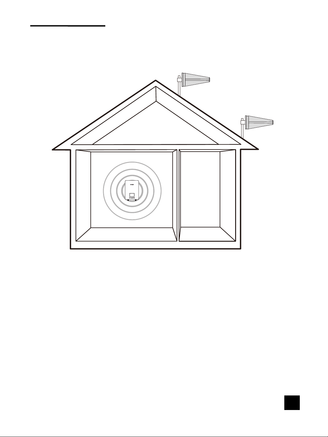
Step 1: Install the Booster
Install the Booster with built-in indoor antenna where you need the
greatest signal boost and place it in your desired location. Mount the
signal booster in a ventilated and dry place that is easily accessible
for maintenance (it should be located near a power outlet)
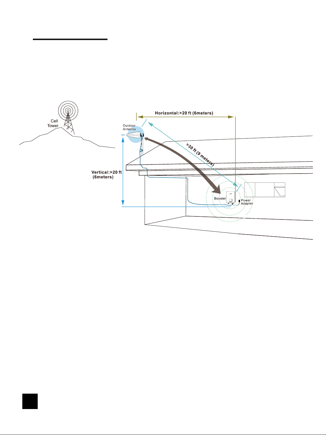
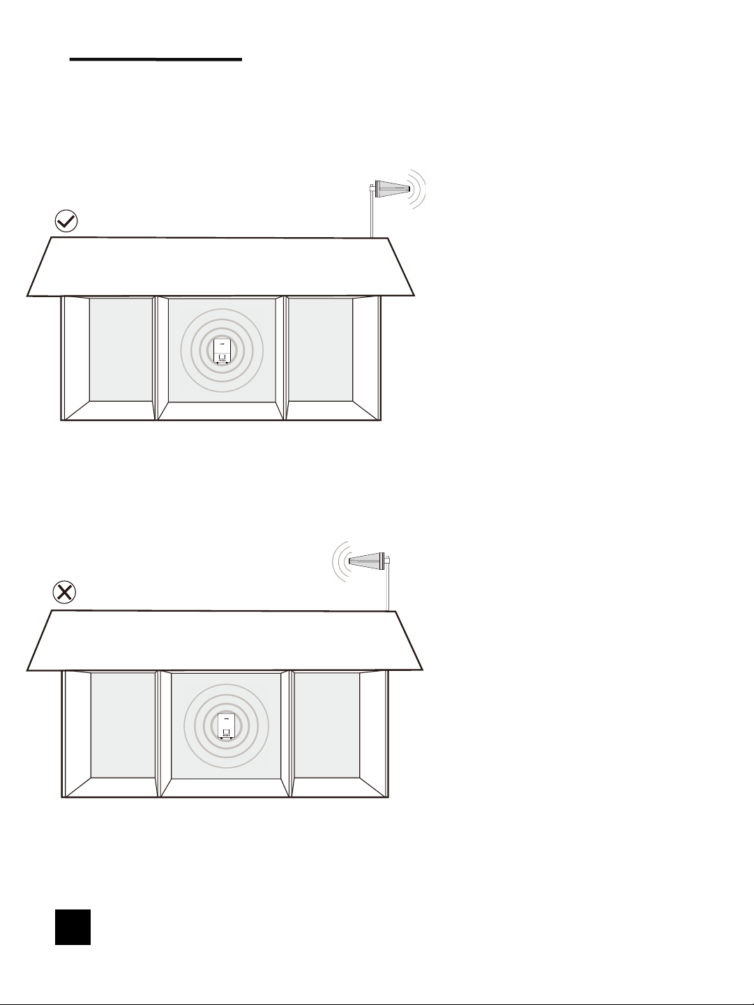
While choosing a location for the booster, please keep in mind that there
must be at least 20 ft of vertical separation between the outdoor antenna
and the booster with built-in indoor antenna.
NOTE: Do not connect booster to power until the system is fully installed.
3
sideview
tapping screw
Mounting booster with
built-in indoor antenna
on wall bracket

Step 2: Mount & Point
Outside Antenna Toward
Nearest Cell Tower
Pole mounting and wall mounting options are included. The pole
mounting option is preferred because it will be easier to adjust to the
direction of the cell tower.
Attach the Mount to the Outside Antenna and use the Bracket Clamps
to attach the Antenna to a pole or exhaust pipe.
Make sure that the outside unit is mounted at least 3 feet away from any
windows.
Outdoor antenna must be installed over the roof line.
NOTE: Mounting on existing roof exhaust pipe would be a
good time-saver option. Watch out for power lines.
① ②
③
4

Point the Outside Antenna toward the nearest cell phone tower. To find
the nearest tower, use an app such as 'Open Signal'. This is the most
critical step of the installation process because it will determine the
overall performance of the booster system.
5

Keep enough distance between outside antenna
and booster
NOTE:
The Outside Antenna must be at least 30 feet (9 meters) Straight line
distance or
20 feet (6 meters) horizontal
20 feet (6 meters) vertical from the booster with built-in indoor antenna for
best performance.
The greater the separation between the Booster with built-in indoor
antenna and Outside Antenna, the better performance you will get from
the booster.
6

Select the optimal mounting location for the outside
antenna
After identifying the area of strongest signal, choose the surface where you will
mount your outside antenna.
1. The location should allow for sufficient separation between the outside
antenna and inside antenna.
2. In order to better receive external signals, the outside antenna is best
installed in a higher position on the house, but please pay attention to lightning
protection.
Best
OK
7

Booster and Antenna mutual position
The outside antenna should
be oriented in a way that it
does not “face” the
booster with built-in indoor
antenna.
Caution: Do not aim an
outside antenna towards
the booster with built-in
indoor antenna.
8

Step 3: Route & Connect
Outside Antenna To Booster
Connect the 60ft RG6 Cable to Outside Antenna and route cable into the
home, secure the cable near the antenna. All connections should be finger
tightened only.
Route cable to the Booster and connect to the port labeled 'OUTSIDE'.
9

Step 4: Power Up The
Booster & Optimize The
System
Plug in the Power Supply and connect it to the nearest power outlet.
NOTE: We strongly recommend using a power strip with surge protection.
10

11
Installation – LCD Display
Method
These are instructions that will allow users to install a Plus cell phone booster
using the LCD Display.
Before using this method, please take a moment to become familiar with the
LCD display, LED status indicators and control buttons on the booster.
Main Interface
Downlink signal strength
Frequency Band
info
Operating Status of the
corresponding Frequency
Band
There are five buttons located in the lower position of the booster, the
functions of the keys from left to right are: the left selection key, the right
selection key, confirm / setting / switch key, back to the previous interface key,
system upgrade key.

Detail Interface
Frequency Band
Switch status
prompt Message
1.Page switching
a) Main Interface -> Detail Interface
Select with the left and right keys and press the middle confirm button to enter
the detail page about the corresponding frequency band.
b) Detail Interface -> Main Interface
Press the back to the previous interface key to return to the main interface.
2.Frequency Band on and off
After entering the detail interface, select with the left and right keys and
press the middle confirm button to switch the corresponding frequency band on
and off.
12

Measuring Booster
Performance
How To Get Signal Strength As A Number
iPhone®
Android™
iOS 11 and later no longer displays the decibel (dBm)
reading in 'Field Test Mode'. Tip: Using the dot signal
strength indicator on your cell phone can assist you in
finding the strongest signal direction as well as placing
calls in different locations.
Settings > About Phone > Status or Network > Signal
Strength or Network Type and Strength (exact
options/wording depends on phone model).
Android: download third part APP-LTE Discovery
iPhone is a registered trademark of Apple Inc. Android is a trademark of Google Inc.
Dial *3001#12345#* then press Call.
1 Hold down power button until you see 'Slide to
Power Off'.
2 Then release the power button.
3 Hold the Home button until your main screen appears.
If you want to check 3G/1x but your iPhone is picking up 4G/
LTE signal, go to Settings>Cellular>Cellular Data
Options>En_x0002_able .LTE>Select Off.
After you system is set up, you can go back to the dots signal
by once again dialing *3001#12345#* then pressing call.
When the menu comes back up, tap “phone” in the top left
corner of your phone.
iPhone®
iOS 11 - current
13

DID YOU KNOW a signal increase of just 3dB is 2 times the power
and signal amplification!
(MEASURING BOOSTER PERFORMANCE cont.)
Signal strength at 6 feet from the booster with built-in
indoor antenna
Note here:
Signal strength at 6 feet from outdoor antenna
Note here:
Compare Results
If the signal strength in decibels (dBm)at 6 feet from the indoor
antenna is 15-20dB higher than the signal strength at 6 feet from the
outdoor antenna, then your system has achieved the optimum results.
Note: Since it is a negative number, the smaller the number, the
greater the signal strength.
How To Confirm That Your Installation Is Correct And
Effective?
dBm
dBm
Having an accurate measurement of signal strength in decibels (dBm) is
crucial when installing your system. Decibels accurately measure the signal
strength you are receiving.
14

How to solve the problem of oscillation:
1. Keep enough distance between booster with built-in indoor
antenna and outside antenna
Minimum Required Separation Distance Between Booster and Ouside
Antenna:
Straight line distance over 30 feet(9 meters) or
20 feet (6 meters) horizontal distance
20 feet (6 meters) vertical distance (as far as possible).
2.The front of the outdoor antenna is NOT facing towards the booster with
built-in indoor antenna.
3. You may need to undo and redo the connection completely. Un-plug and re-
plug in power supply.
FIXING DC POWER INDICATOR OFF ISSUES
Please verify your power supply has power;
Please verify the power cord is tightened;
Contact with us by email or call for replacement.
15

To uphold compliance with network protection standards, all active cellular devices
must maintain at least six feet of separation distance from inside unit antenna and outside
unit antenna and at least four feet of separation distance from inside unit.
Use only the power supply provided in this package. Use of a non-Atcall product
may damage your equipment.
The Signal Booster unit is designed for use in an indoor, temperature-controlled
environment (less than 100 degrees Fahrenheit). It is not intended for use in attics or
similar locations subject to temperatures in excess of that range.
Sprint: http://www.sprint.com/legal/fcc_boosters.html
T-Mobile/MetroPCS: https://support.t-mobile.com/docs/DOC-9827
Verizon Wireless: http://www.verizonwireless.com/wcms/consumer/register-signal-booster.html
AT&T: https://securec45.securewebsession.com/attsignalbooster.com/
U.S. Cellular: http://www.uscellular.com/uscellular/support/fcc-booster-registration.jsp
FOR MORE INFORMATION ON REGISTERING YOUR SIGNAL BOOSTER WITH
YOUR WIRELESS PROVIDER, PLEASE SEE BELOW:
RF Safety Warning: Any antenna used with this device must be located at least 8
inches from all persons.
Safety Guidelines
This is a CONSUMER device
BEFORE USE, you MUST REGISTER THIS DEVICE with your wireless provider and have
your provider's consent .Most wireless provider consent to the use of signal boosters .Some
providers may not consent to the use of this device on their network .If you are
unsure ,contact your provider.
In Canada,BEFORE USE you must meet all requirement set out ISED CPC-2-1-05.
You MUST operate this device with approved antenna and cables as specified by the
manufacturer .Antennas MUST be installed at least 20cm (8inches) from(i.e.,MUST NOT be
installed within 20 cm of) any person.
You MUST cease operating this device immediately if requested by the FCC(or ISED in
Canada) or a licensed wireless service provider.
WARNING.E911 location information may not be provided or may be inaccurate for calls
served by using this device.
This device may be operated ONLY in a fixed location(i.e.,may operae
in a fixed location only) for in-building use.
This is a CONSUMER device
16

Specifications
NEED HELP ?
This device complies with Part 15 of FCC rules. Operation is subject to two conditions:
(1) This device may not cause harmful interference, and (2) this device must accept any
interference received, including interference that may cause undesired operation.
Changes or modifications not expressly approved by Atcall could void the authority to
operate this equipment.
17
Model Number
SF005A
Connectors
F-Female on the Inside Antenna / F-Female on the Outside Antenna
Noise figure
5 dB nominal
Antenna lmpedance
75 Ohms /75 Ohms
Weight
0.83Kg
Frequency
698-716MHz,776-787MHz,824-849MHz,1850-1915MHz,1710-1755MHz
728-746MHz,746-757MHz,869-894MHz,1930-1995MHz,2110-2155MHz
Power output for single cell phone
(Uplink)dBm
700A-MHz 700MHz 800MHz 1900MHz 1700MHz
Band12 Band13 Band5 Band2 Band4
62 62 62 65 65
Power output for single cell phone
(Downlink)dBm
700A-MHz 700MHz 800MHz 1900MHz 2100MHz
Band12 Band13 Band5 Band2 Band4
64 64 65 68 68
EIRP
1W Max
Operating temperature
5℉ to 140℉ (-15℃~60 ℃)
lsolation
>110 dB
Power Requirements
AC / DC 12V,1.5A, w/1.35X3.5mm Jack

DISCLAIMER: The information provided by Atcall is believed to be complete and
accurate, to the best of our knowledge. However, no responsibility is assumed by Atcall
for any business or personal losses arising from the use of the information herein
contained, or for any infringements of patents or other rights of third parties that may
result from its use.
2 Y2 YEAR WARRANTYEAR WARRANTY
3 YEAR WARRANTY
The Booster is covered under a three-year product warranty for failures or defects
that result from craftsmanship and/or materials. Dated proof of purchase should be
retained for use in warranty cases. Contact the retailer/reseller directly with any
warranty issues, or alternatively contact the manufacturer in cases where the
reseller is no longer available to handle warranty claims. In cases where the reseller
is unavailable, the product may be returned to the manufacturer at the consumer's
expense, with a dated proof of purchase and a return authorization letter which can
be attained by contacting Atcall.
This warranty does not apply to any signal booster components determined by
Atcall to have been subjected to misuse, abuse, neglect, tampering, or mishandling
that result in damages to the physical or electronic properties of the product.
Refurbished products that have been recertified to conform to product specifications
may be used for product replacements.
NEED HELP ? [email protected]
18
Notes:
Booster transmitting in 1710-1755 MHz should be install/operate in one of two ways:
(i) the antenna for the device must be installed to comply with the 10 meter above
ground maximum antenna height limitation OR
(ii) the antenna for the device has a 10 meter above ground maximum antenna height
limitation when the device is used with a handset that covers the 1710-1755 MHz band
and that owners could be subject to potential FCC enforcement action for noncompliance.
Table of contents