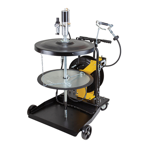
Instruction for Assembly of ATD5217 Lubrigun
Assemble Drum Cover to Pump
Insert end of pump tube (ATD5217-1) through hole in the drum cover
(45733). Line up holes in drum cover (45733) with the pump outlet body
(ATD5217-1). Place the screws (50060) in their respective holes in the
drum cover (45733) and tighten drum cover (45733) to the bottom of the
pump body (ATD5217-1)
NOTE: Many of the smaller parts might have already been installed for you, such a sthe muffler (2601) pump
cover (91407) and extention (10181).
Assemble the four casters (66060ME) to the roll around base (ATD5372)
1: Place a fresh drum of lubricant
centrally located on the roll around
base between the four base clamps
2: Base clamps are adjustable to fit
the various diameter drums.
3: Clamp drum rigidly to the base
by tightening the clamp studs
securely.
Insert follower plate (ATD5325) onto the bottom of the pump tube (ATD5217-1) and slide the follower plate
(ATD5325) up the pump tube.
Lower pump tube into lubricant until drum cover (45733) rests on top bead of drum.
Insert the three (3) adjusting screws (50415) into the drum cover (45733) and tighten securely to hold the
pump (ATD5217-1) to the drum.
Install the muffler (ATD5317)(not shown) in the exhaust port of the air motor head. Locate the muffler
(ATD5317) on the schematic. Ensure that the muffler (ATD5317) is inserted in the correct orifice.
Assemble the lubricant hose (ATD5361) to the pump outlet body. If the union adapter (66645ME) was
purchased, thread the union adapter into the lube opening followed by the hose (ATD5361) into the union
adapter. The connections must be leakproof. Do not connect the ATD5218 Control Valve Yet. You want
to prime the system and purge contaminants out of the Grease Hose.
Install the extention tube (10181) into the air inlet port of the air motor. You might need Teflon tape to ensure a leak-free
connection. Place air motor (91407) on pump head (ATD5217-1). Place washer (33034) and cover nut (11478) on pump
stud and thread air motor cover securely in place. Ensure that you align holes for 11660 air nipple and extension 10181.
The Air coupler (815ME) and nipple (11660) are packed in a separate bag.
Thread Air Nipple (11660) into extension (10181) connected through pump cover opening; Thread into pump head
opening. Use Teflon tape to seal threads to prevent air leakage if necessary.
Assemble air coupler (815) to an air hose of sufficient length so that the lubrigun can be moved to cover the
entire lubrication area with the hose attached. When air coupler (815) is attached to air coupler nipple
(11660), lubrigun is ready for operation. To release air coupler (815), draw back on the coupler sleeve (815)
and slide away from the nipple (11660).
NOTE: DO NOT INSTALL ATD5218 CONTROL VALVE YET!
Did you install? A regulator? We suggest that for accurate control of the pump, you use an air
regulator.
DID YOU: Purchase a Filter / Regulator for your pump? The Filter / Regulator should have
an automatic dump mechanism to purge the water out of the incoming air. Water
in the compressed air system is the biggest “Killer” of Air Operated Equipment.
YES: Proceed
NO: Think about it! It is cheap insurance to keep your pump running at maximum
efficiency and the pump will last longer.
Initiating Air Motor and Pump Operation
To Start Pump: Turn on air from Air Regulator slowly. You will hear the air enter the air motor. Pump will
start quickly and then reach prime at a stall pressure. It might take as much as 60-70 PSI to get the pump
started initially. Recommended Air Pressure to operate the pump under normal conditions is 80PSI. Pump
will activate as low as 15-20PSI. For first time operation, pump will start at 50-60 PSI. After that pump will
activate at the lower pressure.
Pump will start quickly and then reach prime at a stall pressure when the control valve is attached.


