ATECH CRATER-06 A User manual

1
CRATER-06 A
AUTOMATIC UPCUT MITER SAW
USER’S MANUAL

2
CONTENTS
1. General Information
1.1. Introduction
1.2. Distributor
2. Definition of the Machine and its Use
2.1. Definition of the Machine
2.2. Technical Features
2.3. Cutting Diagram
2.4. Overall Dimensions
2.5. Parts List and Technical Drawings
2.6. Electric and Pneumatic Control Panel
2.7. Pneumatic Circuit Scheme
2.8. Electric Wiring Scheme
2.9. Electric Circuit Scheme
3. Safety
3.1. Safety Information
3.2. Accident Prevention
3.3. General Safety Information
3.4. Safety Symbols ond their Meanings
4. Transport of the Machine
5. Installation of the Machine
5.1. Preparation
5.2. Electrical Connection
5.3. Air Pressure Adjustment
6. Machine Safety Information
7. Operation
7.1. Miter Cut
8. Safe Installation of the Saw Blade
9. Safe Installation of Motor Belt
10. Maintenance
10.1. Routine Controls, Maintenance and Work Starting
10.2. Discharging Air from the Hydro-Pneumatic Cylinder and Adding Oil
10.2.1. Dicharging Air from the Hydro-Pneumatic Cylinder
10.2.2. Adding Oil to the Hydro-Pneumatic Cylinder
10.3.Maintnance of the Spray Mist Lubrication System
10.4. Maintenance at the End of the Day
11. Troubleshooting Guide

3
1. GENERAL INFORMATION
1.1. INTRODUCTION
This user’s manual contains information about the machine and its operation.. Each machine operator should
read these instructions carefully, and the machine should be operated after fully understanding them.
Safe and efficient use of the machine for long term depends on understanding and following the instructions
contained in this manual. The technical dtawings and details contained in this manual constitute a guide for the
operator.
1.2. DISTRIBUTOR
ATech Machine, Inc.
8539 Ziggy Lane, Gaithersburg, MD 20877 – USA
Ph.: +1-240-505-1967 * Fax: +1-301-560-6627
*In case of any technical problem please contact your nearest ATECH dealer or ATECH head office through
the above mentioned phone, fax numbers or e-mail address.
*Technical labels with the model description of the machine are attached onto the front side of each machine.
* The machine serial number, motor data, air pressure, air consumption and production date are printed on the
technical label.
2. DEFINITION OF THE MACHINE AND ITS USE
2.1. DEFINITION OF THE MACHINE
This heavy duty upcut miter saw has been designed for cutting of aluminum & vinyl extrusions and wood. Cuts can
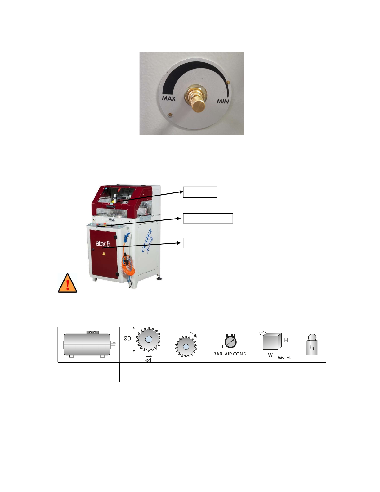
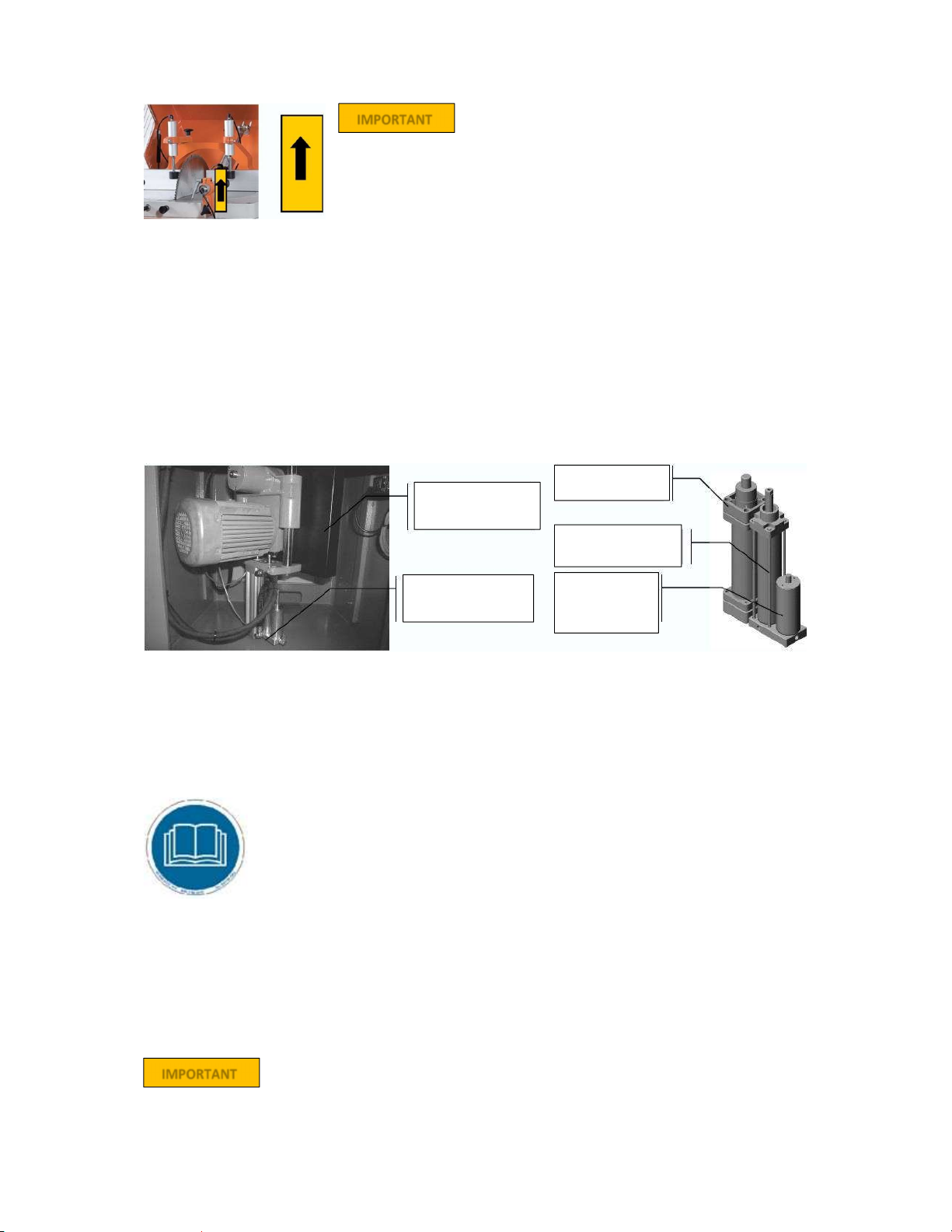
be made both straoght and miter cuts. The operator adjusts the rising speed of the saw blade (see Figure 1))
depending on the material to cut.
Miter cuts at 150- 22,50-300-450-900 are set via lock pin. Any intermediate angles are manually set by
tightening a bolt located on the turntable. You can also cut at 900 on the right side again with spring set.
The machine has been designed in full conformity with UL, CSA and CE Safety Directives.
The fence on the saw table consists of 2 parts, and can be moved back to allow larger straight cuts.
Rising speed of the saw blade is adjustable via know located on the left side, next to the control panel.
If the top guard is opened during the cutting process the saw blade stops and returns to its starting position
automatically for operator’s safety.
After the cutting process is completed, or once you release the cutting start buttons the saw blade moves
down o its starting position automatically.
STANDARD ACCESSORIES
Ø450 mm (18”) Carbide Tipped Saw Blade
Air Gun
Twin vertical & horizontal pneumatic clamps
Chip collector connection manifold
User’s Manual
OPTIONAL ACCESSORIES
Pneumatic Spray Mist Lubrication System
Infeed/Outfeed Table
Please mention the data below in every correspondence with your ATech Dealer or ATech Head Office.
Machine model
Machine’s serial number
Voltage and frequency
Name of dealer where machine was purchased
Date of purchase
Description of the machine fault
Average daily operation period
4
Figure 1 : Adjustment of Saw Blade Rising Speed
The saw blade will not rise for safety reasons unless the top guard is fully closed.
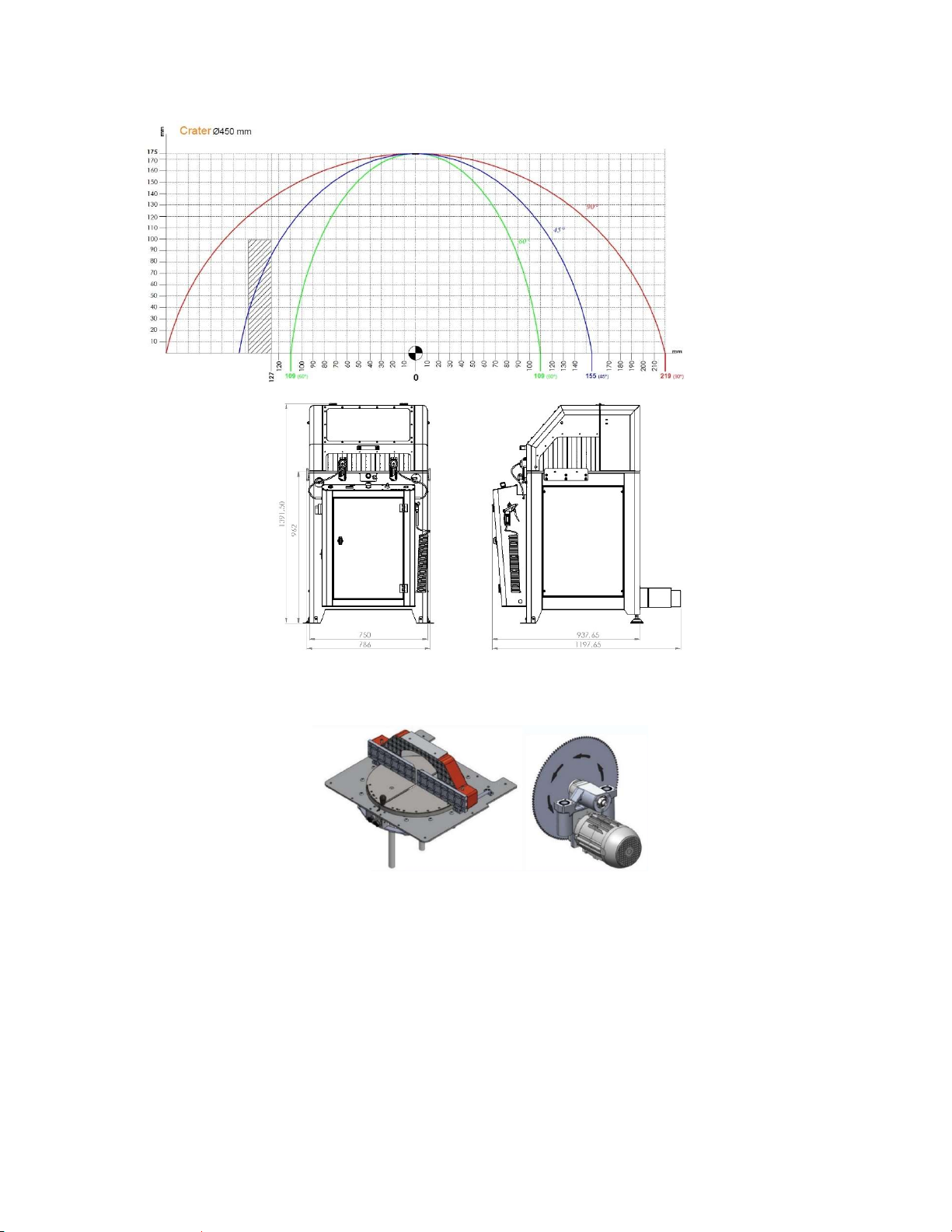
2.2. TECHNICAL FEATURES
2.2 KW / 3 HP D=450 mm (18”)
d=30-32 mm 3000 rpm
6-8 Bar
(90-120 psi)
14 lt/min
80x96x137 cm
(31”x38”x54”)
225 kg
(495 lbs)
Top Guard
Control Panel
Electric and Pneumatic
Panel
5
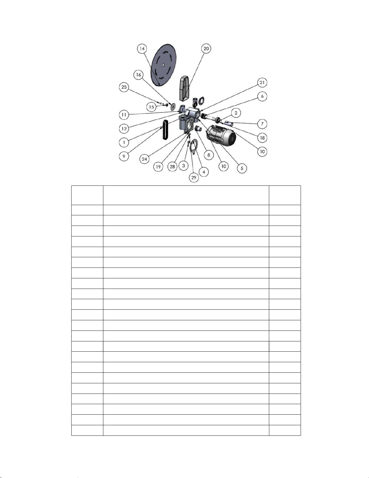
2.3. CUTTING DIAGRAM
2.4. OVERALL DIMENSIONS
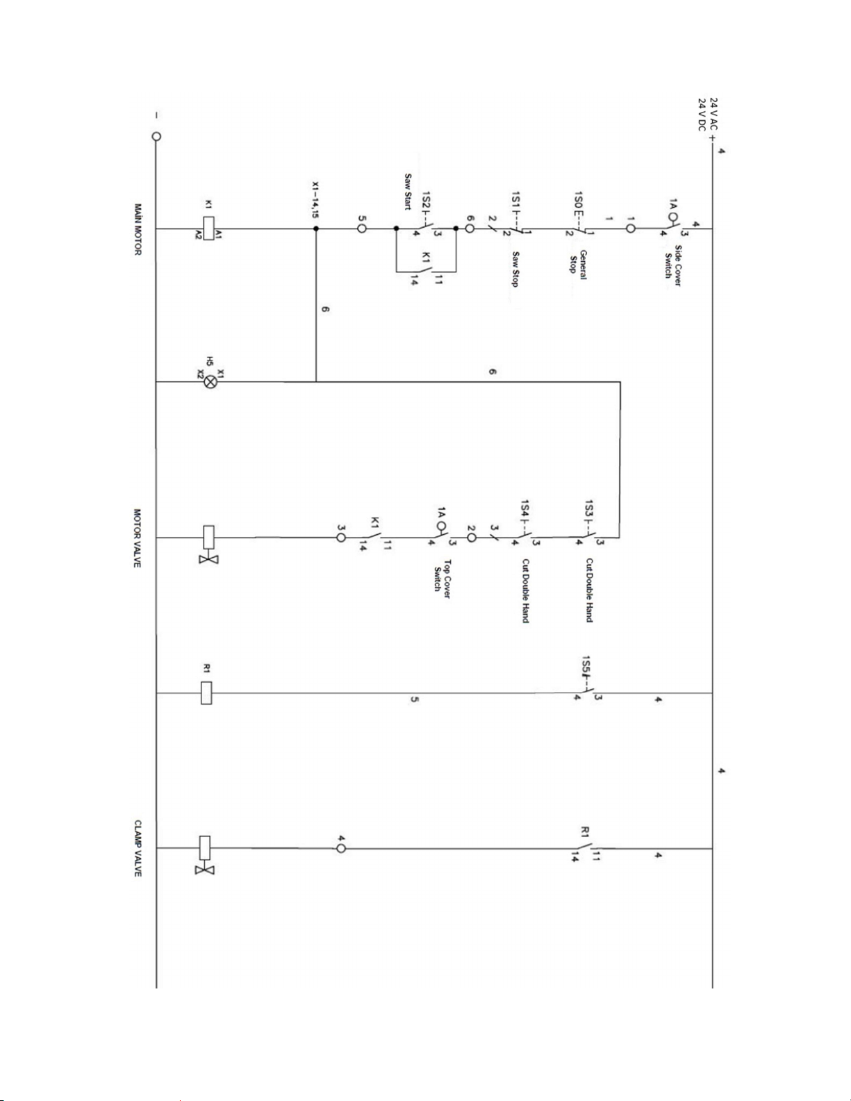
2.5. PARTS LIST AND TECHNICAL DRAWINGS
6
PART NO PART NAME QTY
1 CR-450_ MOTOR_GROUP_BED 1
2 6205_ZZ_BEARING 2
3 CR-450_MOTOR_TENSION_LOG 1
4 CR-450_MOTOR_TENSION_SHEET_METAL 1
5 CR-450_BEARING_COVER 2
6 CR-450_SAW_SHAFT 1
7 CR-450_SAW_SHAFT_PIPE 1
8 PJ_BELT_MOTOR_PULLEY (Q52x56x10KNL) 1
9 PJ-483_BELT 1
10 MOTOR_2.2KW_B14_3000RPM 1
11 LME-30-UU 4
12 SAW COUPLING 1
13 WASHER 30-32 mm 1
14 SAW BLADE Ø450 (18”) 1
15 REAR CLEVIS SPECIAL WASHER 1
16 CR-450_SAW_FLANGE 1
17 CR-450_MOTOR_PULLEY_WASHER 1
18 CR-450_SAW_SHAFT_NUT 1
19 CR-450_MOTOR_TENSION_BOLT_PRESSING_WASHER 1
20 CR-450_SAW_SAFETY 1
21 A_H.B_M6x20 6
22 A_H.B_M8x20 1

7
23 INBUS_M6x50 1
24 INBUS_M8x35 4
25 INBUS_M10x30 1
26 SETSCREW_M4x2,5 2
27 NARROW_STRAIGHT_WASHER _M8 4
28 A.A_M6x40 1
29 INBUS_M6x16 2
30 NUT_M6 1
2.6. ELECTRIC AND PNEUMATIC CONTROL PANEL
The operator panel is located in front of the saw table. In case of any repair or maintenance the power has to be cut
off prior to acces of this electric panel. All electrical works have to be carried out by a qualified electrician.
Below the operator panel there is the pneuamtic panel, where also the coolant bin of the spray mist system is
located. Please make sure that you use proper coolant (water based) for your cutting process..
The control panel door has to be closed and locked during
operation. In case of service carried out for maintenance and
possible defects;
DISCONNECT POWER AND OMPRESSED AIR SUPPLY TO THE
SAW.
If the air pressure falls below 4 bars (60 psi), the saw blade will
not rise and pneumatic clamps will not work.
Bolt for Fixing of
Intermediate Angles
Release Pin-Setting
Locked Angles
Motor Start-Stop
Button
Cutting Button
Air Gun
Motor Emergency
Stop Button
Cutting Button

8
2.7. PNEUMATIC CIRCUIT SCHEME

9
2.8 ELECTRIC POWER SCHEME
10
3. SAFETY

11
3.1. SAFETY INFORMATION
The symbols shown hereunder are necessary to be read with special attention.
Not reading or observing of them may cause damage to the equipment or personal injury.
The IMPORTANT symbol above is one telling to apply special care and to be careful at carrying out the specified
operation.
The CAUTION! symbol above warns you against specific dangers and requires to read the text. Not observing
may cause damage to the equipment.
The above symbol DANGER WARNING, warns you against specific dangers and you have definitely to read
them. Negligence may cause damage to the equipment and bodily injury. Read the user’s manual carefully before
using the machine or carrying out maintenance works.
3.2. ACCIDENT PRECENTION
3.2.1. Our machines are manufactured in accordance with EN 60204–1 and EN 292–2 CE safety directives, which
cover national and international safety directives.
3.2.2. It is the task of the employer to warn his staff against risks, to train them on prevention of accident, to provide
for necessary safety equipment and devices for he operator’s safety.
3.2.3. Before starting to work with the machine, the operator should check the features of the machine, learn all
details of the machine’s operation.
3.2.4. Machine should be operated only by staff members, who have read and understood the contents of this
manual.
3.2.5. All directives, recommendations and general safety rules contained in this manual have to be observed fully.
The machine cannot be operated in any way for purposes other than those described herein. Otherwise, the
manufacturer shall not be deemed responsible for any damages or injuries. And such circumstances would
lead to the termination of the warranty.
3.3. GENERAL SAFETY INFORMATION
3.3.1. The power cable should be led in such a way that nobody can step on it or nothing can be placed on it.
Special care be taken regarding the inlet and outlet sockets.
3.3.2. If the power cable should be damage during operation, don’t touch and unplug it. Never use damaged power
cables.
3.3.3. Don’t overload machines for drilling and cutting. Your machine will operate more safely with power supply
in accordan CE with the stipulated values.
3.3.4. Don’t place your hands between parts in motion.
3.3.5. Use prtective eye glasses and ear plugs. Don’t wear oversize clothes and jewels. These can be caught by
moving.
3.3.6. Keep your working place always clean, dry and tidy for accident prevention and safe operation.
3.3.7. Use correct illumination for the safety of the operator. (ISO 8995-89 Standard The Lighting of Indoor Work
System)
3.3.8. Don’t leave anything on the machine.
3.3.9. Don’t use any materials other than those recommended by the monufacturer for cutting operations on the
machine.
3.3.10. Ensure that the work piece is clamped appropriately by the machine’s clamp or vice.
3.3.11. Ensure safe working position, always keep your balance.
3.3.12. Keep your machine always clean for safe operation. Follow the instructions at maintenance and replacement
of accessories. Check the plug and cable regularly. If damaged, let it replace by a qualified electrician. Keep
handles and grips free of any oil and grease.
3.3.13. Unplug first, before conducting and maintenance works.
3.3.14. Ensure that any keys or adjustment tools have been removed before operating the machine.
3.3.15. If you are required to operate the machine outside, use only appropriate extension cables.
IMPORTANT
CAUTION!
12
3.3.16. Repairs should be carried out by qualified technicians only. Otherwise, accidents amt occur.
3.3.17. Before starting a new operation, check the appropriate function of protective devices and tools, ensure that
they work properly. All conditions have to be fulfilled in order to ensure proper operation of your machine.
Damaged protective parts and equipment have to be replaced or repaired properly (by the monufacturer or
dealer).
3.3.18. Don’t use machines with improper functioning buttuons and switches.
3.3.19. Don’t keep flammable, combustive liquids and materials next to the machine and electric connections.
3.4. SAFETY SYMBOLS AND MEANINGS
Electric warnings.
Use protective goggles.
If main connection cable is
damaged during operation, do not
touch it and disconnect the main
plug from main socket.
Use protective earmuffs.
When machine is working, do not
make your hand close to saw blade.
Use protective gloves when
changing the saw blade.
Keep working environment clean,
dry and tidy.
Read operating instructions
carefully before using or
maintaining the machine.
4. TRANSPORT OF THE MACHINE
* The transport should be done by qualified personnel only.
4.1.1. The machine should be transported by lifting with proper equipment (not touching the ground during the
transport).
4.1.2. The machine is delivered wrapped in nylon and packet in carton box, unless other form of packing is agreed
upon with the customer.
4.1.3. For the weight and overall dimensions of the machine see Technical Features.
5. INSTALLATION OF THE MACHINE
The position of the machine should be at least 50 cm (20”) from the rear wall so that the protective top guard can
be fully opened to the rear and the machine maintenance activities can be carried out properly. For Left and Right
side surfaces, look at the Dimensions page for the distance that must be left between the wall and the machine.
5.1. PREPARATION
5.1.1. The overall dimensions of the machine are indicated on the Dimensions page. The surface on which the
machine is to be placed must be a solid flat surface and a floor to carry the weight of the machine.
5.1.2. CRATER All parts in cutting machines are ready for use by the manufacturer.
5.2. ELECTRICAL CONNECTION
5.2.1. The three-phase electrical wiring has to be done by a qualified electrician only.
5.2.2. Check your input power before supplying power to the machine.
5.2.3. Make the electrical socket connections to position 0 of MAIN SWITCH on the machine.
IMPORTANT
13
* The socket conn
ections have to be made by a qualified electrician,
the rotation direction of the saw blade has to b
e observed by starting
the machine. If the saw blade rotates in reverse direction, the socket
connections have to be checked and re-connected properly.
** I
f the direction of rotation of the saw blade is reverse, it is dangerous
for the operator and equipment. It causes the saw blade
teeth to break
and crack.
Saw Blade Rotation Direction
Connect the saw in accordance with the wiring scheme provided with the saw. Make sure that the saw blade
rotates in the correct direction. Follow the following procedure:
1. Press the motor start button to rotate the saw blade
2. Observe the direction of rotation of the saw blade.
3. The direction of rotation of the saw blade is indicated with an arrow on te machine table.
If, as a result of this application, you see that the saw blade rotates in reverse direction:
Electrical connection has to be corrected by a licensed electrician (usually switching 2 hot wires).
The direction of rotation of the saw blade should not be defined without testing.
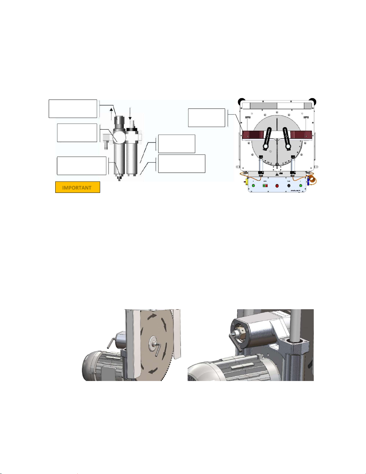
5.3. AIR PRESSURE ADJUSTMENT
5.3.1. Pull up the air conditioner adjustment knob.
a. The pressure increases when the setting button is turned clockwise.
b. The pressure decreases when the setting button is turned counterclockwise.
5.3.2. When you read the 6-8 bar pressure setting on the pressure gauge, lock the conditioner setting knob by
pushing it downwards.
5.3.3. Manufacturer recommended lubricant for conditioner: TELLLUS C 10, BP ENERGOL HLP 10, MOBILE DTE
LIGHT.
6. MACHINE SAFETY INFORMATION
6.1.1. It is forbidden to work by removing protective security equipment such as protective safety
covers and such.
6.1.2. Your machine must be operated with the voltage on the technical label. Make electrical
installation of your machine with a licensed electrician.
6.1.3. Qualified and competent personnel should be used for lifting, placing, electrical and
pneumatic maintenance work.
6.1.4. Routine maintenance work and scheduled maintenance must be carried out by authorized and qualified
personnel after the electrical and pneumatic power supplies are deactivated.
6.1.5. Before starting to work on the machine, make sure that the machine has been cleaned, tested and
maintained.
6.1.6. Routinely check the safety equipment, electrical power cable and moving parts. Do not operate the machine
don't starting it with a new one if you experience damage that can not fulfill safety functions or parts functions.
6.1.7. Never change the circle saw without interrupting the electrical power connection.
6.1.8. Do not place foreign objects in the operation area, do not place your hands between moving parts.
The safety informations is defined above. To prevent physical damage or equipment damage, please read
the safety information carefully and always keep the information in mind.
IMPORTANT
IMPORTANT
Saw Blade
Housing Guard
Hydro-Pneumatic
System Group
Cylinder
Hydraulic
Cylinder
Hydro-
Pneumatic
Tank Cylinder
14
7. OPERATION
Heavy duty upcut saws model CRATER are designed for cutting of non-ferrous metals (aluminum), vinyl and
wood. The operator adjusts the rising speed of the saw blade according to the material to cut using the knob on next
to the operator control panel on the lefty. Make sure to use proper saw blades with sharp carbide tips to achieve
optimum cutting results.
7.1. MITER CUTS
7.1.1. Do not try to cut prior to clamping the material using the toggle switch on the control panel.
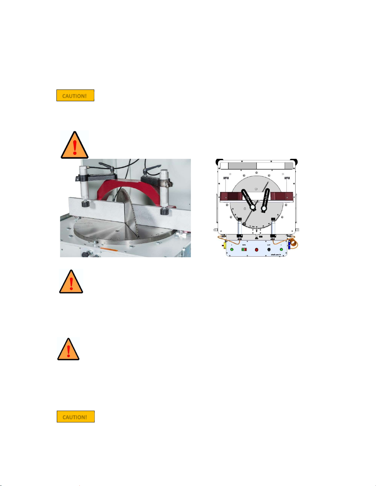
7.1.2. Your saw is equipped with twin vertical and horizontal pneumatic clamps. These can be easily adjusted to
the right & left, up & down to clamp your material to cut properly.
7.1.3. Once the toggle switch is engaged the piston cylinders move forward and clamp the workpiece.
Make sure that the clamp tips are outside the cutting area before starting the cutting process.
CORRECT WRONG
7.1.4. Avoid accidentally touching the buttons on the control board. If you face any danger
situation immediately press the Emergency Stop Button on the control panel.
7.1.5. Close the front door of the control panel and lock it with the key. (If the front door is open,
the motor will not operate for safety reasons).
NOTE: The front door and rear panel cover can only be opened when the machine is serviced and cleaned,
or when the saw blade is replaced. In such case switch the Main Switch to 0 to power off the saw.
Only after that open the front door and rear cover.
7.1.6. Loosen the M8 handles of the clamp cylinder brackets to enable clamp pistons adjustment (width and height)
according to the material size. Once adjusted tighten the clamp cylinders.
Before you fix the miter system after moving it, be sure to check the parallel of the miter with
"miter used for precise adjustment".
NOTE: Ensure that the Main Switch position is in the 0 position during this operation.
7.1.7. Set the cutting depth of the material to be cut according to the engraved angle degrees (15
0
-22.5
0
-30
0
-45
0
-
90
0
) on the side of the turntable. Pull the lock pin knob in the middle of the turntable to release and turn it.
Release the lock pin into the desired angle setting, which will then be locked. For any intermediate angles
release the lock pin know (by pulling it), turn the turntable to the desired angle, and fix the turntable at that
angle by tightening the bolt next to the lock pin knob.
NOTE: When performing miter cut operations on the saw, make sure that the clamps and
right-left back fences are outside the cutting area.
7.1.8. Set the length of the material to be cut to the desired unit of measure in meters/inch. Once the desired piece
size has been set, tighten the piece to fix the profile rest.
CAU
TION!
CAUTION!
15
7.1.9. Ensure that the pneumatic clamps tighten the piece using the toggle switch on the control panel.
7.1.10. Press the motor start button to rotate the saw blade.
7.1.11. Start the cutting action of the saw blade by pressing both (green) cutting start buttons simultanously. Keep
the butrtons pressed.
7.1.12. The circular saw blade will start to rise, make the cut, then move down to its starting position. This happens
also once you release the cutting start buttons the saw blade will move down.
7.1.13. Make sure to adjust the rising speed of the saw blade according to the material to cut.
7.1.14. Once the ut is finished release the clamp pistons via the toggle switch, and take out the cut piece.
NOTE: Set the air pressure between 6-8 bars. The manometer is read as air pressure bar. If the reading on
the pressure gauge is less than or equal to the desired pressure, turn the air pressure adjustment
switch to the right or left to adjust the pressure to 6-8 bar.
If your air pressure drops below 4 Bar, the saw blade will not move, and the clamps will not work until the air
pressure is returned to the desired level due to operational safety.
7.1.15. The air conditioner unit collects the water contained in the air system into the collection container in order
to avoid damage o the pneumatic system components. Periodically (on the working day) drain the water by
pressing or opening the button under the conditioning cylinder deposit to drain the collected water.
8.
SAFE INSTALLATION OF THE SAW BLADE
To remove the circular saw blade from the saw blade shaft, apply the following sequence.
8.1.1. Move the MAIN SWITCH on the machine to position 0. Using a phillips screwdriver, open the right-hand
cover.
8.1.2. Remove the M10 screw by turning with a 8 mm allen key (Hold the saw blade shaft at the opposite end with
another 8 mm allen key to prevent the shaft from turning).
8.1.3. Remove the 30x8x7mm washer, outer coupling and Saw Flange parts.
8.1.4. Carefully take out the saw blade.
Movable
Back Fence
Pressure
Adjustment Knob
Manometer
Air Pressure And
Water Discharge
Oil Storage
Oil Addition
Stopper
IMPORTANT

16
8.1.5. Fit the other parts (Washer and Saw Flange) in order, following the reversal of the operations on the shaft.
8.1.6. Tighten the M10 screw by turning it clockwise with an 8 mm Allen key (Hold the saw blade shaft at the
opposite end with another 8 mm allen key to prevent the shaft from turning).
8.1.7. The saw blade you use must be sharpened / changed at certain intervals depending on the type of
material being cut. When the cut workpiece is burrned at the end of cutting or when the cutting is
forced, sharpening / replacement of saw blade is necessary.
8.1.8. When replacing the saw blade with a new one, use the portion of the saw blade that corresponds to
the saw blade diameter. You can order new saw blades from ATech. The bore diameter is both 30
and 32mm.
9. SAFE INSTALLATION OF MOTOR BELT
Follow the instructions below to safely replace the motor belt of your saw:
9.1.1. Move the MAIN SWITCH on the machine to position 0. Open the front door with the key.
9.1.2. Remove the M6 screw by turning with a 5 mm allen key.
9.1.3. Remove the belt cover.
9.1.4. Loosen the M10 key-head bolt with the 10 mm keys.
CAUTION!
Ø450 mm (18”) Saw
Blade
Saw Blade Coupling
Saw Blade
Washer
Saw Flange
Washer
30x8x7
M10x20
Imbus Screw

17
9.1.5. Loosen the M8 screws by turning them clockwise with a 6 mm Allen key.
9.1.6. You can change the belt by loosening the motor block.
9.1.7. Once you have changed the belt, finish the process by following the procedures.
10. MAINTENANCE
10.1. ROUTINE CONTROLS, MAINTENANCE AND WORK STARTING
10.1.1. Make sure the table and all parts are clean and dry. Clean the table from the oil and dry it. Be especially
sure of the cleanliness and dryness of the handle.
10.1.2. Clean all surfaces of the machine from the sawdust, chips and foreign materials. Use glasses and glove to
protect yourself from harmful substances.
10.1.3. Check the saw blade against wear, bending, cracking and breakage before each use. Turn carefully to see
each tooth of the saw (after removing the saw protective housing). If the saw is damaged, change the saw.
10.1.4. Check the air pressure system pressure. If necessary, set the air pressure around 6-8 bar
10.1.5. Check the air pressure filters and the oil level in the conditioner. If you do not have enough oil, complete it.
Disconnect the electrical power connection and air pressure connections before doing all this.
10.2. METHOD OF HYDRO-PNEUMATIC CYLINDER AIR DISCHARGE AND ADDING OIL
10.2.1. METHOD OF HYDRO-PNEUMATIC CYLINDER AIR DISCHARGE
1. Revmove the 4 inbus head bolts, which connect the hydro-pneumatic cylinder to the system.
2. Remove the countersunk bolt which is connected to the saw bore of the shaft, from the top side of the
bore.
Loosen with 10 mm key

18
3. Remove the bolt, which connects the rising speed setting unit, located left from the control panel, to the
saw body..
4. Ake out the hydro-pneumatic cylinder.
5. Pull it out so that the shaft inside the hydro-pneumatic cylinder is in OPEN position (out position)
6. Connect/tighten the unit in the position as shown in the picture to the clamp.
7.
Open the oil drain / air discharge unit plug in the shape of the photo.
8. Press gently on the top of the oil discharge unit with a flat, blunt metal (for example 3 mm allen).
a. Foamy oil will come in the first place during pressing.
b. Continue this process slowly until the unfoamed oil comes out.
9. When the oil is foam free stop the process and wipe with a dry cloth. Replace hydro-pneumatic cylinder.
.2.2. OIL ADDING METHOD
It is possible that necessary oil level is reduced after the air discharge process. Since the amount of oil in the
system is reduced, the rising distance of the saw blade can be reduced. Here's what you need to do to get your saw
blade to reach the maximum height again. You need an oil pump for adding oil. However, if you do not have an oil
pump you can also do the following.
1. Follow the same steps until the first 6 items of hydro-pneumatic air discharge.
2. Remove the oil filler unit.
3. Add "HYDRO OIL HD 46" or equivalent oil to the system and close the oil filling unit.
4. Repeat steps 7 and 8 of the hydro-pneumatic cylinder air discharge method to discharge any possible air in the
system.
19
10.3.PNEUMATIC SPRAY MIST LUBRICATION SYSTEM MAINTENANCE
10.3.1. Open the front door of the machine, and take out the coolant receptacle.
10.3.2. The coolant prepared by opening the receptacle cover will be put into the receptacle provided that it is not
filled completely (The coolant should be water based)
10.3.3. Make sure that the hose on the cover is fully inserted into the receptacle and on the filter.
10.3.4. The cover will be tightly closed and the hose will be placed inside the machine, making sure not to bend it.
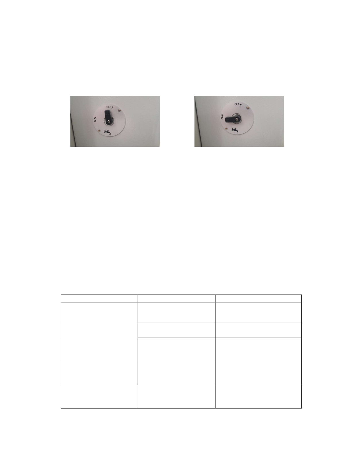
10.3.5. The valve on the side will be turned to “ON" position when coolant is required
Valve Closed
Valve Open
10.3.6. Coolant is sprayed onto the saw blade once the saw blade starts to rise, unless the valve is in OFF position.
10.4. WORK DAY END CARE
10.4.1. Disconnect the electrical power connections. (The Main Switch must remain in position 0.)
10.4.2. Clean all surfaces of the machine from the sawdust, chips and foreign materials. If cleaning of the protective
housing is necessary, remove the front cover and wear gloves to protect your hands from the cutting edges
of the saw. Use glasses to protect yourself from harmful substances.
10.4.3. If water and water based liquids are used during cutting operations, dry the machine with dry cloth at the
end of the work.
10.4.4. Apply a thin layer of oil to the plate to protect it from corrosion. If it is not to be used for a long time, lubricate
with a protective oil.
10.4.5. Avoid materials that damage the paintwork while cleaning the machine.
10.4.6. Lubricate both surfaces with machine oil or a protective oil to protect the saw from corrosion.
11. TROUBLESHOOTING
Our suggestions to get rid of immediate problems. If the fault can not be rectified or you encounter a fault other
than those listed below, please contact the technical service.
TROUBLES CAUSES REMEDY
Low surface quality (at
aluminum and similar materials);
Rough surface,
Large chip,
Not homogenous
surface,
Saw blade traces
visible
Not cooling the saw blade
surfaces
Lubricating the saw blade cutting
surfaces,
Using of cooling liquid.
Using of damaged or blunt saw
blade
Check the saw blade teeth. Replace
if necessary.
Saw blade moves to quick
The cutting speed is too high fort he
material. Decrease the cutting
speed.
Motor does not work (Start
button is pressed, not working) No power supply to the machine
Check the electric cable
connections. Check the electric
power sockets.
Motor is working but the
pneumatic clamp piston do not
work.
The air supply connections are
missing, or the air pressure is too
lowç
Check the air compressor
connections. Adjust the air pressure
between 6-8 Bar on the conditioner.

20
The saw blade rotates in reverse
direction.
The electric connection or the
power cable is wrong
Let the electric connections carry out
by a qualified electrician.
No lubrication.
It may be related to the oil
amount, oil fluidity or valve.
Check the oil level.
Observe the oil hose in the oil.
Open the valve.
Be sure to use the appropriate
oil.
Blow air into the end of the hose
inside the drum with an blow gun.
Lubrication is less. It may be related to the sprayer. Open the dimmer on the sprayer.
Table of contents
Other ATECH Saw manuals


 instruction manual")


