ATECH CRATER-06 A700 User manual


CONTENTS
1. GENERAL INFORMATION
1. Introduction
2. Supplier Info
2. MACHINE’S DESCRIPTION AND PURPOSE OF USE
1. Machine’s Description
2. Technical Features
3. Cutting Diagram
4. Overall Dimensions
5. Electric And Pneumatic Control Board
6. Part List and Technical Drawings
7. Pneumatic Circuit Scheme
8. Electric Power Scheme
9. Electric Circuit Scheme
3. SAFETY
1. Safety Information
2. Accident Prevention
3. General Safety Information
4. Safety Symbols And Meanings
4. TRANSPORT OF THE MACHINE
5. INSTALLATION OF THE MACHINE
1. Preparation
2. Instructions About Safe Connection Of The Machine To The Power Source
3. Air Pressure Setting
6. MACHINE SAFETY DATA
7. OPERATION
1. Miter Cuts
8. SAFE INSTALLATION OF THE SAW BLADE
9. SAFETY INSTALLATION OF THE BELT
10.MAINTENANCE
1. Routine Controls, Maintenance And Work Starting
2. Method Of Hydraucheck Air Reception And Oil Complementation
1

1. Method Of Hydraucheck Air Reception
2. Oil Completion Method
3. Spray Mist System Maintenance
4. Work Day End Care
11. TROUBLESHOOTING GUIDE
12. COMPONENTS
1. Electric Components
2. Hydraulic-Pneumatic Components
2

1. GENERAL INFORMATION
1.1. Introduction
The user’s manual given by the manufacturer contains information about the machine parts. Each machine
operator should read these instructions carefully, and the machine should be operated after fully understanding
them.
Safe and efficient use of the machine for long term depends on understanding and following the
instructions contained in this manual. The technical drawings and details contained in this manual constitute a
guide for the operator.
1.2. Supplier Info
ATECH MACHINE, INC.
8539 Ziggy Lane
Gaithersburg, MD 20877
Ph.: 240-505-1967
ATechMachinery.com
info@ATechMachinery.com
*In case of any technical problem please contact your nearest ATECH dealer or ATECH head office
through the above mentioned phone, fax or e-mail address.
*Technical labels with the model description of the machine are fixed onto the front side of each machine.
*The machine serial number, engine values, air pressure, air consumption and production date are printed
on the technical label.
2. MACHINE’S DESCRIPTION AND TECHNICAL FEATURES
2.1. Machine’s Description
PVC, Aluminum and wooden profiles are cutting machines with circular saw cutting in series at the desired
angles. The operator adjusts the cutting progress (manually from the cutting speed setting (see. Figure 1)) of the
saw according to the type and size of the material.
➢The machine is designed according to the CE regulations.
➢15ᵒ- 22,5ᵒ- 30ᵒ- 45ᵒ- 90ᵒthe angles with spring set, free cutting can be done at other intermediate
degrees.
➢It is possible to adjust the cutting speed progress precisely according to the material type.
➢During the cutting process, if the upper casing cover is opened, the saw don't cutting at the in terms of
safety and returns to the starting position.
➢After cutting is completed, the saw from the last point automatically returns to the starting point.
Please mention the below mentioned data in all your correspondence regarding the machine with the
manufacturer and/or your ATECH dealer.
•Machine model
STANDARD ACCESSORIES
•Ø700 / Ø760 mm Saw Blade
•Air gun
•2 Vertical Pneumatic Clamp Pistons
•1 Horizontal Pneumatic Clamp Piston
•Pneumatic Spray Mist Lubrication System
•Automatic opening of Top Guard
OPTIONAL ACCESSORIES
•Conveyor
•1 Qty. Horizontal Pneumatic Cylinder
•Chip Collector Manifold
3

•Machine’s serial number
•Voltage and frequency
•Name of dealer where machine was purchased
•Date of purchase
•Description of the machine fault
•Average daily operation period
!
Figure 1 : Hydro-Pneumatic Cylinder Saw Blade Rising Speed Adjustment
2.2. Technical Features
2.3. Cutting Diagram
4 KW / 5.5 HP
D=700 / 760
mm
d=38 mm
2000 rpm
6-8 Bar
150 lt/min
134 x 152 x 170 cm
(53”x60”x67”)
660 kg
(1,452
lbs)
4
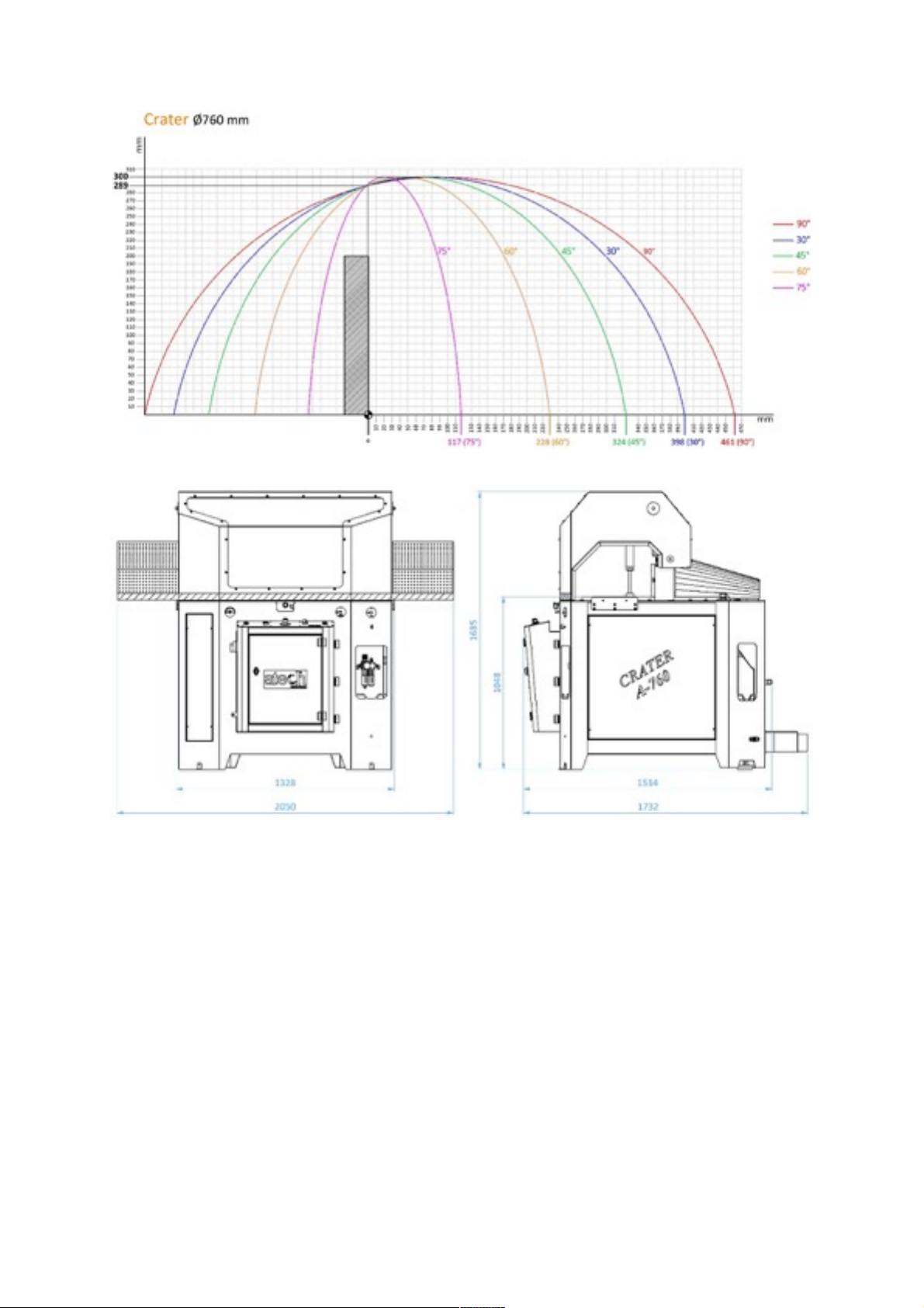
2.4. Overall Dimensions
2.5. Electric And Pneumatic Control Board
There is an electrical panel at the top, the energy must be turned off by the authorized electrician and should
be checked with the diagram on the cover in case of a problem.
In the lower part there is a pneumatic panel.
There is an irrigation canister behind the chassis. It must be opened by authorized personnel and filled with
suitable oil. The oil to be used must be water thick, the system is not suitable for throwing thick oil.
The panel door must be closed and locked during operation. In the service work carried out for maintenance
and possible defects;
CLOSE ELECTRICAL AND PNEUMATIC POWER RESOURCES.
If the air pressure falls below 4 bars, the movement of the saw and the movement of the pneumatic
vice can not be achieved.
2.6. Part List and Technical Drawings
5

No
Şekil / Figure
Adı / Name
Adet /
QTY
Parça Kodu / Code
1
Ø700 / Ø760 Saw
1
CRA70/76-02-0001
2
4 kW Motor
1
CRA70/76-04-0002
3
Motor Connection
Block
1
CRA70/76-02-0003
4
Belt Pulley
Protection Part
1
CRA70/76-02-0004
5
Motor Tensioner
Sheet Metal
1
CRA70/76-02-0005
6
Motor Tensioner Bolt
Print Washer
1
CRA70/76-02-0006
7
Motor Tensioner Part
1
CRA70/76-02-0007
8
Belt
1
CRA70/76-02-0008
9
Saw Shaft
1
CRA70/76-02-0009
6
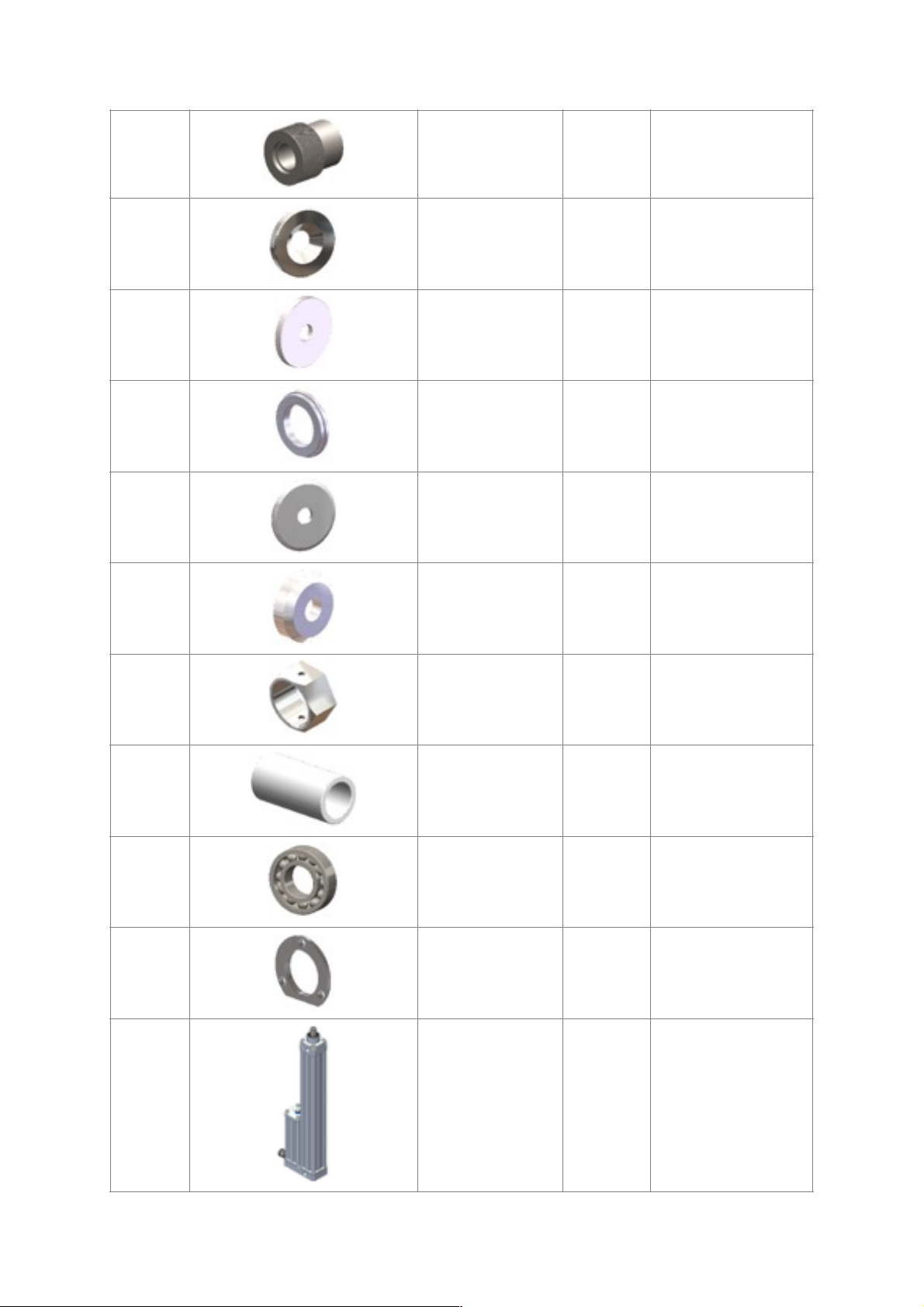
10
Motor Pulley
1
CRA70/76-02-0010
11
Motor Pulley Washer
1
CRA70/76-02-0011
12
Coupling
1
CRA70/76-02-0012
13
Washer (38-40mm)
1
CRA70/76-02-0013
14
Saw Flange
1
CRA70/76-02-0014
15
Saw Washer
1
CRA70/76-02-0015
16
Saw Shaft Nut
1
CRA70/76-02-0016
17
Saw Shaft Pipe
1
CRA70/76-02-0017
18
6207 ZZ Bearing
3
CRA70/76-02-0018
19
Bearing Cover
2
CRA70/76-02-0019
20
Hydraucheck
1
CRA70/76-03-0020
7

21
Pneumatic Cylinder
1
CRA70/76-03-0021
22
Top Cover Lifting
Cylinder
2
CRA70/76-03-0022
23
Saw Casing Cover
1
CRA70/76-01-0023
24
Moving Front Miter
2
CRA70/76-02-0024
25
Vertical Clamping
Pneumatic Cylinder
2
CRA70/76-03-0025
26
Horizontal Clamping
Pneumatic Cylinder
2
CRA70/76-03-0026
27
Standard Degree
Plate Tightening
Mechanism
1
CRA70/76-02-0027
28
Manual Conveyor
1
CRA70/76-01-0028
29
Chip Absorption
Manifold
1
CRA70/76-01-0029
8
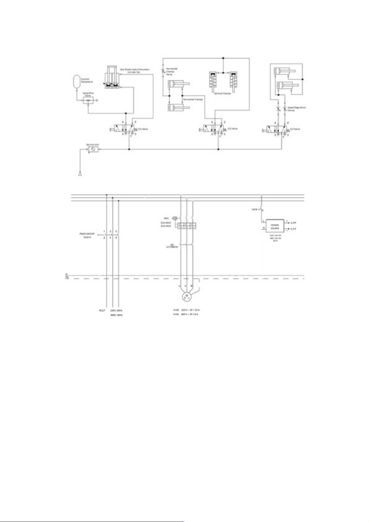
2.7. Pneumatic Circuit Scheme
2.8. Electric Power Scheme
!
2.9. Electric Circuit Scheme
9

!
3. SAFETY
3.1. Safety Information
The symbols shown hereunder are necessary to be read with special attention. Not reading or observing of
them may cause damage to the equipment or personal injury.
The IMPORTANT symbol above is one telling to apply special care and to be careful at carrying out the
specified operation.
The CAUTION! symbol above warns you against specific dangers and requires to read the text. Not
observing may cause damage to the equipment.
The above symbol DANGER WARNING, warns you against specific dangers and you have definitely to read
them. Negligence may cause damage to the equipment and bodily injury. Read the user’s manual carefully
before using the machine or carrying out maintenance works.
3.2.Accident Prevention
3.2.1. Our machines are manufactured in accordance with EN 60204–1 and EN 292–2 CE safety
directives, which cover national and international safety directives.
3.2.2. It is the task of the employer to warn his staff against risks, to train them on prevention of
accident, to provide for necessary safety equipment and devices for he operator’s safety.
3.2.3.Before starting to work with the machine, the operator should check the features of the machine, learn all
details of the machine’s operation.
10
3.2.4.Machine should be operated only by staff members, who have read and understood the contents of this
manual.
3.2.5.All directives, recommendations and general safety rules contained in this manual have to be observed
fully. The machine cannot be operated in any way for purposes other than those described herein.
Otherwise, the manufacturer shall not be deemed responsible for any damages or injuries. And such
circumstances would lead to the termination of the warranty.
3.3. General Safety Information
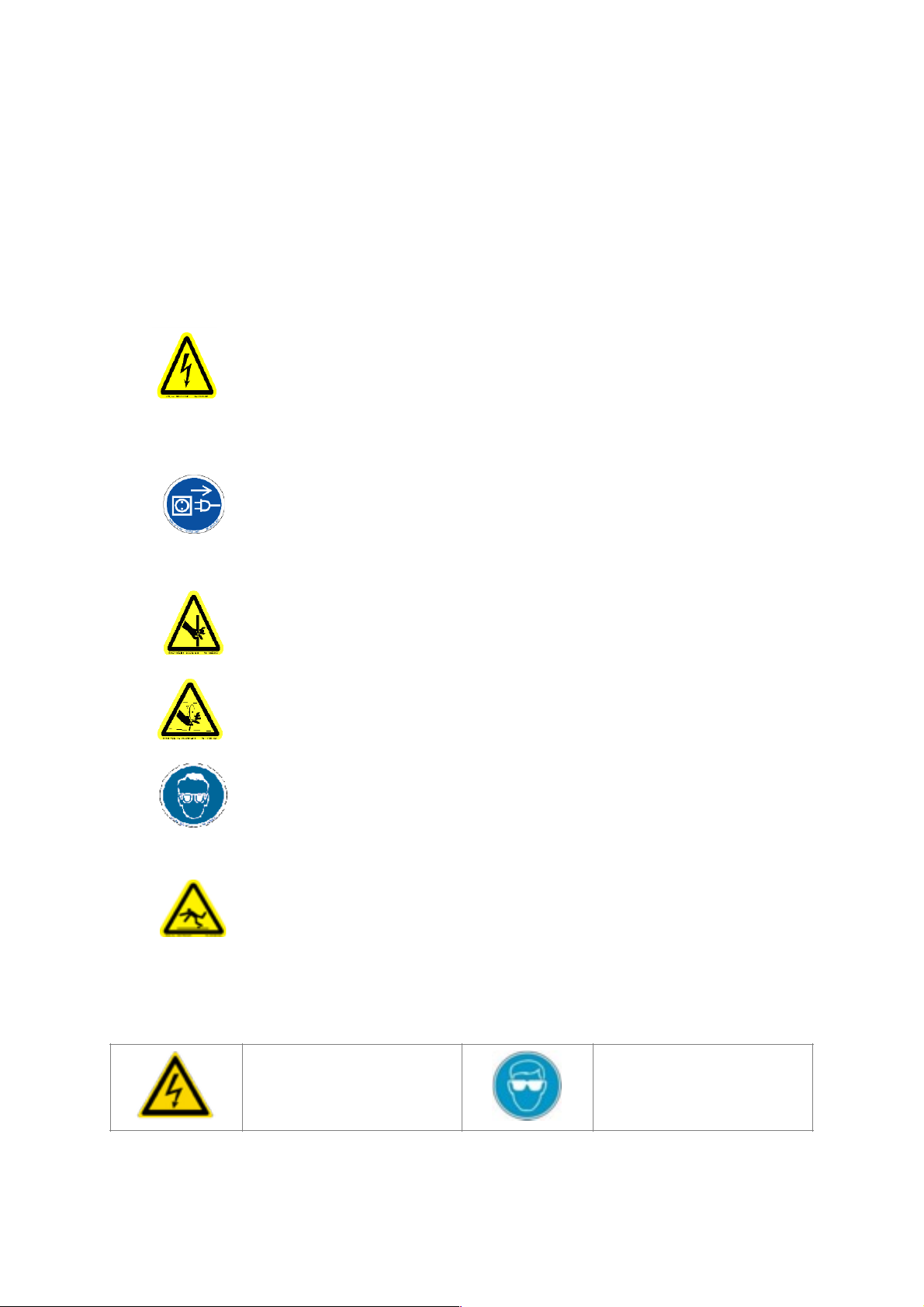
3.4. Safety Symbols And Meanings
1. The power cable should be led in such a way that nobody can step on it or
nothing can be placed on it. Special care be taken regarding the inlet and
outlet sockets.
2. If the power cable should be damage during operation, don’t touch and
unplug it. Never use damaged power cables.
3. Don’t overload machines for drilling and cutting. Your machine will operate
more safely with power supply in accordan CE with the stipulated values.
4. Don’t place your hands between parts in motion.
5. Use prtective eye glasses and ear plugs. Don’t wear oversize clothes and
jewels. These can be caught by moving.
6. Keep your working place always clean, dry and tidy for accident prevention
and safe operation.
7. Use correct illumination for the safety of the operator. (ISO 8995-89
Standard The Lighting of Indoor Work System)
8. Don’t leave anything on the machine.
9. Don’t use any materials other than those recommended by the
monufacturer for cutting operations on the machine.
10. Ensure that the work piece is clamped appropriately by the machine’s
clamp or vice.
11. Ensure safe working position, always keep your balance.
12. Keep your machine always clean for safe operation. Follow the instructions
at maintenance and replacement of accessories. Check the plug and cable
regularly. If damaged, let it replace by a qualified electrician. Keep handles
and grips free of any oil and grease.
13. Unplug first, before conducting and maintenance works.
14. Ensure that any keys or adjustment tools have been removed before
operating the machine.
15. If you are required to operate the machine outside, use only appropriate
extension cables.
16. Repairs should be carried out by qualified technicians only. Otherwise,
accidents amt occur.
17. Before starting a new operation, check the appropriate function of
protective devices and tools, ensure that they work properly. All conditions
have to be fulfilled in order to ensure proper operation of your machine.
Damaged protective parts and equipment have to be replaced or repaired
properly (by the monufacturer or dealer).
18. Don’t use machines with improper functioning buttuons and switches.
19. Don’t keep flammable, combustive liquids and materials next to the
machine and electric connections.
Electric warnings.
Use protective goggles.
!
!
11

4. TRANSPORT OF THE MACHINE
*The transport should be done by qualified personnel only.
4.4.1.The machine should be transported by lifting with proper equipment (not touching the ground during the
transport).
4.4.2.Don’t lift the machine before ensuring that lifting devices or other equipment is placed properly under the
machine.
4.4.3.For the weight and dimensions of the machine, 2.2. Technical Features.
5. INSTALLATION OF YOUR MACHINE
The machine should be located at least 100 cm in front of the back wall. The machine is equipped with a
burr collection bag connector and power supply socket on the back side.
5.1. Preparation
5.1.1.The outer dimensions of the machine are stipulated in the dimensions page. The ground, where the
machine will be placed, should be even, solid enough to bear the weight of the machine.
5.1.2.At the double head automatic saw machine Crater all parts are delivered by the manufacturer ready for
use.
5.1.3. Do not make electrical connections without removing the bolt and stop connections used for the
detection of running systems before the machine is started and without wiping the protective oil layer in
working parts.
If main connection cable is
damaged during operation, do
not touch it and disconnect the
main plug from main socket.
Use protective earmuffs.
When machine is working, do
not make your hand close to saw
blade.
Use protective gloves when
changing the saw.
Keep working environment
clean, dry and tidy.
Read operating instructions
carefully before using or
maintaining the machine.
!
!
!
!
!
!
12

5.2. Instructions For Safe Connection Of The Machine To The Power Source
5.2.1.The three-phase electrical cable socket must have five inputs to the cable on the machine.
5.2.2.Use a connection cable sockets in accordance with the CE Safety Directives.
5.2.3.Check the inlet power supply before powering the machine.
The socket connections have to be made by a qualified electrician, the rotation direction of the saw
blade has to be observed by starting the machine. If the saw blade rotates in reverse direction, the socket
connections have to be checked and re-connected properly. If the direction of rotation of the saw blade is
reversed, it is dangerous to Operator and equipment. It causes the saw teeth to break and cracks.
Plug the machine's electrical power socket into the previously prepared 3-phase socket socket to follow the
saw-turn direction and follow the following procedures:
1. Press the motor start button to rotate the saw.
2. Observe the direction of rotation of the saw.
3. The direction of rotation of the saw is available on the turn direction label on the table.
If the saw blade rotates in reverse direction: The electric socket connections have to be checked and
corrected by a qualified electrician. The direction of rotation of the saw must not be run without testing.
5.3. Air Pressure Setting
For the pneumatic system to operate properly, the air pressure must be 6-8 bars. Do not operate at lower
pressures than 6 bars. Read the manometer on the conditioner to calibrate and check the air pressure.
!!!!!!!!Follow the steps below for air pressure settings.
5.3.1.Pull up the conditioner adjustment knob.
5.3.2.The pressure increases when the knob is turned clockwise, while the pressure decreases when it is turned
counter- clockwise.
5.3.3.When you read the 6-8 Bar pressure setting on the pressure gauge, lock the conditioner setting knob.
5.3.4. The conditioner unit accumulates the water contained in the air system into the collection container so
as not to damage the pneumatic system components. Automatically removes water collected when air
is supplied to the machine.
5.3.5.The oil recommended by the manufacturer in the conditioner is TELLUS C 10 / BP ENERGOL HLP 10 /
MOBIL DTE LIGHT / PETROL OFFICE SPINDURA 10.
6. MACHINE SAFETY DATA
6.6.1. It is not allowed to operate the machine with the protective cover and other
protective equipment removed.
6.6.2. Your machine must be operated with the voltage on the technical label. Let the
electric installation of your machine carry out by a qualified electrician only.
Grounding must be done. There will be irregularities in machine operation if
grounding is not done properly.
6.6.3. Lifting, installation, electric, pneumatic maintenance of the machine should be
carried out by qualified personnel only.
13

6.6.4.Routine maintenance and scheduled maintenance should be carried out by qualified personnel after
unplugging the machine and disconnecting the air supply first.
6.6.5.Ensure that the machine has been cleaned, tested and maintenance before starting to operate.
6.6.6.Check the safety devices, power cable and moving parts regularly. Don’t operate the machine before
having replaced defective safety devices or faulty parts
6.6.7.Never replace the circular saw without disconnecting the air and the electrical and pneumatic power
connection.
6.6.8.Keep foreign materials away from the working area of the machine, keep away from the machine’s moving
parts.
The saw blade continues its rotation for a while after switching off the motor.
Don’t use the machine for purposes other than it has been designed for (cutting of iron and
other ferrous materials).
The safety data have been defined above. In order to prevent physical damage or
damage to the equipment, please read the safety information carefully and keep the
manual always in an easy accessible place.
If the top cover is open, the engine will not start in terms of worker safety.
7.OPERATION
CRATER Undercutting cutters cut products made from Aluminum, Wood and hard plastic materials which are
not ferrous alloy. The operator adjusts the cutting progress of the saw according to the type and size of the
material. (Manual) The inner and outer sharp edges of the circular saw allow you to obtain a smooth surface at
high quality.
7.1. Angled Cutting On The Plate
7.1.1. Do not try to cut the parts / materials that you want to cut before tighten the clamps on the machine.
7.1.2. The vices on the machine are in vertical or horizontal position. The pneumatic clamps can be easily
adjusted to the material.
7.1.3. The clamp piston moves in the pneumatic clamps.
During the cutting process, the clamping lugs of the clamps must be outside the work area of the
circular sawing.
14

7.1.4. Avoid touching the buttons on the clipboard at random. If you are in danger during cutting, press the
emergency stop button immediately to end cutting.
7.1.5. Close the front door on the chassis and control panel and lock it with the key. (If the chassis front cover
is open, the engine will not operate for safety reasons).
NOTE: The chassis front cover and rear panel cover can only be opened when the machine is serviced and
cleaned, or when the saw is replaced. At this time, turn the Main Switch's position to position 0 and turn
off the power, then open the front and back panel covers.
7.1.6. Set the cutting degree of the material to be cut according to the graduated scale (150- 22,50-300-450-900
etc) on the machine. Loosen the tab lock retaining screw by turning it clockwise to rotate the turntable.
Set the degree to which you want to work with the degree adjustment switch. Do the reverse operation of
loosening the turntable to secure it.
Do not use the horizontal clamp on the side where the saw rotates when cutting more than 45 °
in degrees.
NOTE: When performing graduated cutting operations on the machine, make sure that
the clamps and right-left miter frames are out of the operation area.
7.1.7.Set the length of the material to be cut to the desired unit of measure in meters. Once
the desired piece size has been set, tighten the piece to fix the profile rest.
7.1.8. Ensure that the vertical pneumatic vices tighten the piece using the vise button on the machine.
7.1.9. Press the motor start button to rotate the saw.
7.1.10.Start the cutting action of the saw by pressing both of the cut start buttons.
7.1.11.The circular saw will cut the fixed profile with the upward movement and continue to the closed
position until the cut start button is pressed again after the cutting operation is finished.
7.1.12.Cut the saw by manually adjusting the cutting speed adjustment valve according to the type and size of
the material to be sawed and cut the cutting process until the saw cuts down again.
7.1.13.Using the clamp button, remove the print on the clamps and remove the cut off piece.
CORRECT
WRONG
15
Pressure
Adjustment Knob
Manometer
Air Pressure and
Water Discharge
Oil Storage
Oil Additional
Stopper
Fixed Miter

Set the air pressure between 6-8 bars. The manometer is read as air pressure bar. If
the reading on the pressure gauge is less than or equal to the desired pressure, turn
the air pressure adjustment switch to the right or left to adjust the pressure to 6-8
bar. If your air pressure drops below 4 Bar, the saw movement on the machine and the
vices will not work until the air pressure is returned to the desired level due to
operational safety.
7.1.14.The conditioner unit collects the water contained in the air system into the collection container so as
not to damage the pneumatic system components. Periodically (on the working day) drain the water by
pressing or opening the button under the conditioning cylinder deposit to drain the collected water.
8. SAFE INSTALLATION OF THE SAW BLADE
To remove the circular saw blade from the saw mile, apply the following sequence.
8.8.1. Cut off the machine's electrical and air connection. Open the control board with the front cover lock on
the chassis, remove the side cover sheet metal. (Figure 2, 3)
8.8.2. Remove the saw casing cover sheet metal. (Figure 4)
8.8.3. Remove the M10 screw by turning with a 8 mm allen key (Hold the saw blade shaft at the opposite end
with a other 8 mm allen key and prevent so that the shaft turns). (Figure 5, 6)
8.8.4. Remove the 30x8x7mm washer and Saw Flange parts regularly. (Figure 7)
8.8.5. Carefully remove the saw.
8.8.6. Fit the saw you want to change on the shaft, making sure the direction of rotation is correct.
8.8.7. When replacing the saw with the new one, use the portion of the saw blade that corresponds to the
saw blade diameter. The outer diameter of the saw ring is two parts according to 38 and 40mm.
8.8.8. Fit the other parts (Washer and Saw Flange) in order, following the reversal of the operations on the
shaft.
8.8.9. Tighten the M10 screw by turning it clockwise with an 8 mm Allen key (Hold the saw blade shaft at the
opposite end with a other 8 mm allen key and prevent so that the shaft turns).
8.8.10.Install the saw cover. Close the chassis side cover plate and control board.
NOTE : The saw you use must be sharpened / changed at certain intervals depending on the type of
material being cut. When the cut workpiece is burned at the end of cutting or when the cutting is
forced, sharpening / changing operation is performed.
16
Saw Flange
Washer 30x8x7
Saw Washer
M10x30 Inbus
Screw
Ø700 / Ø760 mm Saw
Coupling

9. SAFE INSTALLATION OF THE BELT
Follow the instructions below to safely replace the CRATER A700/760 machine belt.
9.9.1.Remove the saw by performing the saw disassembly procedures.
9.9.2.Remove the saw guard assembly.
9.9.3.Remove the M6 screw by turning with a 5 mm allen key.
Figure 2 : Open The Control Board And The Side
Cover Plate.
Figure 3
Figure 4
Figure 5
Figure 6
Figure 7
17

9.9.4.Remove the belt cover.
9.9.5.Loosen the M10 key-head bolt with the 10 mm keys.
9.9.6.Loosen the M8 screws by turning them clockwise with a 6 mm Allen key.
9.9.7.You can change the belt by loosening the motor block.
9.9.8.Once you have changed the belt, finish the process by following the
procedures.
10. MAINTENANCE
1. Routine Controls, Maintenance And Work Starting
1.1. Make sure the table and all parts are clean and dry. Clean the table from the oil and dry it. Be
especially sure of the cleanliness and dryness of the handle.
1.2. Clean all surfaces of the machine from the sawdust, chips and foreign materials. Use glasses and glove
to protect yourself from harmful substances.
1.3. Check the saw blade against wear, bending, cracking and breakage before each use. Turn carefully to
see each tooth of the saw (after removing the saw protective housing). If the saw is damaged, change
the saw.
1.4. Check the air pressure system pressure. If necessary, set the air pressure around 6-8 bar.
1.5. Check the air pressure filters and the oil level in the conditioner. If you do not have enough oil, complete
it.
Disconnect the electrical power connection and air pressure connections before doing all this.
2. Method Of Hydro-Pneumatic Cylinder Air Reception And Oil Complementation
10.2.1. Method Of Hydro-Pneumatic Cylinder Air Reception
1. Remove 4 allen head bolts that connect hydro-pneumatic cylinder to the system.
2. Remove the countersunk head bolt from the top of the torso, which is connected to the hub of the machine.
3. Remove the nut connecting the speed setting (min-max) unit to the left of the front control panel.
4. Remove the hydro-pneumatic cylinder.
5. Pull out the shaft in the hydro-pneumatic cylinder to be in the ON (out) position.
6. In the position shown in the picture, the unit to the clamp so that the system is not damaged connect/tighten.
18
Loosen with 10

7. Open the oil drain / deaeration unit plug in the shape of the photo.
8. Press gently on the top of the oil discharge unit with a flat, blunt metal (for example 3 allen).
a. Foamy oil will come in the first place during the press.
b. Continue this process slowly until the unfoamed oil comes.
9. When the oil is froth free stop the process and wipe with a dry cloth. Replace the hydro-pneumatic cylinder.
10.2.2. Oil Completion Method
There is a possibility of a handicap after the air reception process. That's the output height of the saw.
Since the amount of oil in the system is reduced, the output distance of the saw can be reduced. Here's what
you need to do to get your saw to reach the maximum height again. Oil pressing tool is necessary operation for
oil pressing. However, if you do not have the necessary oil-press tool, you can also do the following.
1. Follow the same steps until the first 6 items of hydro-pneumatic cylinder air reception.
2. Remove the oil filler unit.
3. Add "HYDRO OIL HD 46" or equivalent oil to the system and close the oil filling unit.
4. Repeat steps 7 and 8 of the hydro-pneumatic cylinder air reception method to get any air that may form in
the system.
3. SPRAY MIST SYSTEM MAINTENANCE
3.1. The front cover of the machine will be opened and the drum at the bottom will be taken out.
3.2. The cooling oil prepared by opening the drum cover will be put into the drum provided that it is not filled
completely (The oil to be used should be close to the water flow, the system is not suitable for throwing
thick oil).
3.3. Make sure that the hose on the cover is fully inserted into the canister and on the filter.
3.4. The cover will be tightly closed and the hose will be placed inside the machine, taking care not to break
it.
19
This manual suits for next models
1
Table of contents
Other ATECH Saw manuals


