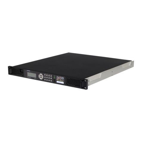
Ateme Kyrion CM5000 User manual

CM5000 - Modular
Contribution Encoder
users' manual

CM5000 users' manual UM-CM5000-FW1.1-REV1.0
2012-10-30
www.ateme.com Page ii
Table of Contents
1. Document Overview ........................................................................................................ 7
1.1. Document identification ......................................................................................... 7
1.2. Disclaimer ........................................................................................................... 7
1.3. Copyrights .......................................................................................................... 7
1.4. Precautions .......................................................................................................... 8
2. Product Overview ........................................................................................................... 9
2.1. Package Content ................................................................................................... 9
2.2. Front View ........................................................................................................ 10
2.3. Rear View ......................................................................................................... 11
2.4. Power Switch ..................................................................................................... 12
2.5. I/O Base Interfaces ............................................................................................. 13
2.6. Extended Interfaces ............................................................................................. 14
2.6.1. Extended L-Band Modulator Interfaces ........................................................ 15
2.6.2. Extended IF Modulator Interfaces ................................................................ 16
2.6.3. Extended AES Audio Interfaces .................................................................. 18
2.6.4. Extended Analog Audio Interfaces .............................................................. 19
2.7. Serial Number .................................................................................................... 20
2.8. Ventilation ......................................................................................................... 21
3. Installation ................................................................................................................... 22
3.1. Hardware setup .................................................................................................. 22
3.2. Quick start ......................................................................................................... 23
4. User's Interfaces ............................................................................................................ 24
4.1. Three configuration tools ..................................................................................... 24
4.2. Front Panel ........................................................................................................ 24
4.2.1. Status LED ............................................................................................. 24
4.2.2. LCD ...................................................................................................... 25
4.2.3. TFT ....................................................................................................... 25
4.2.4. Keypad ................................................................................................... 25
4.2.5. Menu ..................................................................................................... 25
4.3. Web GUI .......................................................................................................... 29
4.3.1. Access setup ............................................................................................ 29
4.3.2. Web Based GUI Overview ......................................................................... 30
4.3.3. Status Tab ............................................................................................... 31
4.3.4. Channel Tab ............................................................................................ 31
4.3.5. System Tab ............................................................................................. 33
5. Settings ....................................................................................................................... 35
5.1. Preset Settings .................................................................................................... 35
5.1.1. Global .................................................................................................... 35
5.1.2. TS ......................................................................................................... 35
5.1.3. Output ASI ............................................................................................. 37
5.1.4. Output DVB-S/S2/DSNG ........................................................................... 37
5.1.5. Output IP ................................................................................................ 38
5.1.6. Video ..................................................................................................... 38
5.1.7. Audio ..................................................................................................... 41
5.1.8. Data ....................................................................................................... 42
5.2. System Settings .................................................................................................. 44
5.2.1. System - Miscellaneous ............................................................................. 44
5.2.2. System - Time ......................................................................................... 44
5.2.3. System - Network Interface ........................................................................ 44
5.2.4. System - Network VLAN .......................................................................... 45
5.2.5. System - Network Route ............................................................................ 45

CM5000 users' manual UM-CM5000-FW1.1-REV1.0
2012-10-30
www.ateme.com Page iii
5.2.6. System - Alarms ...................................................................................... 45
5.2.7. System - Logs ......................................................................................... 46
5.2.8. System - SNMP Trap Target ...................................................................... 46
5.2.9. System - SNMP Password ......................................................................... 46
5.2.10. System - Statmux ................................................................................... 46
6. Specific Operations ....................................................................................................... 48
6.1. Installing License ................................................................................................ 48
6.2. Firmware management ......................................................................................... 48
6.3. Recovery ........................................................................................................... 49
A. Appendix .................................................................................................................... 51
A.1. Product's specification ......................................................................................... 51
A.2. Warranty .......................................................................................................... 61
A.3. Normative Reference .......................................................................................... 62
A.4. Glossary ........................................................................................................... 63
A.5. Support and Ressources ...................................................................................... 64

CM5000 users' manual UM-CM5000-FW1.1-REV1.0
2012-10-30
www.ateme.com Page iv
List of Figures
2.1. Front View Interface ................................................................................................... 10
2.2. Rear View Interface .................................................................................................... 11
2.3. Power Switch ............................................................................................................. 12
2.4. I/O Base Interface ....................................................................................................... 13
2.5. Extended L-Band Modulator Interfaces ........................................................................... 15
2.6. Extended IF Modulator Interfaces .................................................................................. 16
2.7. Extended AES Audio Interfaces .................................................................................... 18
2.8. Extended Analog Audio Interfaces ................................................................................. 19
2.9. Serial Number and Production Code Markings ................................................................. 20
2.10. Cool air intakes on the front panel ............................................................................... 21
2.11. Warm air outputs on the rear panel .............................................................................. 21
4.1. Front Panel sub-elements' identification .......................................................................... 24
4.2. Log into the Web Server .............................................................................................. 30
4.3. Web Based Interface ................................................................................................... 31
4.4. WEB Based Interface - Status Tab ................................................................................. 31
4.5. WEB Based Interface - Channel Tab .............................................................................. 32
4.6. WEB Based Interface - System Tab ............................................................................... 33
4.7. Simple setting edition .................................................................................................. 33
4.8. Table setting edition .................................................................................................... 33

CM5000 users' manual UM-CM5000-FW1.1-REV1.0
2012-10-30
www.ateme.com Page v
List of Tables
1.1. Document Identification ................................................................................................ 7
2.1. Front View Interface ................................................................................................... 10
2.2. Rear View Interface .................................................................................................... 11
2.3. Power Switch ............................................................................................................. 12
2.4. I/O Base Interface ....................................................................................................... 13
2.5. Extended L-Band Modulator Interfaces ........................................................................... 15
2.6. Extended IF Modulator Interfaces .................................................................................. 16
2.7. Extended AES Audio Interfaces .................................................................................... 18
2.8. Extended Analog Audio Interfaces ................................................................................. 19
4.1. Status LED ................................................................................................................ 25
4.2. Front Panel Menu - Main ............................................................................................. 25
4.3. Front Panel Menu - Service Modulator ........................................................................... 27
4.4. Front Panel Menu - Service Main .................................................................................. 27
4.5. WEB Based Interface - Channel Tab Settings .................................................................. 32
4.6. WEB Based Interface - System Tab Settings .................................................................... 34
5.1. Global ...................................................................................................................... 35
5.2. TS ............................................................................................................................ 35
5.3. DVB compliance ........................................................................................................ 36
5.4. Carrier ID ................................................................................................................. 36
5.5. ATSC ....................................................................................................................... 36
5.6. Output ASI ................................................................................................................ 37
5.7. Output DVB-S/S2/DSNG ............................................................................................. 37
5.8. Output IP .................................................................................................................. 38
5.9. Video ....................................................................................................................... 38
5.10. MPEG-4 AVC .......................................................................................................... 39
5.11. MPEG-4 AVC-I ........................................................................................................ 40
5.12. MPEG-2 .................................................................................................................. 40
5.13. Audio ...................................................................................................................... 41
5.14. MPEG Layer2 .......................................................................................................... 42
5.15. AAC ....................................................................................................................... 42
5.16. Dolby Digital ........................................................................................................... 42
5.17. Data ........................................................................................................................ 42
5.18. Teletext and VBI teletext descriptor ............................................................................. 43
5.19. Teletext and VBI teletext filter .................................................................................... 43
5.20. VBI ........................................................................................................................ 43
5.21. DVB Subtitles .......................................................................................................... 43
5.22. DVB Subtitles descriptor ............................................................................................ 43
5.23. Miscellaneous ........................................................................................................... 44
5.24. Time ....................................................................................................................... 44
5.25. Interface .................................................................................................................. 44
5.26. VLAN ..................................................................................................................... 45
5.27. Route ...................................................................................................................... 45
5.28. Alarms .................................................................................................................... 45
5.29. Logs ....................................................................................................................... 46
5.30. Trap target ............................................................................................................... 46
5.31. Passwords ................................................................................................................ 46
5.32. Statmux ................................................................................................................... 46
A.1. Specification - Identification ........................................................................................ 51
A.2. Specification - Physical ............................................................................................... 51
A.3. Specification - Environmental and Power ....................................................................... 51
A.4. Specification - Certifications ........................................................................................ 51

CM5000 users' manual UM-CM5000-FW1.1-REV1.0
2012-10-30
www.ateme.com Page vi
A.5. Specification - Configuration and Management ................................................................ 51
A.6. Specification - Video Input .......................................................................................... 52
A.7. Specification - Audio Input .......................................................................................... 52
A.8. Specification - Data Input ............................................................................................ 53
A.9. Specification - Black Burst-3Level and ASI Synchronization .............................................. 53
A.10. Specification - Filter ................................................................................................. 53
A.11. Specification - Specification - Video Processing ............................................................. 54
A.12. Specification - Audio Processing ................................................................................. 55
A.13. Specification - Specification - Data Processing .............................................................. 55
A.14. Specification - Muxer ................................................................................................ 56
A.15. Specification - Output ............................................................................................... 56
A.16. Specification - L-Band or IF Modulator ........................................................................ 57
A.17. Specification - System ............................................................................................... 59
A.18. Normative reference .................................................................................................. 62
A.19. Glossary ................................................................................................................. 63

CM5000 users' manual UM-CM5000-FW1.1-REV1.0
2012-10-30
www.ateme.com Page 7
1. Document Overview
1.1. Document identification
Table 1.1. Document Identification
Title CM5000 - Modular Contribution Encoder - users' manual
Revision Number 1.0
Description Document for firmware release 1.1
Date of Issue 2012-10-30
Document Reference UM-CM5000-FW1.1-REV1.0
1.2. Disclaimer
The material in this document is for information only and subject to change without notice. While reason-
able efforts have been made in the preparation of this document to assure its accuracy, ATEME assumes
no liability resulting from errors or omissions in this document, or from the use of the information con-
tained herein. ATEME reserves the right to make changes or revisions in the product design or the product
manual without reservation and without obligation to notify any person of such revisions and changes.
1.3. Copyrights
Notice
The ATEME Kyrion(R) is not designed or intended to violate any other entity's copyright or other IP (In-
tellectual Property) rights. Each ATEME Kyrion(R) user may only use their ATEME Kyrion(R) in con-
junction with materials legally owned or licensed by such user, and only to the extent that such ownership
or license rights permit such use.
Copyright (c) 2011-2012 ATEME
These materials, ATEME products and all related documentation are protected by copyright and other
laws, international treaties and conventions. All rights, title and interest in the materials, ATEME products
and related documentation shall remain with ATEME and its licensors. All registered or unregistered
trademarks in these materials are the sole property of their respective owners. No part of this document or
related ATEME products may be reproduced in any form, or by any means without written authorization
of ATEME Corporation.
Thesematerialsareprovided"as-is."ATEMEmakesnowarranties,statedorimplied,asto,theinformation
containedherein.Inaddition,ATEMEmakesnostated or impliedwarrantiesofmerchantabilityor working
condition for a particular purpose or use with respect the information contained in these materials.

CM5000 users' manual UM-CM5000-FW1.1-REV1.0
2012-10-30
www.ateme.com Page 8
Inno event shallATEMEbeliablefor any indirect,special,consequentialorincidental damages, including,
but not limited to, lost profits or loss or damage to data arising from the use of these materials, even if
advised in advance of the possibility of such damages.
The glossary of this document is partially extracted from the Wikipedia encyclopedia: Copyright (c)
ATEME
Trademarks
ATEME, the ATEME logo, Kyrion(R) and the KYRION(R) logo are all trademarks or registered trade-
marks of ATEME Corporation. The Kyrion(R) clustering technology -as well as other technologies in-
cluded in Kyrion(R) - are protected by patents or pending patent applications in the U.S. and other coun-
tries. All other trademarks or registered trademarks are property of their respective owners.
1.4. Precautions
Only qualified persons are authorized to carry out maintenance on this device.
Read the Users' Manual carefully, and follow the correct procedure when setting up the device.
Do not open your Kyrion or attempt to disassemble or modify it, unless instructed by an ATEME repre-
sentative. To avoid any risk of electrical shock, fire, short-circuiting or dangerous emissions, never insert
any metallic object into the enclosure. Your Kyrion contains no user-serviceable parts. If it appears to be
malfunctioning, have it inspected by a qualified ATEME Technical Support representative.
Never expose your device to rain, use it near water, or in damp or wet conditions. Never place objects
containing liquids on the Kyrion, as they may spill into its openings; doing so increases the risk of electrical
shock, short-circuiting, fire or personal injury.
Basic electrical safety precautions should be followed to protect you from harm and the system from
damage:
• Be aware of where the On/Off power switch is situated on the chassis; as well as the rack's emergency
power off- switch. Check also where the disconnection switch or electrical outlet is located.
• Do not work alone when working with high voltage components.
• Powershouldalwaysbedisconnectedfrom the system before opening it. When disconnecting the power,
you should first power down the system and unplug the power cords of the power supply.
• Only the provided power supply cord must be use to power the Kyrion. This power supply cord includes
a grounding plug and it must be plugged into a grounded electrical outlet. If you should use a different
power supply cord, make sure it is compatible with your locale electrical power supply.

CM5000 users' manual UM-CM5000-FW1.1-REV1.0
2012-10-30
www.ateme.com Page 9
2. Product Overview
2.1. Package Content
Before continuing, please check the content of the product package. This product package should contain
the following items:
• One (1) Kyrion(R) CM5000,
• One (1) Power Cord,
• One (1) CD ROM,
• This User's Manual.
If anything is missing, please contact your place of purchase.

CM5000 users' manual UM-CM5000-FW1.1-REV1.0
2012-10-30
www.ateme.com Page 10
2.2. Front View
Next picture describes the front interface of the Kyrion(R) CM5000.
Figure 2.1. Front View Interface
Table 2.1. Front View Interface
FP Front Panel
A Air Intakes
Front Panel Interfaces FP are described in Section 4.2, “ Front Panel ”
Ventilation using Air Intakes A is described in Section 2.8, “ Ventilation ”

CM5000 users' manual UM-CM5000-FW1.1-REV1.0
2012-10-30
www.ateme.com Page 11
2.3. Rear View
Next picture describes the generic rear interfaces of Kyrion(R) Encoders.
Depending on your exact model and the options purchased, the extended slots may contain additional
connectors which will be described in the next paragraphs.
Figure 2.2. Rear View Interface
Table 2.2. Rear View Interface
B I/O Base Interfaces
X I/O Extended X Interfaces
VA I/O Extended A Interfaces
VB I/O Extended B Interfaces
SN Serial Number and Product Code

CM5000 users' manual UM-CM5000-FW1.1-REV1.0
2012-10-30
www.ateme.com Page 12
2.4. Power Switch
Next figure describes the location of the Power switch of the Kyrion(R) CM5000.
Figure 2.3. Power Switch
Table 2.3. Power Switch
P1 Power Switch Use this switch to turn ON the unit. Switch it
back to the original position to turn OFF the unit.

CM5000 users' manual UM-CM5000-FW1.1-REV1.0
2012-10-30
www.ateme.com Page 13
2.5. I/O Base Interfaces
Next figure describes the I/O Base interfaces of the Kyrion(R) CM5000.
Figure 2.4. I/O Base Interface
Table 2.4. I/O Base Interface
B1 AC Inlet (~AC) Connect the provided cable to this inlet.
The Kyrion(R) auto detects AC voltage.
B2 MGT Ether-
net Connector
This dedicated Ethernet connector allows adminis-
tration of the Kyrion(R) via the Web or SNMP. This
interface is a 1000Base-T Ethernet port (1Gbps).
B3 STREAM Ether-
net Connector 1 This Ethernet connector is dedicated for streaming encoded
video over IP. This interface is a Gigabit Ethernet port (1Gbps).
B4 STREAM Ether-
net Connector 2 Same as [B3].
B5 Synchro In Connector This BNC Connector is dedicated to synchronize the encoder.
B6 ASI In Connector This BNC Connector is dedicated to input ASI stream.
B7 ALARM Connector This DB9 connector is dedicated to
input and output discrete signals.

CM5000 users' manual UM-CM5000-FW1.1-REV1.0
2012-10-30
www.ateme.com Page 14
2.6. Extended Interfaces
Depending of the hardware options that you purchased, some of the next interfaces may be accessible on
I/O Extended Interfaces ([X], [VA], [VB]).

CM5000 users' manual UM-CM5000-FW1.1-REV1.0
2012-10-30
www.ateme.com Page 15
2.6.1. Extended L-Band Modulator Interfaces
Next figure describes the Extended L-Band Modulator interfaces of the Kyrion(R) CM5000.
Figure 2.5. Extended L-Band Modulator Interfaces
Table 2.5. Extended L-Band Modulator Interfaces
XLB1 Encoder SDI IN Use this BNC connector to input the SDI video signal into the Encoder.
ALB1 Encoder ASI OUT Use this BNC connector to output the encoded bitstream. It
should be connected to the ASI input of the Modulator [LB3].
LB1 Modulator REF IN
Use this connector to input the external 10MHz reference
frequency used by the Modulator. The modulator can ei-
ther used this external reference frequency or a 10MHz in-
ternal reference frequency (selection trough GUI interface)
LB2 Modulator
REF OUT This connector outputs the 10MHz ref-
erence frequency used by the Modulator.
LB3 Modulator ASI IN Use this BNC connector to input the ASI
stream to be modulated by the Modulator.
LB4 Modulator
ASI MON This connector outputs a monitoring
copy of the ASI stream to be modulated.
LB5 Modulator L-
Band MAIN This connector outputs the modulated signal to
be connected to the emitting system (0 dBm).
LB6 Modulator L-
Band MON This connector outputs the modulated signal to be con-
nected to an analyzing or monitoring system (-20 dBm).

CM5000 users' manual UM-CM5000-FW1.1-REV1.0
2012-10-30
www.ateme.com Page 16
2.6.2. Extended IF Modulator Interfaces
Next figure describes the Extended IF Modulator interfaces of the Kyrion(R) CM5000.
Figure 2.6. Extended IF Modulator Interfaces
Table 2.6. Extended IF Modulator Interfaces
XIF1 Encoder
SDI IN Use this BNC connector to input the SDI video signal into the Encoder.
AIF1 Encoder
ASI OUT Use this BNC connector to output the encoded bitstream. It
should be connected to the ASI input of the Modulator [IF3].
IF1 Modula-
tor REF IN
Use this connector to input the external 10MHz reference
frequency used by the Modulator. The modulator can ei-
ther used this external reference frequency or a 10MHz in-
ternal reference frequency (selection trough GUI interface)
IF2 Modulator
REF OUT This connector outputs the 10MHz ref-
erence frequency used by the Modulator.
IF3 Modula-
tor ASI IN Use this BNC connector to input the ASI
stream to be modulated by the Modulator.
IF4 Modulator
ASI MON This connector outputs a monitoring
copy of the ASI stream to be modulated.
IF5 Modulator
IF MAIN This connector outputs the modulated signal to
be connected to the emitting system (0 dBm).
IF6 Modulator
IF MON This connector outputs the modulated signal to be con-
nected to an analyzing or monitoring system (-20 dBm).

CM5000 users' manual UM-CM5000-FW1.1-REV1.0
2012-10-30
www.ateme.com Page 17

CM5000 users' manual UM-CM5000-FW1.1-REV1.0
2012-10-30
www.ateme.com Page 18
2.6.3. Extended AES Audio Interfaces
Next figure describes the AES Audio extended interface of the Kyrion(R) CM5000.
Figure 2.7. Extended AES Audio Interfaces
Table 2.7. Extended AES Audio Interfaces
AES AES Audio Input Use this DB25 connector to input up to 8 AES audio pairs.
Note
To input audio with XLR connectors, use the XLR to DB25 cable provided separately (Ref :
AEXT-CBL).
Note
In the System/Extension boards menu of the WEB GUI, the AES Audio Extended Interface
board is identified as "AUDIO AES".

CM5000 users' manual UM-CM5000-FW1.1-REV1.0
2012-10-30
www.ateme.com Page 19
2.6.4. Extended Analog Audio Interfaces
Next figure describes the Analog Audio extended interface of the Kyrion(R) CM5000.
Figure 2.8. Extended Analog Audio Interfaces
Table 2.8. Extended Analog Audio Interfaces
ANA Analog Audio Input Use this DB25 connector to input up to 4 analog audio pairs.
Note
To input audio with XLR connectors, use the XLR to DB25 cable provided separately (Ref :
AEXT-CBL).
Note
In the System/Extension boards menu of the WEB GUI, the Analog Audio Extended Inter-
face board is identified as "AUDIO ANALOG".

CM5000 users' manual UM-CM5000-FW1.1-REV1.0
2012-10-30
www.ateme.com Page 20
2.7. Serial Number
Serial Number and Production Code Markings are located in the rear side [SN].
Figure 2.9. Serial Number and Production Code Markings
Other manuals for CM5000
1
Table of contents
Other Ateme Kyrion Media Converter manuals
Popular Media Converter manuals by other brands

prophecy
prophecy gofanco PRO-ScalerHDSDI user guide

Extron electronics
Extron electronics HAE 100 user guide

Clarion
Clarion DVH940 owner's manual

Inovonics
Inovonics 510 Operating and maintenance instruction manual

Speaka Professional
Speaka Professional 1095853 operating instructions

Sylvania
Sylvania SKCR2810BT user manual