Athena BATHROOMS Fleet Vanity User manual

Fleet Vanity Installaon Instrucons
BEFORE INSTALLATION PLEASE CHECK THAT YOUR ATHENA VANITY IS UNDAMAGED
May 2022

2
IMPORTANT:
The Fleet vanity must be screwed into a Solid xing such as studs or nogs.
Failure to do this may cause the drawers not to operate correctly or in the
worst case scenario become detached from the wall.
Walls must be at and true. Walls that are twisted or bowed will aect the
operaon of the drawers.
NOTE: The Fleet vanity is designed specically for basins that sit onto the bench
top surface. Under-mount or recessed basins cannot be installed.
1. Determine the mounng height of the Fleet Frame. Remember to take
into account the thickness of the bench top and the basin.
3. Determine and set up the plumbing. If you are installing the Fleet
Drawer unit directly under the basin, a 32mm Spacemate Waste
must be used. Cut an appropriate sized hole in the rear wall for
the waste pipe.
5. Level the Fleet Frame. Screw the unit to the wall using counter
sunk screws (minimum No.10 x 40mm).
4. From inside pre-drill mounng holes into the rear panel
of the Fleet Frame. Place a screw hole 30mm in from each
end and approximately 30mm down. Where possible
place a screw every 250-300 mm.
Installing the Fleet Frame
30
30
25
250
2. Idenfy the posion of the basin.
92-100 mm
45 mm

3
Installing the Fleet Drawer
2. Place the Drawer body into its desired posion within the
Fleet Frame. Ensure that the sides of the Drawer frame do
not interfere with any plumbing.
3. Screw the Drawer body in place using
No.8x25mm (or longer) countersunk screws,
placing the screws in the predrilled holes. Further
screws may be added in the other pre-drilled
holes.
4. Using No.8x25mm Counter sunk screws x the Drawer
body into place at the indicated points.
Screw
Screw
5. If applicable, t the oponal drawer handle oered by
Athena. The drawer panel is pre-drilled inside with 3
small holes to suit the handle. Only use a hand screw-
driver to secure the handle to the drawer, do not use a
cordless driver as this may strip out the hole.
An alternave design Drawer handle or pull can be
secured to the top edge or Drawer front.
Remove the Drawer from the Drawer Body
1. Open the drawer fully. On the underside of the drawer
locate the tabs on each side, press the tabs while liing
the drawer and pulling towards the front at the same me.
This will release the drawer from it’s runners.
Please refer to the end of these instrucons for further
informaon on the drawers.
Press Tab

4
6. Return the Drawer box into the Drawer body. Ensure that
the rear clips of the runners are engaged into the rear of
the drawer box.
Please refer to the last page of the instrucons for detailed
Drawer runner installaon & adjustment.
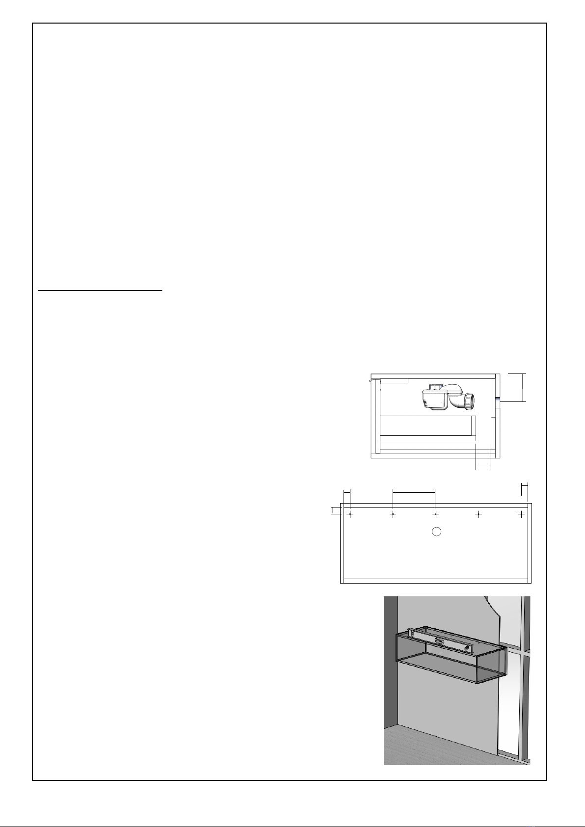
Fing the Bench Top & Basin
1. Place and posion the bench top onto the Fleet Frame’s
top surface.
2. Place the basin on the bench top and mark the waste
posion.
3. Mark the posion of the tapware if it is to be mounted
on the bench top. Please check to ensure there is
enough space behind the basin being installed. Larger
basins may require tapware to be mounted slightly to
the side. Note: there is a 45mm cavity behind the
drawer to accommodate exible hoses.
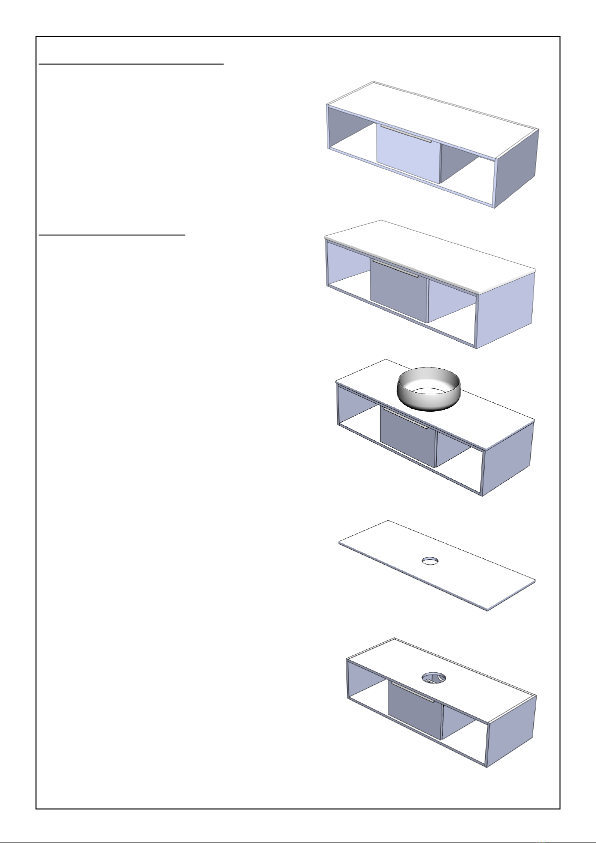
4. Through the centre of the basin waste and tap hole, drill a
pilot hole into the bench top and top of the Fleet Frame.
5. Remove the Benchtop and place on a rm at surface.
Using a hole saw cut the appropriate size holes for the
waste ng and the tap. A jigsaw with a high speed steel
blade can be used to cut the waste hole. If using a jigsaw,
mask the immediate area to protect the surface. Do not
cut square corners, corners must have a minimum 10mm
radius. If required, any cut edges can be smoothed using a
medium grit sandpaper.
6. Drill or cut the top surface of the Fleet Frame to accommo-
date the waste ng & tap. When cung the hole for the
waste and tap, it is recommended that the hole be larger
than that cut into the bench top e.g. if the bench top tap
hole is 35mm cut a 50mm hole in the Fleet Frame.
We suggest laying a towel inside the drawer to protect the
drawer runners being covered in debris. If any debris does
make its way onto the runners, use a vacuum cleaner to
remove.
Installing the Fleet Drawer connued

5
7. To the corners of the Fleet Frame apply a pea sized
amount of Silicone sealant.
8. Return the bench top to its nal resng posion and
gently push down into the sealant.
Fing the Benchtop & Basin
10. The basin can now be installed. Apply a pea sized amount
of Silicone sealant under the basin to hold it in place. Be
careful not to disrupt the posion of the bench top.
9. To prevent any accidental water ingress
apply a small bead of sealant around the
underside of the benchtop and to the wall.
It is recommended to mask the area to
achieve opmum results.
11. Allow 24 hours for the sealant to cure.
12. Installaon of tapware and plumbing can now proceed.

6
Removing the Drawer
1. Open the drawer fully.
2. On the underside of the Drawer locate the tabs on each side and press
the tabs while liing the Drawer and pulling towards the front at the
same me. This will release the Drawer from it’s runners.
Installing the Drawer
1. Place the Drawer over the runners.
2. Slide the Drawer inwards.
3. Push unl it clicks.
4. To ensure the Drawer is properly secured, hold the Drawer
front and pull the clip/runner on each side towards the Drawer
front. You will hear a click if the Drawer was not in posion;
this means the rear of the Drawer has located itself correctly
into a tab on the rear of the runner.
Rear locang tab
Pull clip forward
Press Tab

7
Adjusng Drawer Front Vercally ( +/- 2.0mm)
For further informaon on the drawer runner system, view and download full instrucons at:
hps://athena.co.nz/tekform-drawer-slimline-instrucons_jan18/
The Drawer front is secured to the Drawer box by the mecha-
nism and screws on the underside (refer images).
The screws are temporarily held in by tape to allow adjustment
of the Drawer front during installaon. Once nal adjustment is
achieved, ghten up these screws.
Loosen locking screw
Raise or lower Drawer front
Reghten locking screw
Table of contents
Popular Bathroom Fixture manuals by other brands

Graff
Graff ONDA E-7080-LM61N-T Instructions for assembly and use

Hans Grohe
Hans Grohe Raindance 27126000 Instructions for use

Franke
Franke STRATOS STRX671E Installation and operating instructions

Eurolux
Eurolux C85W quick start guide

Franke
Franke MIRANIT F5LM2025 Installation and operating instructions

Home Decorators Collection
Home Decorators Collection Leary HDC60HRV Assembly instructions

Signature Hardware
Signature Hardware HIBISCUS 948967 quick start guide

Salon & Co
Salon & Co artie SC2919 quick start guide

Kraus
Kraus Aplos KEF-15301 installation manual

Turin
Turin TU-SD-979-48-31C Installation and owner's manual

baliv
baliv KI-1130 manual

Allen + Roth
Allen + Roth HENDERSON 21-B472HCP-AR quick start guide