ATI Technologies Q-Blast Series User manual

O & M Manual
Auto-Clean Turbidity System
Home Office European Office
Analytical Technology, Inc. ATI (UK) Limited
6 Iron Bridge Drive Unit 1 & 2 Gatehead Business Park
Collegeville, PA 19426 Delph New Road, Delph
Phone: 800-959-0299 Saddleworth OL3 5DE
610-917-0991 Phone: +44 (0)1457-873-318
Fax: 610-917-0992 Fax: + 44 (0)1457-874-468

Table of Contents
PART 1 - INTRODUCTION................................4
1.1 General................................................4
1.2 Standard System.................................4
1.3 Features...............................................5
1.4 Q46/76 Auto-Clean System
Specifications.......................................7
1.5 Q46/76 Performance Specifications....8
1.6 Q-Blast Assembly................................8
PART 2 –ANALYZER MOUNTING..................9
2.1 General................................................9
2.2 Wall or Pipe Mount ............................9
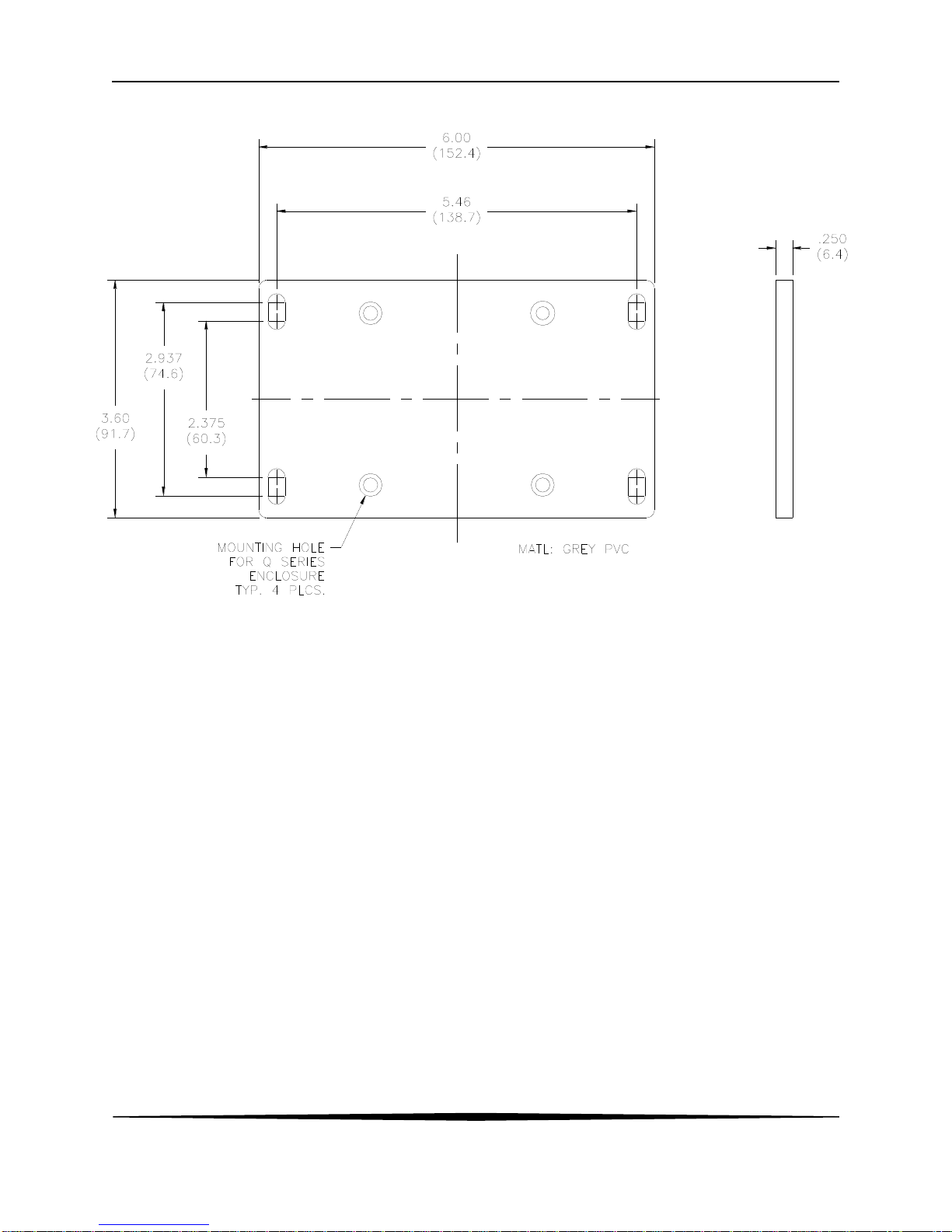
2.3 Wall Mount Dimensions..................10
2.4 Railing Mount...................................12
2.5 Sensor Assembly...............................13
2.6 Sensor Installation...........................14
PART 3 –ELECTRICAL INSTALLATION......16
3.1 General..............................................16
3.2 Connections.....................................16
3.3 Sensor Wiring....................................19
3.4 Q-Blast to Q46 Connection................20
3.5 Analog Output Connections...............23
3.6 Relay Connections.............................23
PART 4 –CONFIGURATION..........................24
4.1 User Interface ....................................24
4.11 Keys ...............................................25
4.12 Display ...........................................25
4.2 Software.............................................26
4.21 Software Navigation......................27
4.22 Measure Menu [MEASURE] ..........29
4.23 Calibration Menu [CAL]....................30
4.24 Configuration Menu [CONFIG]......30
4.25 Control Menu [CONTROL]............32
4.26 Diagnostics Menu [DIAG] ...............36
PART 5 –CALIBRATION ...............................40
5.1 Turbidity Calibration ..........................40
5.11 Cal Zero.........................................40
5.12 Cal Span........................................40
5.2 Temperature Calibration....................41
PART 6 - SENSOR AUTO-CLEAN SYSTEM.43
6.1 General.............................................43
6.2 Cleaner Sequence ...........................43
6.3 Cleaner Programming.....................44
PART 7 –PID CONTROLLER DETAILS........45
7.1 PID Description .................................45
7.2 PID Algorithm ....................................45
7.3 Classical PID Tuning.........................47
7.4 Manual PID Override Control............47
7.5 Common PID Pitfalls .........................47
PART 8 –SYSTEM MAINTENANCE..............49
8.1 General..............................................49
8.2 Analyzer Maintenance.......................49
8.3 Sensor Maintenance .........................49
PART 9 –TROUBLESHOOTING ...................50
9.1 General..............................................50
9.2 External .............................................50
9.3 Analyzer.............................................51
9.31 Display...............................................52
SPARE PARTS ...............................................53

3
O&M Manual
Rev-H (11/18)
Table of Figures
FIGURE 1-Q-BLAST SYSTEM...........................................................................................................................6
FIGURE 2-WALL/PIPE MOUNT BRACKET........................................................................................................10
FIGURE 4-Q-BLAST CLEANER DIMENSIONS...................................................................................................11
FIGURE 5-HANDRAIL MOUNTING ASSEMBLY..................................................................................................12
FIGURE 6-SENSOR ASSEMBLY......................................................................................................................13
FIGURE 7-SENSOR MOUNTING ASSEMBLY.....................................................................................................14
FIGURE 8-SENSOR MOUNTING DETAIL..........................................................................................................15
FIGURE 9-ELECTRICAL CONNECTIONS ..........................................................................................................17
FIGURE 10 -Q-BLAST CONNECTIONS .............................................................................................................18
FIGURE 11 -TURBIDITY SENSOR CONNECTION ...............................................................................................19
FIGURE 12 -ELECTRICAL CONNECTIONS ........................................................................................................21
FIGURE 13 -Q-BLAST CONNECTIONS W/OPTIONAL J-BOX...............................................................................22
FIGURE 14 -USER INTERFACE .......................................................................................................................24
FIGURE 15 -SOFTWARE MAP.........................................................................................................................28
FIGURE 17 -ALARM RELAY EXAMPLES ...........................................................................................................35
FIGURE 18 -ISA PID EQUATION ....................................................................................................................45
FIGURE 19 -DISPLAY MESSAGES...................................................................................................................52

4
O&M Manual
Rev-H (11/18)
Part 1 - Introduction
1.1 General
The Auto-Clean version of the Model Q46/76 is an on-line monitoring system designed for the
continuous measurement of turbidity in water and includes an air-blast sensor cleaning system. It
is intended for continuous monitoring of raw water, wastewater effluent, or other turbidity
applications where sample conditions dictate regular sensor cleaning.
The full scale operating range of the system 0-400 NTU. Actual display range is user
programmable for 0-2, 0-20, 0-200 or 0-400 NTU, and the system can also be programmed to
display in units of PSL for applications where polystyrene latex spheres are the standard of
measurement. The basic sensing element used in the turbidity system is an optical sensor
measuring light scattered at 90 degrees to the transmitted beam. The sensor provides an auto-
zeroing function to insure the highest sensitivity at very low turbidity levels.
Q46/76 Monitors are available in two electronic versions, an AC powered monitor with integral
alarm relays and dual 4-20 mA output capability, and a 12-24 VDC unit with dual output and
relays. Options are available to add either a third 4-20 mA output or 3 additional low power SPST
relays. In addition, a digital output option for Profibus, Modbus, or Ethernet is available.
1.2 Standard System
The Model Q46/76 Autoclean system includes three main components, a NEMA 4X electronics
unit, the “Q-Blast” NEMA 4X Air-Blast cleaning assembly, and a submersible Turbidity Probe with
cleaner nozzle. Probes are design for direct immersion in an aeration tank or flowing stream.
Probes come with a standard 30 ft. cable and connect directly to the Q46/76 Analyzer. A
separate tubing connection located on the Q-Blast assembly is provided for connection of a 30
foot length of plastic tubing (supplied with the unit). A typical system is shown in Figure 1.
Note that Error! Reference source not found. shows the Turbidity Analyzer and Q-Blast cleaner
ounted on ATI’s optional panel assembly with power distribution box. The panel and power
distribution box are not part of standard systems, and must be ordered separately using part
number (00-1637).
The Probe assembly is mounted to a 1" pipe using a special mounting adapter supplied as part of
the 00-0624 mounting assembly. The 1" pipe is attached to the tank handrail with a bracket
assembly that holds the sensor at a slight angle in the tank.
Once installed and placed into operation, the Q46/76 Auto-Clean system will provide months of
reliable measurement in almost any application. Probes should be checked for build-up after the
first 3 months to verify that the cleaner is keeping the sensor clean. However, sensor
maintenance intervals of 6 months or more are likely in most aeration tanks.
The sensor automatic cleaning frequency is user programmable, and units are shipped with a
default cleaning frequency of once every 24 hours. This frequency has proven sufficient for most
aeration applications, but can be increased if needed for a specific application. A cleaning
frequency of more than every 2 hours is not recommended. Contact your ATI representative for
more information if an 8-hour cleaning cycle does not keep the sensor clean

ATI Q46/76 Q-Blast Turbidity Monitor Part 1 - Introduction
5
O&M Manual
Rev-H (11/18)
1.3 Features
Standard Q46 electronic transmitters are designed to be a fully isolated instruments for
operation from either 90-260 VAC or 12-24 VDC power supplies.
Two 4-20 mA analog outputs are standard. One output may be configured for PID
control, while other output is programmable to track either Turbidity or Temperature.
Selectable PID controller on main analog output.
Digital communication option for Profibus-DP, Modbus-RTU, Modbus TCP/IP, or
Ethernet-IP.
Output Hold, Output Simulate, Output Alarm, and Output Delay Functions. All forced
changes in output condition include bumpless transfer to provide gradual return to on-line
signal levels and to avoid system control shocks on both analog outputs.
Units provide provides three SPDT relay outputs and two isolated analog outputs.
Software settings for relay control include setpoint, deadband, phase, delay, and failsafe.
Selectable Output Fail Alarm feature on Relay C allows system diagnostic failures to be
sent to external monitoring systems.
Large, high contrast, custom LCD display with LED back light provides excellent
readability in any light conditions. The secondary line of display utilizes 5x7 dot matrix
characters for clear message display two of four measured parameters may be on the
display simultaneously.
Diagnostic messages provide a clear description of any problem with no confusing error
codes to look up. Messages are also included for diagnosing calibration problems.
Security lock feature to prevent unauthorized tampering with transmitter settings. All
settings can be viewed while locked, but they cannot be changed.
Equipment bearing this marking may not be discarded by traditional methods in the
European community after August 12 2005 per EU Directive 2002/96/EC. End
users must return old equipment to the manufacturer for proper disposal.

ATI Q46/76 Q-Blast Turbidity Monitor Part 1 - Introduction
6
O&M Manual
Rev-H (11/18)
(System Diagram Shown on Optional Mounting Plate w/Power Distribution Box)
Figure 1 - Q-Blast System

ATI Q46/76 Q-Blast Turbidity Monitor Part 1 - Introduction
7
O&M Manual
Rev-H (11/18)
1.4 Q46/76 Auto-Clean System Specifications
Main Parameter Ranges Manual selection of one of the following display ranges,
0-2.000, 0-20.00, 0-200.0, or 0-2000 NTU
Note that the values above 400 on the 0-2000 display range
are not valid
Power 90 - 260 VAC, 50/60 Hz., 10 VA Maximum
12-24 VDC, 500 mA max.
Display 0.75” (19.1 mm) high 4-digit main display with sign
12-digit secondary display, 0.3" (7.6 mm) 5x7 dot matrix.
Integral LED back-light for visibility in the dark.
Enclosure NEMA 4X, polycarbonate, stainless steel hardware.
Analog Outputs Two 4-20 mA outputs. Output one programmable for NTU
Turbidity or PID. Output 2 programmable for NTU or
Temperature. Max load 450 Ohms for output 1 and 1000 ohms
for output 2. Outputs ground isolated and isolated from each
other. An additional 3rd analog option is available.
Output Isolation 600 V galvanic isolation
Optional Digital Output Profibus-DP, Modbus-RTU, or Ethernet-IP available.
Relays, Electromechanical Three SPDT, 6 amp @ 250 VAC, 5 amp @ 24 VDC contacts.
Software selection for setpoint, phase, delay, deadband, hi-lo
alarm, and failsafe. A-B indicators on main LCD, and C indicator
on lower display.
Weight Electronics Assembly: 2.4lbs. (1.1 kg)
Sensor Assembly: 2.5 lbs. (1.3 kg.)
Ambient Temperature Analyzer Service, -20 to 60 °C (-4 to 140 ºF)
Sensor Service, 0 to 55°C (23 to 131 °F)
Storage, -30 to 70 °C (-22 to 158 ºF)
Ambient Humidity 0 to 95%, non-condensing
Altitude Up to 2000 m (6562 ft)
Location Designed for hazardous and non-hazardous areas
EMI/RFI Influence Designed to EN 61326-1
Sensor Optical 90 degree scatter
Sensor Materials PVC and acrylic
Sensor Cable Submersible: 30 ft. (10 m)
Max. Sensor Cable Length 500 feet (153 m), with junction box

ATI Q46/76 Q-Blast Turbidity Monitor Part 1 - Introduction
8
O&M Manual
Rev-H (11/18)
1.5 Q46/76 Performance Specifications
Accuracy 0.5% of range or 0.03 NTU
Repeatability 0.3% of range or 0.02 NTU
Sensitivity 0.1% of selected range
Non-linearity 0.1% of selected range
Warm-up Time 30 seconds to rated performance (electronics only)
Supply Voltage Effects ± 0.1% span
Instrument Response Time 60 seconds to 90% of step input at lowest damping
1.6 Q-Blast Assembly
Power 90- 260 VAC, 50/60 Hz., 10 VA Maximum
12-24 VDC, 500 mA max.
Enclosure NEMA 4X, IP-66 polycarbonate, stainless steel hardware.
Compressor 12 VDC Diaphragm Type, 28 PSI (1.9 Bar) Maximum
Heater Internal thermostatically controlled.
Ambient Temperature Operating, -40 to 60 °C (-40 to 140 ºF)
Storage, -40 to 70 °C (-40 to 158 ºF)
Max. Air Tubing Length 60 feet (18.2 m)
Air Accumulator Powder coated stainless steel
Weight 3.7 lbs. (1.7 kg)

9
O&M Manual
Rev-H (11/18)
Part 2 – Analyzer Mounting
2.1 General
The Q46 Auto-Clean pH System consists of two assemblies housed in NEMA 4X (IP-66)
enclosures. The analyzer electronics and the Q-Blast cleaner assembly should both be mounted
near the sensor location, with a maximum of 30 feet between the monitor/cleaner and the sensor.
The standard system is supplied with a 30 ft. sensor cable and 30 feet of air line tubing. Best
performance is obtained by keeping sensor cable and air tubing length as short as practical
Installation of a complete Q46 Auto-Clean System requires mounting both the analyzer
electronics and the cleaner assembly, mounting the sensor assembly, and running a 3-conductor
interconnect wire between the analyzer and cleaner assemblies. Both the analyzer and the Q-
Blast assembly require power connection. If the system is purchased with optional mounting
plate and power distribution box, interconnect wiring will already be complete and only one power
connection is required at the junction box.
The analyzer enclosure and the cleaner enclosure may be mounted to any flat surface, like a wall
or plate. A bracket assembly is available (#00-0930) for mounting a flat PVC, aluminum, or
stainless steel plate to hold the two enclosures to typical aeration handrail systems. This bracket
locates the monitor at a convenient height for viewing the display and using the controls.
2.2 Wall or Pipe Mount
A PVC mounting bracket with attachment screws is supplied with each transmitter see Figure 2
for dimensions. The multi-purpose bracket is attached to the rear of the enclosure using the four
flat head screws. The instrument is then attached to the wall using the four outer mounting holes
in the bracket. These holes are slotted to accommodate two sizes of u-bolt that may be used to
pipe mount the unit. Slots will accommodate u-bolts designed for 1½ “or 2” pipe. The actual
center to center dimensions for the u-bolts are shown in the drawing. Note that these slots are for
u-bolts with ¼-20 threads. The 1½” pipe u-bolt (2” I.D. clearance) is available from ATI in type
304 stainless steel under part number (47-0004).

ATI Q46/76 Q-Blast Turbidity Monitor Part 2 –Analyzer Mounting
10
O&M Manual
Rev-H (11/18)
Figure 2 - Wall/Pipe Mount Bracket
2.3Wall Mount Dimensions
Figure 3 shows the dimensions of the analyzer dimensions. Note that the enclosure mounting
brackets are not installed at the factory. They are supplied separately and must be attached
using the screws provided. This is done to protect the brackets against shipping damage.
Figure 4 shows the dimensions of the Q-Blast assembly. This enclosure should be mounted
beside the analyzer enclosure as shown in Figure 4. If the optional mounting plate and power
junction box were purchased, the analyzer and cleaner will be supplied mounted to the plate.

ATI Q46/76 Q-Blast Turbidity Monitor Part 2 –Analyzer Mounting
11
O&M Manual
Rev-H (11/18)
Figure 3 - Wall Mount Analyzer Dimensions
Figure 3 - Q-Blast Cleaner Dimensions

ATI Q46/76 Q-Blast Turbidity Monitor Part 2 –Analyzer Mounting
12
O&M Manual
Rev-H (11/18)
2.4 Railing Mount
Figure 5 shows the optional mounting assembly (on system mounting plate) used to mount the
analyzer and cleaner assembly to a typical safety handrail that surrounds many aeration tanks.
This bracket assembly consists of vertical channels attached to the handrail with u-bolts. The
monitor screws to the channels with the 10-32 screws supplied as part of the kit. U-bolts for 2”
diameter handrail pipe are also supplied.
Figure 4 - Handrail Mounting Assembly

ATI Q46/76 Q-Blast Turbidity Monitor Part 2 –Analyzer Mounting
13
O&M Manual
Rev-H (11/18)
2.5 Sensor Assembly
The turbidity sensor is contained in a housing that acts as a light shield and also directs the
cleaning air across the face of the sensor. Figure 6 shows an exploded view of that assembly.
The sensor is already installed in the Autoclean holder when shipped from the factory. The
adapter is part of the optional mounting assembly shown in Figure 6. It is not normally necessary
to remove the sensor from the holder. If you do need to remove the sensor, the air delivery fitting
and washer must first be removed. The washer acts as a stop to keep the sensor from sliding out
of the holder at the back.
Figure 5 - Sensor Assembly

ATI Q46/76 Q-Blast Turbidity Monitor Part 2 –Analyzer Mounting
14
O&M Manual
Rev-H (11/18)
2.6Sensor Installation
Applications for Auto-Clean turbidity monitoring are done using a submersible sensor.
Submersible sensors are mounted to a 1" pipe using a standard 1" PVC thread by thread pipe
coupling. The mounting pipe can be secured to standard 1½” or 2” pipe rail using a mounting
bracket kit available from ATI (part number 00-0624) as shown in Figure 7 & Figure 8.
Figure 6 - Sensor Mounting Assembly

ATI Q46/76 Q-Blast Turbidity Monitor Part 2 –Analyzer Mounting
15
O&M Manual
Rev-H (11/18)
Figure 7 - Sensor Mounting Detail

16
O&M Manual
Rev-H (11/18)
Part 3 – Electrical Installation
3.1 General
Q46 Auto-Clean analyzers and Q-Blast cleaners are powered from 90-260 VAC, 50/60 Hz. or 12-
24 VDC. Systems can draw up to 0.5 amps when the internal air compressor activates as part of
the sensor cleaning system. Normal current draw is less than 0.2 amps when the cleaner is off.
Important Notes:
1. Use wiring practices that conform to all national, state and local electrical codes. For
proper safety as well as stable measuring performance, it is important that the earth
ground connection be made to a solid ground point from TB1.
2. Do NOT run sensor cables or instrument 4-20 mA output wiring in the same conduit that
contains AC power wiring. AC power wiring should be run in a dedicated conduit to
prevent electrical noise from coupling with the instrumentation signals.
3.2 Connections
Auto-Clean systems are generally AC powered, although a DC powered system is available.
Power connections are made to terminal TB7 in the monitor (Figure 8) and to TB1 in the Q-Blast
assembly (Figure 9).
AC or DC power should be brought into the enclosures through the bottom gland seal on the right
side of the enclosure. This entry is directly above the power terminal blocks. Terminal blocks are
pluggable, and can be removed for easy wire connection.

ATI Q46/76 Q-Blast Turbidity Monitor Part 3 –Electrical Installation
17
O&M Manual
Rev-H (11/18)
Figure 8 - Electrical Connections

ATI Q46/76 Q-Blast Turbidity Monitor Part 3 –Electrical Installation
18
O&M Manual
Rev-H (11/18)
Figure 9 - Q-blast Connections

ATI Q46/76 Q-Blast Turbidity Monitor Part 3 –Electrical Installation
19
O&M Manual
Rev-H (11/18)
3.3 Sensor Wiring
Sensor connections are made to a terminal block mounted on the front section of the monitor.
The sensor cable can be quickly connected to the Q46 terminal strip by matching the wire colors
on the cable to the color designations on the label in the monitor. Route signal cable away from
AC power lines, adjustable frequency drives, motors, or other noisy electrical signal lines. Do not
run sensor or signal cables in conduit that contains AC power lines or motor leads.
Figure 10 - Turbidity Sensor Connection

ATI Q46/76 Q-Blast Turbidity Monitor Part 3 –Electrical Installation
20
O&M Manual
Rev-H (11/18)
3.4 Q-Blast to Q46 Connection
Connections inside the Q-Blast enclosure include power and an interconnect cable running to the
Q46 monitor. To access the terminal compartment, loosen the 4 screws holding the cover in
place and set the cover aside. The screws are captive and should not come completely out of the
plastic cover.
As previously mentioned, power for the Q-Blast connects to TB1. An additional 3-conductor
cable must be connected between the Q46 analyzer and the Q-Blast cleaner as shown in Figure
12. The sequencing of the compressor and solenoid are controlled by the Q46, with control
signals carried by this cable.
Auto-Clean systems must be installed with the Q-Blast assembly no more than 60 ft. from the
sensor, and preferably much closer. However, the Q46 analyzer can be installed up to 500 ft.
from the cleaner assembly. This allows the display to be located at a convenient spot somewhat
remote from the sensor/cleaner location. When a remote cleaner installation is required,
interconnect the analyzer and the cleaner unit with 3-conductor, 22 AWG shielded cable as
shown in Figure 13. Do not run the interconnect cable in the same conduit with AC wiring. Note
also that a separate junction box is required for the sensor wiring if a remote monitor is to be
used. The 3-conductor control wire and the sensor signal wire may be run in the same conduit.
This manual suits for next models
4
Table of contents