ATIM Cloud Wireless DINDA User manual

ATIM Cloud Wireless
Analog sensor reading
DINDA
User Guide
Concerned models:
ACW/LW8-DINDA
ACW/SF8-DINDA

1
ATIM_ACW-DINDA_UG_FR_v1.5
TABLES OF CONTENTS
Document version history........................................................................................................................2
Disclaimer.................................................................................................................................................2
Trademarks and copyright .......................................................................................................................2
Declaration of compliance.......................................................................................................................3
Environmental recommendations ...........................................................................................................3
Explosive atmosphere .........................................................................................................................................3
Environment........................................................................................................................................................3
Radio....................................................................................................................................................................4
Technical specifications ...........................................................................................................................5
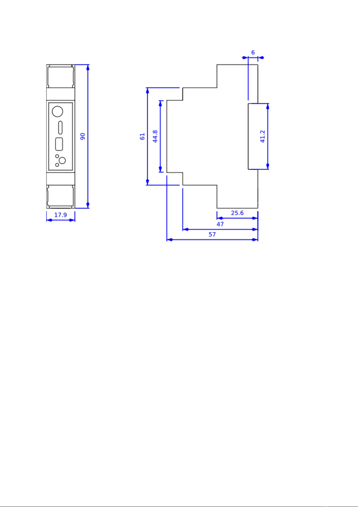
Footprint and installation ........................................................................................................................6
Set up .......................................................................................................................................................7
a. Positioning ..................................................................................................................................................7
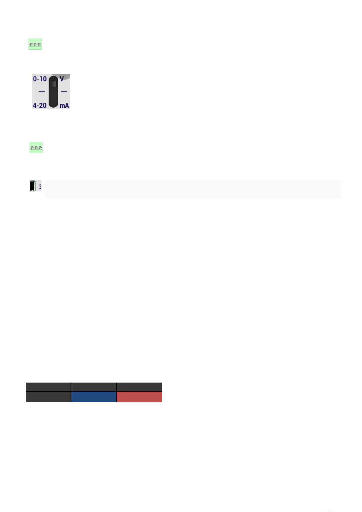
b. Modem connection.....................................................................................................................................7
c. Lights meaning............................................................................................................................................8
d. Pushbutton .................................................................................................................................................8
e. 10/30V digital inputs...................................................................................................................................9
Modem configuration............................................................................................................................10
a. Common configuration (calibration) ........................................................................................................11
b. Periodic mode configuration (SF8/LoRaWAN)..........................................................................................12
c. Threshold mode configuration (SF8/LoRaWAN).......................................................................................13
Frames formatting .................................................................................................................................16
Help........................................................................................................................................................18
The modem is not configured via USB or the configurator page does not update...........................................18
Radio data is not received .................................................................................................................................18
Modem LED does not flash................................................................................................................................18
Technical Support ..................................................................................................................................18

2
ATIM_ACW-DINDA_UG_FR_v1.5
Document version history
Disclaimer
The information contained in this document is subject to change without warning and does not represent a
commitment on the part of ATIM radiocommunications. ATIM radiocommunications provides this document
‘as-is’ with no warranty of any kind, express or implied, including but not limited to implied warranties of
merchantability or fitness for a particular purpose. ATIM radiocommunications may make changes and/or
improvements to this manual or to the product(s) or program(s) described in this manual, at any time.
Trademarks and copyright
ATIM radiocommunications®, ACW ATIM Cloud Wireless® and ARM Advanced Radio Modem® are registered
trademarks of ATIM SARL in France. The other trademarks mentioned in this document are the property of
their respective owners.
Version
Date
Description
Author
1.2
25/05/2016
Creation of the ACW DINDA User Guide
YL
1.3
22/11/2016
DIN casing
AM
1.4
09/03/2017
Corrections
FR
1.5
03/04/2020
Logic level digital inputs correction
SC

3
ATIM_ACW-DINDA_UG_FR_v1.5
Declaration of compliance
All ACW Atim Cloud Wireless® products comply with the regulatory requirements of the R&TTE Directive
(1999/5/EC), article 3:
1 SAFETY (Article 3.1a of the 1999/5/EC Directive)
NF EN60950-1 Ed. 2006/A1:2010/A11:2009/A12:2011 (health)
EN62479: 2010 (power <20mW) or EN62311:2008 (power > 20mW)
2 Electromagnetic compatibility (Article 3.1b of the 1999/5/EC Directive)
EN 301489-3 v1.4.1, EN 301489-1 V1.9.2
3 Efficient use of the radio frequency spectrum (Art.3.2 of the 1999/5/EC Directive)
ETSI EN300 220-2 v2.4.1 and EN300 220-1 v2.4.1
Environmental recommendations
Explosive atmosphere
Except for the ACW-ATEX line specifically intended for this purpose, do not use ACW radio modems in the
presence of flammable gases or fumes. Using the equipment in such an environment constitutes a safety
hazard.
Environment
Respect the temperature ranges for storage and operation of all products. Failing to respect these guidelines
could disrupt device operation or damage the equipment. ACW products in IP65 water- and dust-resistant
housings may be placed outdoors, but must not, under any circumstances, be submerged.
Follow the instructions and warnings provided below to ensure your own safety and that of the environment
and to protect your device from any potential damage.

4
ATIM_ACW-DINDA_UG_FR_v1.5
General hazard –Failure to follow the instructions presents a risk of equipment damage.
Electrical hazard –Failure to follow the instructions presents a risk of electrocution and physical injury.
Direct-current symbol
WARNING: do not install this equipment near any source of heat or any source of humidity.
WARNING: for your safety, it is essential that this equipment be switched off and disconnected from mains power
before carrying out any technical operation on it.
WARNING: the safe operation of this product is ensured only when it is operated in accordance with its intended
use. Maintenance may only be performed by qualified personnel.
Waste disposal by users in private households within the European Union. This symbol appears on a product or
its packaging to indicate that the product may not be discarded with another household waste. Rather, it is your
responsibility to dispose of this product by bringing it to a designated collection point for the recycling of electrical
and electronic devices. Collection and recycling waste separately at the time you dispose of it helps to conserve
natural resources and ensure a recycling process that respects human health and the environment. For more
information on the recycling centre closest to your home, contact your closest local government office, your local
waste management service or the business from which you purchased the product.
Radio
Modems in the ACW line are radio-communication modems that use the ISM (industrial,
scientific and medical) bands, which may be used freely (at no cost and with no authorisation required) for
industrial, scientific and medical applications.

5
ATIM_ACW-DINDA_UG_FR_v1.5
Technical specifications
Dimensions
90 x 57 x 67 mm
Antenna
External (SMA connector)
Temperature
-20°C to +55°C (operating)
-40°C to +70°C (storage)
Mounts to
DIN-Rail
Battery
1 x alimentation 10-30Vcc
Frequency
865 –870 MHz
Power
25 mW (14 dBm)
Rate
Sigfox: 100 bps
LoRaWan: 300 bit/s à 10 Kbit/s
Consumption
Sigfox
LoRaWan
Mode Tx
40 mA
35 mA
Mode Rx
35 mA
20 mA
Standby Mode
10 mA
10 mA

6
ATIM_ACW-DINDA_UG_FR_v1.5
Footprint and installation
Dimensions given in mm.
ACW modems in ‘breaker’ format are attached to a DIN-rail.

7
ATIM_ACW-DINDA_UG_FR_v1.5
Set up
a. Positioning
Install the modem at a minimum height of 2m and not glued to a wall, ideally offset by at least 20cm.
For best results, it is advisable to move the antenna up and clear of any metal obstacle within a radius of
1 meter if possible.
b. Modem connection
Terminals:
Antenna (SMA):
Before powering the product, a 50Ω / 868MHz antenna must be connected, either
directly to the SMA connector or via a 50Ω cable in case of antenna offset.
Alimentation device (Lower terminal):
The ACW-GW module must be powered with a DC power supply between 10V and
30V that can provide a minimum current of 100mA.
Alimentation analogical sensor (Lower terminal):
The analog sensor can be powered at the time of measurement directly with the output
OUT of the ACW_DA. To do this connect its power supply to the pin "OUT" and its GND to
that of the external power supply (or terminal GND). This output can deliver a max current of 1
ampere with the supply voltage (10 / 30V). Before each analog measurement, the sensor will be
powered for 0.5 seconds. If you want to permanently supply the sensor, do not use the "OUT"
connector and connect it directly to the terminals of the external power supply.
Name
Designation
Input / Output
GND
Ground
Input (alimentation)
10/30V
Alimentation between 10V and 30V
Ground
OUT
Alimentation sensor
Output TOR 10/30V (1A)
AN
Analogic input
Input 0/10V
|
4/20mA
IN2
Numerical input 2
Input TOR 10/30V
IN1
Numerical input 1
Input TOR 10/30V

8
ATIM_ACW-DINDA_UG_FR_v1.5
Analogical input (Upper terminal):
It is the analog input current or voltage that comes from the sensor.
To choose a voltage or current reading, in addition to indicating it in the configurator (see Modem configuration
section), it is necessary to switch the slide switch to the correct position. For use with a 0-10V
sensor, it is necessary to switch the switch to the high position (SMA side). For a
use with a sensor 4-20mA, it will switch the switch down (USB side).
Numerical inputs (Upper terminal):
You can connect up to two digital inputs. It is necessary to inject a voltage between 10 and 30V continous
or to leave the circuit open.
USB:
The USB connector is used to configure the ACW via a PC and a USB cable. for more detail. The
configuration must be done with the device powered by 10 / 30V.
c. Lights meaning
When the power is turned on or after removing the USB cable, the green LED (upper LED) lights up for
a brief moment signifies that the ACW is starting up properly. If a problem occurs during this phase, the
red LED (bottom LED) will illuminate for a brief moment to testify to this state.
In USB configuration mode, the green LED flashes until the configuration is completed and the USB cable
is removed.
Overall in normal operation, the illumination of the green LED attests to a radio communication. The
red LED illuminates to show any errors that may occur.
d. Pushbutton
The push button, located on the front of the box, allows to emit a test frame to validate the installation
on site. A test frame is constituted as follows.
Formatting frames' for more details):
Octet :
1
2
Data :
0x05
Metering
Note
The value ‘Counter’ is incremented with each press.

9
ATIM_ACW-DINDA_UG_FR_v1.5
e. 10/30V digital inputs
The digital inputs IN1 and IN2 have the following function:
Either trigger the analogue measurement on each rising or falling edge, then send the measured value
to the radio (Sigfox / LoRaWAN).
These inputs must be controlled by a voltage between 10V and 30V for an active state. The consumption
of these inputs is 30mA max at 30V and 10mA max at 10V.

10
ATIM_ACW-DINDA_UG_FR_v1.5
Modem configuration
Download and install the configuration software '' setupACW.exe '' at:
http://www.atim.com/produit/atim-cloud-wireless-acw/
Connect the module to your computer with a USB cable then launch the software, do not forget to supply
the ACW_RS in 10 / 30V.
When you connect the module, the software window changes to allow you to access the main features.
Automatically, the current configuration of the connected module is retrieved and displayed.
The different configuration modes are described below. Once the configuration is the one you want, you just
have to click on the Write key. After a few seconds of waiting, a message appears next to it to inform you if
the module update succeeded or failed.
Note
It is in this phase that the module is updated with the time of your PC.
Once the configuration is complete, do not leave the module connected to USB. This mode of
operation is very energy intensive. When you remove the USB link without disconnecting the
battery, the module automatically returns to normal operation. At power up, 5 test frames are
emitted every minute to validate the operation.

11
ATIM_ACW-DINDA_UG_FR_v1.5
a. Common configuration (calibration)
Note
In the lower part, you can read in real time (periodic sampling of 2s) the value measured by the
module.
✓Analog measurement
Here you can choose the type of measured value (current or voltage). You must also make
this choice on the slide switch (see Set Up).
✓Calibration
The 'Unit' field allows you to specify the unit of measure for data readability, up to 4
characters long. The 'minimum value' allows to set the minimum value for a sensor output
of 0V or 4mA. The 'maximum value' is used to set the maximum value for a sensor output
of 10V or 20mA.
✓Offset
Offset correction of the sensor + module assembly. Enter the value to add or subtract to the
measure to get the correct value. It is not recommended to correct the offset for an input of
0V or 0mA.

12
ATIM_ACW-DINDA_UG_FR_v1.5
b. Periodic mode configuration (SF8/LoRaWAN)
In this mode of operation, an analog measurement is performed and sent in radio every X time (X is a
configurable value).
✓Statement period
This menu allows you to configure the elapsed time between 2 sending of data. This
period is between 10min and 23h50min with a step of 10min.
✓Threshold
The high and low thresholds are not used in this mode, but they are still transmitted by
radio. Depending on your needs you can choose to configure them.

13
ATIM_ACW-DINDA_UG_FR_v1.5
c. Threshold mode configuration (SF8/LoRaWAN)
In this operating mode, an analog measurement is performed every X time (X is a configurable value). In
the case where the measured value is not between the two thresholds (configurable) the value will be
transmitted in radio.
✓Sampling period
This menu allows you to configure the elapsed time between 2 analog acquisitions. This
period is configurable every 15min, 30min, 1 hour or 2 hours.
✓Temperature sent
This makes it possible to force the sending every X time. Three times are configurable.
To activate and configure them you must check the appropriate boxes.
✓Threshold
During a measurement, it is compared with the high 'High' and 'Low' low thresholds. If
the measurement is outside these thresholds, the value will be sent only if the previous
measured value was between these two thresholds.

14
ATIM_ACW-DINDA_UG_FR_v1.5
Note
When a threshold is reached, it changes value, 5% greater for the low threshold and 5% smaller for the high threshold.
5% of the range of measurement. For example, if the min value is -2 and the max value is 14, Se will be 5% of 16

15
ATIM_ACW-DINDA_UG_FR_v1.5
Operating example
In this example the 'Sampling period' is set every hour and only one
'temperature sent'
is set to 13h. The
min value is 0 and the max value is 10. The threshold values could be 5V and 8V (black curve). This means
that if the measured value is outside thresholds (5V and 8V), the thresholds will be changed to 5% and will
become 5.5V and 7.5V (curve in gray).
The blue curve corresponds to the measured analog signal. The orange curves correspond to the analog
measurements. The green curves represent the sending of the measured analog value which has just
crossed a threshold. The yellow curve represents the sending of the measured analog value when the
'temperature feels'
is reached.

16
ATIM_ACW-DINDA_UG_FR_v1.5
Frames formatting
The first byte is a header, it defines the following data present in the frame. The useful elements therefore
vary according to the type of frame sent. The frames to the ACW-DA modem are :
TYPE DESCR. FORMAT DE LA TRAME
octet 0
(dec)
octet 0
(hex)
octet 1
(hex)
octet 2
(hex)
octet 3
(hex)
octet 4
(hex)
octet 5
(hex)
octet 6
(hex)
octet 7
(hex)
octet 8
(hex)
octet 9
(hex)
octet
10
(hex)
octet
11
(hex)
KEEP ALIVE
Trame de vie
1
01
Supply voltage
IDLE
(mV)
Supply voltage
TX
(mV)
64
VOLTAGE
READING
Trame de relevé
périodique d’une
valeur
0-10V
24
18
Logic
level
digital
inputs
Voltage value
Value min
Value max
Unité
CURRENT
READING
Trame de relevé
périodique d’une
valeur0-
20mA
25
19
Logic
level
digital
inputs
Current value
Value min
Value max
Unité
VOLTAGE
ALERT
TRESHOLD
LOW
Trame d’alerte BAS d’une
valeur
0-10V
30
1E
Logic
level
digital
inputs
Voltage value
Value min
Value max
Unité
CURRENT
ALERT
TRESHOLD
LOW
Trame d’alerte BAS d’une
valeur
4-20mA
34
22
Logic
level
digital
inputs
Courent value
Value min
Value max
Unité
VOLTAGE
END ALERT
TRESHOLD
LOW
Trame de fin
d’alerte
BAS d’une valeur
0-10V
31
1F
Logic
level
digital
inputs
Voltage value
Value min
Value max
Unité
CURRENT
END ALERT
TRESHOLD
LOW
Trame de fin
d’alerte
BAS d’une valeur
4-20mA
35
23
Logic
level
digital
inputs
Courent value
Value min
Value max
Unité
VOLTAGE
ALERT
TRESHOLD
HIGH
Trame d’alerte
HAUT d’une
valeur 0-10V
32
20
Logic
level
digital
inputs
Voltage value
Value min
Value max
Unité
CURRENT
ALERT
TRESHOLD
HIGH
Trame d’alerte
HAUT d’une
valeur 4-20mA
36
24
Logic
level
digital
inputs
Courent value
Value min
Value max
Unité
VOLTAGE
END ALERT
TRESHOLD
HIGH
Trame defin
d’alerte
HAUT d’une valeur0-
10V
33
21
Logic
level
digital
inputs
Voltage value
Value min
Value max
Unité
CURRENT
END ALERT
TRESHOLD
HIGH
Trame de fin
d’alerte
HAUT d’une
valeur 4-20mA
37
25
Logic
level
digital
inputs
Courent value
Value min
Value max
Unité
TEST
Trame de test
5
05
CNTR

17
ATIM_ACW-DINDA_UG_FR_v1.5
The data is decoded as follows:
Example of a received frame
(hex) 1920C4510000FFFF00000000
‘Frame type’ = (hex)19 = 25=> ‘Index periodic frame’
‘Logic level CUT’ = (hex)20 => ‘Input 1 at “1” and Input 2 at “0” ‘.
‘Voltage value’ = (hex)C451 => ‘Measured tension value’ = 0xC451 = (dec)50257 => 50257 * (( 10-0 ) /
64240) => 7,8 V
Logic level
digital inputs
Bit
7
6
5
4
3
2
1
0
Octet 1
NC
NC
Input 1
Input 2
NC
NC
NC
NC
Voltage Value
Octets 2 & 3
V(V) = VOLTAGE * (( 10-0 ) / 64240)
Current Value
Octets 2 & 3
C(mA) = CURRENT * (20-4)/47584

18
ATIM_ACW-DINDA_UG_EN_v1.5
Help
The modem is not configured via USB or the configurator page does not update
•Check if the power supply is properly connected to the modem
•Check if the light is flashing
•Check that "Windows Update" is enabled, that the PC is connected to the Internet and that the driver
installation is complete. Also check that your version of the configurator is up to date (Menu File ->
Update).
•Replace the USB cable
•In case of Failed to write the configuration, unplug and reconnect the USB cable
Radio data is not received
•Check if the power supply is properly connected to the modem
•Check if the modem has been registered on the network
•Check if radio network coverage is available
Modem LED does not flash
•Check if the power supply is properly connected to the modem
•Configure the modem using the USB configurator
Technical Support
For any information or technical problems, you can contact our technical support:
https://www.atim.com/en/support-2/technical-support/
This manual suits for next models
2
Table of contents
Other ATIM Accessories manuals
Popular Accessories manuals by other brands

Kampa
Kampa Rally AirPro 260 instruction manual

Pfeiffer Vacuum
Pfeiffer Vacuum RPT 010 operating instructions

HAUL MASTER
HAUL MASTER 30329 operating instructions

Baumer
Baumer OADM 20I6480/S14F quick start guide

Victron energy
Victron energy Smart Battery Sense manual

Airflow
Airflow RF MEV WH4H Operation and service guide