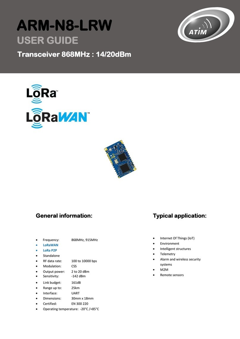
ATIM ARM-N8-LD User manual

Advanced radio modems
Nano transceiver modules
N8-LD/LP
User Guide
Concerned models:
ARM-N8-LD (Long distance)
ARM-N8-LP (Low power)
ARM-N8-SF (Sigfox)

2
ATIM_ARM-N8-LD-LP_UG_EN_V2.0
TABLE OF CONTENTS
Document version history............................................................................................................................... 4
Disclaimer........................................................................................................................................................ 4
Trademarks and copyright .............................................................................................................................. 4
Declaration of compliance .............................................................................................................................. 5
Environmental recommendations .................................................................................................................. 5
Environment ........................................................................................................................................5
Radio.................................................................................................................................................... 6
Radio regulations ............................................................................................................................................ 7
i. Context....................................................................................................................................................... 7
ii. Information about the regulation and the conformity ..............................................................................7
Generalities..................................................................................................................................................... 9
i. Presentation...............................................................................................................................................9
ii. ARM range and ACW range........................................................................................................................ 9
iii. Soldering & Environment ........................................................................................................................... 9
Technical features......................................................................................................................................... 10
i. Electrical and mechanical characteristics................................................................................................. 10
ii. Dimensions............................................................................................................................................... 10
iii. Pins........................................................................................................................................................... 11
iv. Consumption features.............................................................................................................................. 11
v. Link interfaces .......................................................................................................................................... 12
vi. Firmware update...................................................................................................................................... 12
vii. RF features ............................................................................................................................................... 13
viii. Delay......................................................................................................................................................... 13
ix. Memory.................................................................................................................................................... 14
Hardware integration.................................................................................................................................... 15
i. Power supply............................................................................................................................................ 15
ii. Impedance of the antenna adaption........................................................................................................15
iii. Print and ground plan............................................................................................................................... 15
AT command configuration........................................................................................................................... 16
Test modes.................................................................................................................................................... 17
i. Ping-pong mode (ATT00 and ATT01)........................................................................................................17
ii. Continuous reception mode (ATT02) ....................................................................................................... 17
iii. Pure carrier (ATT04) ................................................................................................................................. 17
iv. RSSI reading (ATT0A) ................................................................................................................................ 17
v. Version ..................................................................................................................................................... 18
Interfaces ...................................................................................................................................................... 19
i. Selection................................................................................................................................................... 19
ii. UART mode............................................................................................................................................... 19

3
ATIM_ARM-N8-LD-LP_UG_EN_V2.0
iii. UART Configuration (in yellow: by default).............................................................................................. 20
iv. Serial buffers ............................................................................................................................................ 21
v. Mode SPI .................................................................................................................................................. 22
Operating mode............................................................................................................................................ 26
i. Transparent (serial/RF bridge: ARM-N8-LP/LD) ....................................................................................... 26
ii. Sigfox Uplink (ARM-N8-SF)....................................................................................................................... 32
Radio part...................................................................................................................................................... 34
i. Principal parameters (by default)............................................................................................................. 34
ii. Header...................................................................................................................................................... 34
iii. Radio channels ......................................................................................................................................... 36
iv. Whitening................................................................................................................................................. 36
v. Listen before talk (LBT)............................................................................................................................. 37
vi. Adaptive Frequency Agility (AFA)............................................................................................................. 38
vii. Repeater................................................................................................................................................... 38
Sleep mode ................................................................................................................................................... 39
i. Sleep/wake-up sources ............................................................................................................................ 39
ii. Entrance and exit of the sleep mode condition ....................................................................................... 39
Wake On Radio (WOR).................................................................................................................................. 41
i. Principal.................................................................................................................................................... 41
ii. WOR reception method ........................................................................................................................... 42
iii. Post-WOR treatment................................................................................................................................ 42
iv. Wake up events (example)....................................................................................................................... 43
Signalizations................................................................................................................................................. 45
Measured current at 3,3V............................................................................................................................. 46
Consumed current Optimization................................................................................................................... 47
Firmware update by bootloader................................................................................................................... 48
i. Versions.................................................................................................................................................... 48
ii. Using the Upgrader.exe............................................................................................................................ 48
Frequency table ............................................................................................................................................ 49
AT registers table .......................................................................................................................................... 61

4
ATIM_ARM-N8-LD-LP_UG_EN_V2.0
Document version history
Disclaimer
The information contained in this document is subject to change without warning and does not represent a
commitment on the part of ATIM radiocommunications. ATIM radiocommunications provides this document ‘as-is’
with no warranty of any kind, express or implied, including but not limited to implied warranties of merchantability
or fitness for a particular purpose. ATIM radiocommunications may make changes and/or improvements to this
manual or to the product(s) or program(s) described in this manual, at any time.
Trademarks and copyright
ATIM radiocommunications®, ACW ATIM Cloud Wireless® and ARM Advanced Radio Modem® are registered
trademarks of ATIM SARL in France. The other trademarks mentioned in this document are the property of their
respective owners.
Version
Date
Description
Author
1.0
17/05/2014
Creation
TD
1.4
13/05/2014
WOR mode, new frequencies table,
Declaration of conformity, SPI mode, Repeater mode, Signalizations
TD
1.5
25/11/2015
Sigfox Uplink
TD
1.6
02/12/2015
Document title, post-WOR
TD
1.7
07/12/2015
UART parity correction
TD
1.8
25/11/2015
RSSI-PWM unavailable on Sigfox modems
TD
1.9
30/03/2016
Various corrections (Radio and consumption)
TD
2.0
02/06/2020
Document format and translation
MD

5
ATIM_ARM-N8-LD-LP_UG_EN_V2.0
Declaration of compliance
All ARM Advanced Radio Modems® products comply with the regulatory requirements of the R&TTE Directive
(1999/5/EC), article 3:
1 SAFETY (Article 3.1a of the 1999/5/EC Directive)
EN62311:2008 Human Exposure Restrictions for Electromagnetic Fields
EN61000-6-2: 2005 Electromagnetic compatibility (EMC) - Immunity for industrial environments
2 Electromagnetic compatibility (Article 3.1b of the 1999/5/EC Directive)
EN 301489-3 v1.4.1, EN 301489-1 V1.9.2
3 Efficient use of the radio frequency spectrum (Art.3.2 of the 1999/5/EC Directive)
ETSI EN300 220-2 v2.4.1 and EN300 220-1 v2.4.1
Receiver class: 2
It is under the responsibility of the user to unsure that the configuration and the usage of the
ARM-N8-LDLP fills in all the conditions 70-03 of the REC (describing the annex 1, the radio bands, g, G1, G2, G3 or
G4).
Environmental recommendations
Environment
Respect the temperature ranges for storage and operation of all products. Failing to respect these guidelines could
disrupt device operation or damage the equipment.
Follow the instructions and warnings provided below to ensure your own safety and that of the environment and to
protect your device from any potential damage.

6
ATIM_ARM-N8-LD-LP_UG_EN_V2.0
General hazard –Failure to follow the instructions presents a risk of equipment damage.
Electrical hazard –Failure to follow the instructions presents a risk of electrocution and physical injury.
Direct-current symbol
WARNING: do not install this equipment near any source of heat or any source of humidity.
WARNING: for your safety, it is essential that this equipment be switched off and disconnected from mains power
before carrying out any technical operation on it.
WARNING: the safe operation of this product is ensured only when it is operated in accordance with its intended
use. Maintenance may only be performed by qualified personnel.
Waste disposal by users in private households within the European Union. This symbol appears on a product or
its packaging to indicate that the product may not be discarded with another household waste. Rather, it is
your responsibility to dispose of this product by bringing it to a designated collection point for the recycling of
electrical and electronic devices. Collection and recycling waste separately at the time you dispose of it helps
to conserve natural resources and ensure a recycling process that respects human health and the environment.
For more information on the recycling centre closest to your home, contact your closest local government office,
your local waste management service or the business from which you purchased the product.
Radio
Modems in the ARM line are radio-communication modems that use the ISM (industrial, scientific,
and medical) bands, which may be used freely (at no cost and with no authorisation required) for industrial, scientific
and medical applications.

7
ATIM_ARM-N8-LD-LP_UG_EN_V2.0
Radio regulations
i. Context
The modems from the ARM and ACW range are part of the radio communication that use the ISM (Industry Scientific
Medical) band that can be use freely (free and without authorization) for industrial, scientific, and medical
applications.
A regulation has been put in place at a national and worldwide standard to control interferences and saturation of
the radio bands. For the national, la regulation is insured by the ANFR (National frequencies Agency) and the ART
(Regulation Authority of Telecommunications). The ANFR was created in 1996, they elaborated and edited the
national distribution of the radio bands based on the radio regulation made as part of the UIT.
Concerning the civil applications, the conditions are fixed by the ART who decides the frequencies with a planning.
This planning is done by cutting in regions which is also cut in different bands. Then every radio communication
service is defined and a list of operators. A distinction by category is done, we can find the ministries (Defense,
Research, Interior), the ART and the CSA.
ii. Information about the regulation and the conformity
Utilization of radio frequencies is limited by national regulations. Radio modules are conceived to follow the R&TTE
(Radio & Telecommunications Terminal Equipment) directive 1999/5 / CE from European Union and can be freely
used in European Union. Nevertheless, restrictions regarding RF power or duty cycle can be applied.
The ARM-N8-LD/LP is a radio module conceived to be integrated in another product, often final products. According
to the R&TTE directive, the final product producer is responsible of the conformity declaration for this product. The
ARM-N8xx module conformity declaration is available on demand at ATIM, however, it does not cover the product
where it is integrated in.
Regulation requirements can change, ATIM does not take responsibility of the exactitude and precision.
Legislation and national regulations, just as their interpretation can vary accordingly to the country. In case of
uncertainty, it is recommended to contact ATIM or to consult local authorities in the concerned country.
Figure 1 : ISM bandwidths use around the world

8
ATIM_ARM-N8-LD-LP_UG_EN_V2.0
Frequency Band
Power/Magnetic
Field
Spectrum access and
mitigation
requirements
Modulation/
maximum occupied
bandwidth
ECC/ERC
Decision
Notes
g1
863-870
MHz (notes
3 and 4)
25 mW e.r.p.
≤ 0.1% duty cycle or
LBT (notes 1 and 5)
≤ 100 kHz for 47 or
more channels (note
2)
FHSS
25 mW e.r.p.
Power density:
-4.5 dBm/100kHz
(note 7)
≤ 0.1% duty cycle or
LBT+AFA
(notes 1, 5 and 6)
No spacing
DSSS and other
wideband techniques
other than FHSS
25 mW e.r.p.
≤ 0.1% duty cycle or
LBT+AFA
(notes 1 and 5)
≤ 100 kHz,
for 1 or more
channels
modulation
bandwidth
≤ 300 kHz
(note 2)
Narrow /wide band
modulation
g1.1
868-868.6
MHz
(note 4)
25 mW e.r.p.
≤ 1% duty cycle or
LBT+AFA (note 1)
No spacing,
for 1 or more
channels
(note 2)
Narrow / wide band
modulation.
No channel spacing,
however, the whole
stated frequency band
may be used
g1.2
868.7-869.2
MHz
(note 4)
25 mW e.r.p.
≤ 0.1% duty cycle or
LBT+AFA
(note 1)
No spacing,
for 1 or more
channels
(note 2)
Narrow / wide band
modulation.
No channel spacing,
however, the whole
stated frequency band
may be used
g1.3
869.4-
869.65 MHz
500 mW e.r.p.
≤ 10% duty cycle or
LBT+AFA
(note 1)
No spacing,
for 1 or more
channels
Narrow / wide band
modulation
The whole stated
frequency band may be
used as 1 channel for
high speed data
transmission
g1.4
869.7-870
MHz
(note 11)
5 mW e.r.p.
25 mW e.r.p.
No requirement
≤1% duty cycle or
LBT+AFA
(note 1)
No spacing
for 1 or more
channels
Narrow / wide band
modulation.
No channel spacing,
however, the whole
stated frequency band
may be used
Tableau 1: frequencies’bandwidths applicable to the 868 MHz bandwidth for
"Nonspecific to short range devices" specified in the ERC 70-03, [2].

9
ATIM_ARM-N8-LD-LP_UG_EN_V2.0
Generalities
i. Presentation
In order to answer more accurately to various user challenges, ATIM started a new device family called Nano-
Modules composed of different modules using state of the art technologies like Ultra Narrow Band (UNB), Narrow
Band (NB) and Chirp Spread Spectrum (CSS). This family has been developed for users requiring high communication
range.
In fact, all the ARM-N8Lx devices have a range further than 22 km considering sight, the ARM-N8LORA exceeds 25
km and the ARM-N1LD (169Mhz) goes over 40 km. Some modules can also benefit an extended range with the
repeater functionality.
ARM-N8LP/LD have double functionality; they can be used in local mode (P2P) (ISM network) and/or in SIGFOX
networks (SIGFOX™ network). ARM-N8LORA can also be used in two mode, point to point LoRa communication or
FSK local mode (P2P).
Every module is optimized to get the lowest power consumption possible, allowing users to develop battery powered
devices. With the right batteries and configuration, a module can be used up to 10 years without changing batteries.
Every module is pin to pin compatible, allowing users to get different communication possibilities without having to
redesign their hardware.
ii. ARM range and ACW range
Since 2014, the ARM product range has been replaced by the ACW range. The ARM-Nano radio modules managed
the transition between the two ranges insuring the radio compatibility.
The AT commands of the old modules ARM-U8 or ARM-C8 are not compatible with the ARM-Nano (The AT
commands addresses stay compatible).
The Nano product range is available in N8: 868MHz:
▪N8-LP: Low Power module (P=14dBm)
▪N8-LD: Long distance module (P= 27dBm)
iii. Soldering & Environment
Before implementing of soldering the ARM-N8 module, it needs to be totally disconnected from the power
supply. It is forbidden to change components while the power supply is still connected.
This would damage the equipment. Keep away from any humidity, do not pour any liquid on the module. The
Arm radio module is supposed to be used inside and at an altitude less than 2000 meters.

10
ATIM_ARM-N8-LD-LP_UG_EN_V2.0
Technical features
i. Electrical and mechanical characteristics
ii. Dimensions
For the ARM-Nx-LD or Nx-LP, the dimensions are similar.
Dimensions
30 x 18 x 2,5 mm (25 pins)
Radio Regulation
EN 300 220 V2.4.1
Operating Temp
-20°C to +70°C
Modulation
2GFSK/4GFSK
Sensitivity
-122dBm @1,2kbps BER10-3
Range
>20 km (FEL)
Frequency
863 –870 MHz
Output power max
500 mW (27 dBm)
Data rate
100 bit/s to 115,2 Kbit/s
Radio consumption (Tx)
500 mA (27dBm)
Sleep consumption
1µA (ARM N8LP), 2.5 µA (ARM N8LD)
Radio consumption (Rx)
26 mA
Interface (max)
UART (0,2MHz)/SPI (1,3MHz)
Setup
AT cmds / SPI cmds / Modbus registers
Features
LBT, AFA, FastUARTwakeUp, WakeOnRadio, Repeater
SMD Mounting
18mm
30mm

11
ATIM_ARM-N8-LD-LP_UG_EN_V2.0
iii. Pins
iv. Consumption features
PIN
NAME
I/O
FUNCTION
1
AGND
-
GROUND
2
ANTENNA
-
RF SIGNAL
3
AGND
-
GROUND
4
AGND
-
GROUND
5
OSC1
I
QUARTZ INPUT
6
OSC0
I
QUARTZ INPUT
7
MOSI
I
PORT SPI SLAVE DATA IN
8
!SS
I
PORT SPI SLAVE CHIP SELECT
9
MISO
O
PORT SPI SLAVE DATA OUT
10
SCLK
I
PORT SPI SLAVE CLOCK
11
SMSG
O
OUTPUT MESSAGE RADIO PENDING
12
DGND
-
GROUND
13
DGND
-
GROUND
14
VDD
-
POWER SUPPLY
15
INT0
I
INPUT INTERRUPTIBLE / WAKE UP
16
U1CTS
I
CLEAR TO SEND UART
17
U1RTS
O
REQ. TO SEND UART
18
U1RX
I
RX UART
19
U1TX
O
TX UART
20
RSSI
O
ANALOG OUTPUT or DIGITAL
21
AN0
I
ANALOG INPUT
22
RESET
I
INPUT RESET MCU
23
AGND
-
GROUND
24
AGND
-
GROUND
25
AGND
-
GROUND
Min.
Typ.
Max.
Power supply (Vdd)
3V
3,3V
3,6V
Consumption at 3,3V
Tx / 25mW
-
50mA
60mA
Tx / 500 mW (LD version)
-
700mA
900mA
Rx
-
31mA
45mA
Sleep
0,7µA
1µA
2,5µA
Input voltage
GND
-
0,2 x VDD
Output voltage
0,8 x VDD
-
VDD

12
ATIM_ARM-N8-LD-LP_UG_EN_V2.0
v. Link interfaces
▪UART 2 wires + flow control by RTS/CTS (1200 –230400 bps)
▪SPI Slave (≤2MHz)
▪1 wake up input
▪1 digital output « signalization »
▪1 analog output 12 bits (option)
▪functioning mode:
✓Transparent mode « UART/RF bridge » or « SPI/RF bridge »
✓Slave Modbus mode
✓Master Modbus mode (specifications are required)
✓Repeater mode
✓Configuration mode « AT » local and distant
✓Test modes: Ping-pong, pure carrier, continuous request, RSSI reading
vi. Firmware update
The software embedded on ARM-N8-LD/LP modules can be updated via the software ds30Loader (compatible with
Windows/Mac/Linux) via UART. The file is available on demand.
Figure 2 : Sofware for the firware’s update

13
ATIM_ARM-N8-LD-LP_UG_EN_V2.0
vii. RF features
N8: 863 –870MHz: 553 available channels (in short bandwidth)
The ARM-N8 modules are usually, set on the channel 869.525MHz (channel 522 / 0x020A) speed of 1200bps.
The range is done at 3m from the ground ½ wave antennas.
viii. Delay
Delay
Launch
slow (with bootloader)
3s
fast (without bootloader)
20ms
Buffer of the UART characters
2µs
Emission characters UART >> RF
Packaging mode
3 x bytes after the last UART character received
Endless mode
immediate after the last UART character
received
Reception characters RF >> UART
Packaging mode
immediate after the last RF byte received
Endless mode
Immediate after receiving the preamble
Radio turnaround time
(Tx-Rx or Rx-Tx)
30µs
Configuration Input
(AT commands)
Immediate after receiving '+++'
Configuration output
(AT commands)
120ms after receiving 'ATQ'
Sleep mode input
'0' on pin INT0
10ms after end of radio activity
Sleep mode output
'1' on pin INT0
10ms
Channels at
14dBm / 25mW
Channels at
27dBm/500mW
Mode
Data rate (bps)
Number of modules
symbols (GFSK)
Narrow band
Rejection adjacent
channel (N-1/N+1)
Rejection alternance
channel (N-2/N+2)
Blocking at +/-1 MHZ,
+/-2 MHz, +/- 10 MHz
Sensibility in dBm (BER
@10-3)
Number of channels
Range measured at 3m
from the ground FEL
Number of channels
Range measured at 3m
from the ground FEL
1200
2
YES
-48dBc
-48dBc
-48dBc
-123
553
19
20km
2400
2
YES
-46dBc
-46dBc
-46dBc
-122
553
19
4800
4
YES
-43dBc
-43dBc
-43dBc
-119
553
19
9600
4
NO
-45dBc
-46dBc
-46dBc
-118
273
9
18km
19200
4
NO
-41dBc
-41dBc
-42dBc
-116
180
5
38400
4
NO
-40dBc
-32dBc
-42dBc
-113
137
7
57600
4
NO
-40dBc
-30dBc
-46dBc
-112
88
3
115200
4
NO
-37dBc
-42dBc
-50dBc
-106
33
1
COMPATIBLE
9600
2
NO
3
3
19200
2
NO
3
3
38400
2
NO
3
1

14
ATIM_ARM-N8-LD-LP_UG_EN_V2.0
ix. Memory
Function
Memory type
Placing
Capacity (bytes)
Bootloader + Firmware + Serial number
Flash
MCU
32k
AT commands backup
EEPROM
MCU
512
Buffer serial Rx
RAM
MCU
512
Buffer serial Tx
RAM
MCU
256
Buffer Radio Rx
RAM
MCU
128
Buffer Radio Tx
RAM
MCU
128
Special Backup (on demand)
Flash
External
2M

15
ATIM_ARM-N8-LD-LP_UG_EN_V2.0
Hardware integration
i. Power supply
The module power supply is between 2,7V and 3,6V. To guaranty a correct filter for the supply the filter LC Figure 3
must be put into place the closest to the pin VDD.
Figure 3 : power supply filter
ii. Impedance of the antenna adaption
The passive components to integrate between the antenna and the RF pin of the ARM-N8 module depends on the
length of the electronic track, of the dielectric and the antenna that is chosen. For a rapid implementation, a serial
condenser of 68pF can be used. The other components are optional and do not need to be wired.
Figure 4 : impedance adaptation
iii. Print and ground plan
It is recommended to cover the whole surface under the ARM-N8 module with a ground plan. This surface must be
varnished to avoid any short. It is advised not to put vias on this surface.

16
ATIM_ARM-N8-LD-LP_UG_EN_V2.0
Figure 5 : Ground plan footprint
AT command configuration
The UART link is at 19200bps as standard, 8 bytes data, no parity, 1 stop byte, Without flow control.
To go into AT command mode who must:
➢Send three consecutives ‘+’characters: Manual mode with 3 individuals ‘+’ via terminal. In transparent
mode, this method will send at the same time two ‘+’ by radio.
➢Send three ‘+’characters: Packaged 3 ‘+’ characters. In transparent mode, this method does not send
three ‘+’ by radio.
The memorization of the parameters is instantaneous and applied after a reset, ON/OFF, ATR, ATQ. For a running
configuration (without EEPROM writing), it is recommended to use the ATH commands then ATI for a reboot with
the new parameters.
Command
Function
+++
AT command enter
ATQ + ENTER
AT command exit
ATR + ENTER
MCU Reset
ATI + ENTER
MCU Reboot
ATS'XXX' + ENTER
Reading EEPROM of the register SXXX. XXX decimal value
ATS'XXX'='YY' + ENTER
Writing EEPROM of the register SXXX. XXX decimal value, YY hexadecimal value
ATH'XXX' + ENTER
Reading RAM of the register HXXX. XXX decimal value
ATH'XXX'='YY' + ENTER
Writing RAM of the register HXXX. XXX decimal value, YY hexadecimal value
ATF + ENTER
Reset in factory mode
ATV + ENTER
Modem version
ATL + ENTER
ATS registers list
RAM
EEPROM
FLASH
COPY
COPY
ATF
Version
updated ?
YES
ATS
ATH
UART
CTS=‘0’ ?
ATI
ATQ
RESET
ATR
INIT
NO
Com. with
bootloade
r app
BOOTLOADER
UPDATING
NO
YES
RUN
YES
FIRMWARE
Timeout
3sec
NO
NO
YES

17
ATIM_ARM-N8-LD-LP_UG_EN_V2.0
Test modes
Cmd
Function
+++
AT command enter
ATT'ZZ' +
ENTER
Testing mode 'ZZ' :
Keyboard commands:
ZZ = 00 : Ping-Pong Master
'a' : exit current test mode
ZZ = 01 : Ping-Pong Slave
'z' : increase radio emission power
ZZ = 02 : Continuous reception
's' : reduce radio emission power
ZZ = 03 : BER result
'q' : reduce the frequency from one channel
ZZ = 04 : Emission pure carrier
'd' : increase the frequency from one channel
ZZ = 05 : NC
'x' : lowers the period (ping-pong mode , reading rssi)
ZZ = 06 : NC
'c' : increase the period (ping-pong mode , reading rssi)
ZZ = 07 : NC
'e' : deducts the destination number
ZZ = 08 : NC
'r' : increases the destination number
ZZ = 09 : NC
't' : activates/deactivates the repeater
ZZ = 0A : RSSI value on current
channel
ZZ = 0B : sleep mode enter (exit by
sending characters)
ZZ = 0C : NC
ZZ = 0D : Reset BER result
i. Ping-pong mode (ATT00 and ATT01)
Every active module act like a slave ping-pong and is ready to answer to master ping-pong requests without the user
needing to manually go into ping-pong slave mode. The power can be reduced or increased with ‘z’ or ‘s’, the
frequency with ‘q’ or ‘d’. The radio protocol addresses can be increased or deducted with ‘e’ or ‘r’.
ii. Continuous reception mode (ATT02)
This mode allows to the receive the frames sent by a distant modem and to put an RSSI statue message and the end
of the frame. Display BER / PER (ATT03) results
A link budget is described with many characters by different criteria with an error rate of the exchanged packets and
the number of totals of wrong bytes. These meters can be erased with the command ATT0D.
iii. Pure carrier (ATT04)
A pure carrier with an undefined time can be configured to appreciate the output power, the current consumed in
Tx, or in the case of antenna alignment, the orientation of this one compared to a distant modem in RSSI reading
mode. The power can be reduced or increased with ‘z’ or ‘s’, the frequency with ‘q’ or ‘d’. This command must be
temporary and not disturb another system.
iv. RSSI reading (ATT0A)
This mode sends the actual RSSI averaged on a time interval that can be reduced or increased with ‘x’ or ‘c’. The
frequency can be reduced or increased with ‘q’ or ‘d’.

18
ATIM_ARM-N8-LD-LP_UG_EN_V2.0
Figure 6 : Terminal in test mode
v. Version
From the command mode, it is possible to get these information’s via the command « ATV »:
•Firmware version
•Card version
•Sigfox ID (if ARM-N8-Sigfox version)

19
ATIM_ARM-N8-LD-LP_UG_EN_V2.0
Interfaces
i. Selection
The SPI slave is automatically activated at the expense of the UART interface if pin !SS/SCS is at digital state 1 (3,3V)
at the initialization (at startup or after quitting the command mode) of the modem.
ii. UART mode
The RTS and CTS signals are optional. A software flow control is done because of the management of the frames in
the serial reception (see ¡Error! No se encuentra el origen de la referencia. page ¡Error! Marcador no definido.).
For 7 bytes of data (ATS013=07), the parity must be activated (ATS014=01 or 03).
DGND
DGND
AGND
ANTENNA
AGND
AGND
SOSC1
SOSC0
MOSI / SDI2
!SS / SCS
MISO / SDO2
SCLK / SCK2
SMSG / INT2
DGND
AGND
AGND
AGND
RESET MCU
AN0
RSSI
U1TX
U1RX
U1RTS
U1CTS
INT0
VDD
DGND
GND
VDD
GND
GND
GND
VDD
GND
DGND
RX
TX
CTS
RTS

20
ATIM_ARM-N8-LD-LP_UG_EN_V2.0
iii. UART Configuration (in yellow: by default)
Baudrate UART
ATS
bit
Parameters
value register
012
0:7
UART Baudrate
1200bps=0x00,
2400bps=0x01,
4800bps=0x02,
9600bps=0x03,
19200bps=0x04,
38400bps=0x05,
57600bps=0x06,
115200bps=0x07,
230400bps=0x08,
Data bytes
ATS
bit
Parameters
value register
013
0:7
UART Data bytes
7 bits = 0x07
8 bits = 0x08
9 bits = 0x09
ATS
bit
Parameters
value register
014
0
Parity
None= 0x00, 0x02
Impair = 0x01
Pair = 0x03
1
2
3
4
5
6
7
Stop bytes
ATS
bit
Parameters
value register
015
0:7
UART Stop bytes
1 bit = 0x01
2 bits = 0x02
UART flow control
ATS
bit
Parameters
value register
016
0:7
UART flow
control
None=0x00
RTS/CTS=0x01
This manual suits for next models
2
Table of contents
Other ATIM Transceiver manuals
Popular Transceiver manuals by other brands

Chamberlain
Chamberlain EASRM 001D9526-12 user manual

ComNav
ComNav Class B AIS Installation & operation manual

Satworx
Satworx Iridium extreme quick start guide

Becker
Becker AR6201 Series Installation and operation

PC Electronics
PC Electronics tc70-20 user manual

YEONHWA M TECH
YEONHWA M TECH XRadio XR Series user manual

BWI Eagle
BWI Eagle AIR-EAGLE XLT PLUS 461-40800-AC manual

Siemens
Siemens 563-056 installation instructions

Icom
Icom IC-02N instruction manual

Jupiter Avionics
Jupiter Avionics JA33-001 Installation and operating manual

Stryker
Stryker SR-655HPC user manual

Chongqing Xiegu Technology
Chongqing Xiegu Technology X1M manual