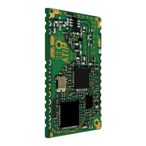
ATIM ARM-N8-LRW User manual

General information:
•Frequency: 868MHz, 915MHz
•LoRaWAN
•LoRa P2P
•Standalone
•RF data rate: 100 to 10000 bps
•Modulation: CSS
•Output power: 2 to 20 dBm
•Sensitivity: -142 dBm
•Link budget: 161dB
•Range up to: 25km
•Interface: UART
•Dimensions: 30mm x 18mm
•Certified: EN 300 220
•Operating temperature: -20°C /+85°C
Typical application:
•Internet Of Things (IoT)
•Environment
•Intelligent structures
•Telemetry
•Alarm and wireless security
systems
•M2M
•Remote sensors
USER GUIDE
Transceiver 868MHz : 14/20dBm
ARM-N8-LRW
MODULE

Document Information
File name
EN-UG -ARM-N8-LRW
Created
04/07/2018
Total pages
62
Version
Notes
Firmware supported
V1.1
First preliminary release (2018-07-04 TDX)
ARM-N8-LRW_3-2-3_ACW-RTU_v2-0-0_BL_ENC.bin
V1.2
Second preliminary release (2018-12-10 TDX)
ARM-N8-LRW_3-2-3_ACW-RTU_v2-0-0_BL_ENC.bin

ARMSE_MU2.0
ARM-N8LWR DS | ATIM
3
SUMMARY
1GENERAL DESCRIPTION...............................................................................................6
2Technical features ............................................................................................................7
2.1 BLOCK DIAGRAM .............................................................................................................7
2.2 Dimensions ........................................................................................................................7
2.3 Pinout .................................................................................................................................8
2.4 Electrical characteristics ....................................................................................................9
2.5 Link interfaces....................................................................................................................9
2.6 Power supply......................................................................................................................9
2.7 Impedance of the antenna MATCHING...........................................................................10
2.8 FOOTPRINT AND GROUND PLAN ................................................................................10
2.9 ELECTROSTATIC DISCHARGE.....................................................................................11
2.10 Material information .........................................................................................................11
2.11 RECOMMENDED SOLDERING REFLOW PROFILE.....................................................11
2.12 Moisture sensitivity...........................................................................................................12
3Overall organization........................................................................................................13
3.1 LoRa M2M........................................................................................................................13
3.2 LoRaWAN ........................................................................................................................13
3.3 Transparent UART/RF BRIDGE ......................................................................................13
3.4 Standalone mode.............................................................................................................13
3.5 COMMAND MODE ..........................................................................................................14
Distant .......................................................................................................................................................14
3.6 TEST MODE ....................................................................................................................14
4Device organization ........................................................................................................15
4.1 Memory ............................................................................................................................15
4.1.1 Memory footprint and buffers ......................................................................................................15
4.2 Registers ..........................................................................................................................16
4.2.1 Registers organization.................................................................................................................16
5Main parameters (LORA M2M & LORWAN)..................................................................18
5.1 UART................................................................................................................................18
5.1.1 AT commands .............................................................................................................................18
5.2 Transparent UART/RF BRIDGE ......................................................................................19
5.3 Low Power mode .............................................................................................................19
5.4 Delays ..............................................................................................................................21
5.5 Postamble ........................................................................................................................22
5.6 Led behavior ....................................................................................................................22
5.7 Test mode ........................................................................................................................22
5.7.1 Battery level (ATT08) ..................................................................................................................23

ARMSE_MU2.0
ARM-N8LWR DS | ATIM
4
RSSI reader (ATT09) ................................................................................................................................23
Continuous RSSI reader (ATT0A) ............................................................................................................23
5.7.2 Periodic emission (ATT0E)..........................................................................................................23
5.8 CONFIGURATION:..........................................................................................................24
6LoRaWAN.......................................................................................................................26
6.1 Generalities......................................................................................................................26
6.1.1 • Bidirectional endpoint (Class A):...............................................................................................27
6.1.2 • Bidirectional endpoint with programed receive windows (Class B):.........................................27
6.1.3 • Bidirectional endpoint with continuous reception (Class C): ....................................................27
6.2 Communication ................................................................................................................27
6.2.1 • UnConfirmed frame:..................................................................................................................27
6.2.2 • Confirmed frame:.......................................................................................................................27
6.3 Radio frequencies characteristics....................................................................................28
6.4 Radio................................................................................................................................28
6.4.1 Choosing the LoRaWAN class....................................................................................................28
6.5 Main parameters ..............................................................................................................28
6.5.1 OTAA process .............................................................................................................................30
6.5.2 Advanced parameters .................................................................................................................30
6.6 LoRaWAN parameters (Read only) .................................................................................34
6.7 Advanced options ............................................................................................................35
6.7.1 DL_REC functionnality ................................................................................................................35
6.7.2 EMIT_CYCLE functionnality........................................................................................................36
6.7.3 Alive frame...................................................................................................................................36
6.7.4 Logs.............................................................................................................................................37
6.7.5
Examples
.....................................................................................................................................37
7lora p2p...........................................................................................................................38
7.1 RF Specification...............................................................................................................38
7.1.1 REVERSAL TIME........................................................................................................................39
7.2 UART Configuration.........................................................................................................39
7.3 Serial buffers....................................................................................................................40
7.4 Transparent (SERIAL/RF BRIDGE).................................................................................42
7.4.1 Configuration ...............................................................................................................................42
7.4.2 Functioning ..................................................................................................................................42
VariablePacket..........................................................................................................................................43
7.5 MAIN PARAMETERS ......................................................................................................44
7.5.1 RF CONFIGURATION IN P2P MODE ........................................................................................44
7.5.2 Low Data Rate Optimization........................................................................................................45
7.6 LoRaTM Packet Structure................................................................................................46

ARMSE_MU2.0
ARM-N8LWR DS | ATIM
5
7.6.1 Preamble .....................................................................................................................................46
7.6.2 Variable packet LoRa-Header Mode...........................................................................................46
7.6.3 Fixed packet LoRa-Header Mode ...............................................................................................46
7.6.4 SyncWord ....................................................................................................................................47
7.6.5 Low Data Rate Optimization........................................................................................................47
7.6.6 Lora-Payload ...............................................................................................................................47
7.6.7 Address........................................................................................................................................48
7.6.8 User payload ...............................................................................................................................49
7.7 LBT (Listen Before Talk) ..................................................................................................49
7.8 LBT&AFA (Adaptative Frequency Agility)........................................................................50
Exemple :
..................................................................................................................................................50
7.9 SNIFF MODE ...................................................................................................................51
7.10 Repeater ..........................................................................................................................52
7.10.1 Unidirectional configuration:....................................................................................................52
7.10.2 Bidirectional configuration:......................................................................................................52
7.11 Description of the Registers.............................................................................................53
7.12 Radio channels ................................................................................................................54
7.13 test MODE........................................................................................................................56
7.13.1 PING PONG MODE: ...............................................................................................................56
7.13.2 RSSI READING: ATT0A/ATT02 OR ATS000=0A/ATS000=02..............................................57
7.13.3 PUR CARRIER MODE: ATT04 or ATS000=04 ......................................................................57
7.13.4 CONTINUOUS MODULATION: ATT07 or ATS000=07 .........................................................58
7.13.5 TRANSIENT MODE: ATT08 or ATS000=08...........................................................................58
7.14 EXAMPLE ........................................................................................................................59
7.14.1 RX MODE WITH RSSI READING ..........................................................................................59
7.14.2 ADRESS MODE......................................................................................................................59
7.14.3 REPEATER IN BIDIRECTIONAL CONFIGURATION+ADRESS MODE ...............................61

ARMSE_MU2.0
ARM-N8LWR DS | ATIM
6
1GENERAL DESCRIPTION
E
Figure 1
The N8-LRW is a radio module using LoRa modulation that guarantees high immunity to interference, and a very low
sensitivity in reception. These characteristics which make it possible to reach a very long range.
The N8-LRW is a dual-mode module, capable of working on both LoRaWAN and Lora M2M. It can be operated under M2M
or LoRaWAN modes, or under both modes simultaneously. Under LoRaWAN, the module can be used in either class A or
class C. Under Lora M2M, the module can be operated in ENSI or FCC.
The N8-LRW module is pin-to-pin compatible with other modules from ATIM. It has taken over all features of the ARM N8-
LW model. Other UART / BRIDGE mode, the N8-LRW embarks a so-called "Standalone" mode, enabling users to directly
connect it to sensors without going through an external microcontroller. You will find usage examples on a note app. The
Standalone mode allows for the integration of a new connected device in a very short time, even for users not familiar with
embedded programming. The Standalone mode can be used under both LoRaWAN and LoRa P2P.
LoRa : EU / FCC
LoRaWan : EU
Classe A,C
UART // RF BRIDGE
STANDALONE MODE
N8LRW

ARMSE_MU2.0
ARM-N8LWR DS | ATIM
7
2TECHNICAL FEATURES
2.1 BLOCK DIAGRAM
Figure 2: Module schematic
The N8-LRW module features very high RF performances. Thanks to very low noise level generated by the LNA component,
module’s sensitivity is -142dBm (BW = 125kHz, SF = 12), while most modules available on the market have a sensitivity of
-137dBm.
By using both the RF PA Boost output and the RF Out output of the SX1272, users will have the choice to operate at 20 or
14dBm without over-consumption.
2.2 DIMENSIONS
Module dimensions
Module footprint
Figure 3
All ARM-Nx-xxx modules are footprint compatible and share the same dimensions.
STM32L151CBU6
SX1272
LNA
RF SWITCH
RF FILTER
RF out
RF in
RF out 14dBm
RF PA boost 20dBm
30
18

ARMSE_MU2.0
ARM-N8LWR DS | ATIM
8
Figure 3 shows the ARM-N8-LWR module dimensions. Dimensions are in mm.
The N8-LRW has the same size as other models from ATIM range and keeps the compatibility of all the essential pins. By
choosing the footprint of the N8LRW, you can use any ATIM N8 module.
2.3 PINOUTS
Table 1 below describes pin allocation according to the layout on Figure 2. Some pins are currently reserved for future
development.
Table 1 pin allocation
Pin
Name
I/O
Function
1
AGND
-
Ground (1)
2
ANTENNA
I/O
RF signal
3
AGND
-
Ground (1)
4
GPIO0
O
STA_DO_0
5
GPIO1
O
STA _DO_1
6
AGND
-
Ground (1)
7
GPIO2
I
STA _CPT_0
8
GPIO3
I
STA
9
GPIO4
-
NC
10
GPIO5
-
NC
11
GPIO6
-
NC
12
GPIO7
-
NC
13
GPIO8
I
STA _ADC_0
14
DGND
-
Ground (1)
15
GPIO15
NC
16
GPIO16
NC
17
GPIO17
NC
18
DGND
-
Ground (1)
19
VDD
-
Power supply
20
WAKE-UP
I
Wake-up input
Can be NC if not used
21
GPIO9
I
STA _DI_1
22
GPIO10
I
DL_REC / RTU_ON
23
U1RX
I
RX UART
24
U1TX
O
TX UART
25
GPIO11
-
STA VSensEN
26
GPIO12
I
STA _DI_2
27
nReset
I
Hardware reset, active when set to GND
It is advised to be connected to VDD, can be NC if not used
28
AGND
-
Ground (1)
29
GPIO13
-
NC
30
GPIO14
O
STA _DO_2
31
AGND
-
Ground (1)
32
AGND
-
Ground (1)
STA:Standalone

ARMSE_MU2.0
ARM-N8LWR DS | ATIM
9
2.4 ELECTRICAL CHARACTERISTICS
Following values in table 2 have been measured on pre-series devices, and do not correspond to the series. They will be soon
updated to describe electrical characteristics of the series.
Table 2 : Electrical ratings
Min.
Typ.
Max.
Power Supply (Vdd)
3V
3.3V
3.6V
Consumption (Vdd = 3.3V)
Tx / 14dBm
45 mA
50 mA
56 mA
Tx / 20dBm
-
150
160
Rx
20 mA
22 mA
24 mA
Veille
0.5 µA
0.6 µA
0.9 µA
Input voltage
Gnd
-
0.2 xVdd
Output voltage
0.8 x Vdd
-
Vdd
2.5 LINK INTERFACES
▪UART 2 wires + flow control by RTS/CTS (1200 –230400 bps)
▪SPI Slave (≤2MHz)
▪1 wake up input
▪1 digital output « signalization »
▪1 analog output 12 bits (option)
▪functioning mode:
▪Transparent mode « UART/RF bridge » or « SPI/RF bridge »
▪Repeater mode M2M; M2M/LoRaWAN
▪Standalone mode
▪Configuration mode « AT » local and distant
▪Test modes: Ping-pong, pure carrier, continuous request, RSSI reading
2.6 POWER SUPPLY
The module’s power supply is between 2,7V and 3,6V. To ensure good filtering of power supply, the LC filter must be
positioned as close to the pin VDD as possible.
Figure 4: Power supply filter
GND
Vcc
68pF
100nF
100nH

ARMSE_MU2.0
ARM-N8LWR DS | ATIM
10
2.7 IMPEDANCE OF THE ANTENNA MATCHING
Passive components to be integrated between the antenna and the RF pin of ARM-Nx module depend on the length of the
electronic track, of the dielectric and of the chosen antenna. For a quick implementation, a 68pF serial condenser can be
used. Other components are optional and do not need to be wired.
It is important to keep these components in Pi to be able to modify impedances in case the antenna was not correctly
adapted.
Figure 5: Impedance matching
2.8 FOOTPRINT AND GROUND PLAN
It is recommended to cover the whole surface underneath ARM-Nx modules with a ground plan. This surface must be
varnished to avoid any short circuit. It is advised not to put any vias on this surface nor to use ovarnished vias.
68pF
NC
NC
50ohm line

ARMSE_MU2.0
ARM-N8LWR DS | ATIM
11
Figure 6: Footprint and ground plan
2.9 ELECTROSTATIC DISCHARGE
ARM-Nx modules are sensitive to electrostatic discharge and must be handled in accordance with JESD625-A.
Note: JEDEC standards are available free of charge on the JEDEC website http://www.jedec.org.
2.10 MATERIAL INFORMATION
This product is free of environmental hazardous substances and complies with 2002/95/EC. (RoHS directive).
RoHS documentation is available on request
Contact surface: gold over nickel
2.11 RECOMMENDED SOLDERING REFLOW PROFILE
Figure 7: Reflow profile
Notes:
oARM N8 should be soldered in upright soldering position.
oNever exceed maximum peak temperature
oReflow cycle allowance: 1 time
oThis device is not applicable for flow solder processing
oThis device is applicable for solder iron process with following soldering criteria:
▪Use solder iron at or below 350°C
▪Soldering time: < 3 sec.
▪Pause between two soldering points: 3 sec.

ARMSE_MU2.0
ARM-N8LWR DS | ATIM
12
2.12 MOISTURE SENSITIVITY
This device must be pre-baked before entering reflow soldering process. Disregarding this recommendation may cause
destructive effects, such as chip cracking, leaving the device non-functional!
Shelf life
6 months, sealed
Pre-baking recommendations
12 hrs. at 60°C
Floor life (time from pre-baking to soldering
process)
<72 hrs.

ARMSE_MU2.0
ARM-N8LWR DS | ATIM
13
3OVERALL ORGANIZATION
3.1 LORA M2M
LoRa M2M allows point-to-point or point-to-multipoint communication with a long range, ranging from 15km at 14dBm up
to 35km at 20dBm. In some situations, users have been able set a communication beyond 100km. It is possible to
significantly increase the range in constrained area by installing other modems as “signal repeaters”.
Unlike LoRaWAN mode, the M2M protocol allows for a device to operate in “sniff mode”in order to permanently listen
with ultra-low power consumption.
Configurations are essentially through ATM and ATS commands
3.2 LORAWAN
LoRaWAN is a telecommunication protocol that enables low-speed radio communication of low-power objects that
communicate using LoRa technology and connect to the network via gateways, thus contributing to the Internet of Things.
Configurations are essentially ATM and ATO commands
3.3 TRANSPARENT UART/RF BRIDGE
In this mode, incoming data on the Rx UART pin are packetized with LoRaWAN or Lora M2M headers in order to be sent by
radio. The payload received and available on the gateways or on a other device is the same as the previous one entering
UART.
3.4 STANDALONE MODE
Stand Alone mode allows a user who has no knowledge of embedded electronics to design an IOT product in the shortest
time. It works in LoRa M2M and MoRa M2M. The module has many inputs and outputs that can be modified by AT
commands in UART, or by the graphical configurator. This mode allows users to make sensors extremely fast.
Configurations are essentially ATO commands
It gives users control on:
•3 Digital Inputs (DI)
•1 Counter (CPT)
•1 Analog Input (ADC)
•3 Digital Outputs (DO)
•1 Sensor Power Enable
DIGITAL
OUTPUT
0
DIGITAL
OUTPUT
1
DIGITAL
OUTPUT
2
DIGITAL
INPUT 2
DIGITAL
INPUT 1
DIGITAL
INPUT 0
COUNTE
R
ANALOG
INPUT
VsensEN

ARMSE_MU2.0
ARM-N8LWR DS | ATIM
14
For advance details on this mode consult the application note ATIM_ARM-N8-LW_AN-RTU_EN.
3.5 COMMAND MODE
Local
Entering command mode can be done in two ways:
1Sending three ‘+’ characters consecutively when the device is in normal mode. This method will send the two first
characters by radio.
2Sending three ‘+’ characters in one frame when the device is in normal mode. This method does not send the first
two characters by radio.
Once in this mode, every data entering the UART will be considered to be an AT command.
Distant
In LoRaWAN very data received on port 160 will be considered to be an AT command. They must have the same format as
those sent by serial. Do not forget to send end of line ‘\r’ and/or ‘\n’ at the end of the command. Parameters used are
LoRaWANs.
Example:
To send the command ATV to the module by downlink, the payload need to be 0x4154560d
3.6 TEST MODE
Cf 5.7

ARMSE_MU2.0
ARM-N8LWR DS | ATIM
15
4DEVICE ORGANIZATION
4.1 MEMORY
There are three different memories, the RAM, the EEPROM and the Flash.
The parameters that are used by the device are stored in the RAM. Access is faster, but everything is lost when switched
off. It is used by the device to store parameters when running.
EEPROM as a slower access but is able to keep parameters even after it is switched off. It is used to store
parameters/configuration for the device.
The Flash is a read only memory. It’s used to store firmware and factory configuration to restore parameters if needed.
4.1.1 Memory footprint and buffers
Table 3 display the global memory organization.
Table 3: Global memory organization
Function
Memory type
Capacity (Bytes)
Firmware
Flash
64k
AT parameters saved (ATM, ATO, IDs)
EEPROM
-
AT parameters in use (ATM, ATO, IDs)
RAM
-
Buffer UART Rx
RAM
256
Buffer UART Tx
RAM
256
Buffer Radio Rx
RAM
256
Buffer Radio Tx
RAM
256
Buffer command mode Rx
RAM
128
Buffer command mode Tx
RAM
256
Every data entering the Rx Uart will be redirected into buffer corresponding to the current mode, Tx Radio or Rx AT.
Every data received by radio (Rx Radio) and coming from the command mode (Tx AT) will be redirected on the Tx Uart.
Uart Rx buffer can accept up to 256 Bytes. If user overflow the buffer, there will be data lost. Data flow control CTS/RTS
should be implemented in a future version.
Radio Tx buffer can stack up to 32 messages for a maximum size of 256 Bytes (sum of every messages). If user overflow
one of them, there will be data lost. This issue will be corrected in a future version.
AT Rx can only stack one AT command at the time, up to 128 Bytes. If an AT command arrive while the operation of the
previous one is not done yet, the last one entered will be lost.

ARMSE_MU2.0
ARM-N8LWR DS | ATIM
16
4.2 REGISTERS
There are three main structures of data in memory: the device configuration, user parameters, and the IDs.
The device configuration is accessible in Read/Write by ATM command (M). It is mainly used to store device
configuration, like parameters defining if it’s configured to use LoRa or LoRaWAN radio, to choose the LoRaWAN class,
to configure UART transmission, etc.
User parameters are accessible in Read/Write by ATO command from 75 to 96 (O Param). Mainly used to configure
radio parameters like spreading factor, emission power, channel, and activate Rx windows, ADR, duty cyle, etc.
IDs are accessible in read only by ATO command from 0 to 74 (O IDs).
4.2.1 Registers organization
The memory footprint is visible in the Figure 8. It explains how all the structures are stored, and how they can be
accessed.
MATF
ATF
M M
O ParamO Param O Param
O IDsO IDs
Boot
Boot
Boot
ATMX=Y
If ATM1(_WriteIn) == RAM
If ATM1(_WriteIn) == EEPROM
RAM EEPROM FLASH
ATOX=Y
Figure 8: Memory access and organization
The device uses RAM structure.
EEPROM structures are used to store user configuration. They are loaded in RAM structure each time the device boots
up. Therefore, EEPROM structures are used to initialize and configure the device at every boot.
The structures can be accessed with AT commands
An ATM command will change the corresponding parameter value in the RAM structure. ATMS command is the only
way to save this structure in EEPROM
An ATO command will change the corresponding parameter value in the RAM structure. ATOS command is the only
way to save this structure in EEPROM

ARMSE_MU2.0
ARM-N8LWR DS | ATIM
17
Factory settings can be restored with ATF command; it will load EEPROM structure with the one configured in Flash.
IDs aren’t changed by this command.
User can restore EEPROM structure in RAM, or save the RAM structure in EEPROM with command ATMS, ATMR, ATOS
and ATOR. It allows to test a configuration, change RAM values and saving it after in EEPROM all parameters at once,
or restoring EEPROM configuration if needed.

ARMSE_MU2.0
ARM-N8LWR DS | ATIM
18
5MAIN PARAMETERS (LORA M2M & LORWAN)
5.1 UART
UART communication can be configured with ATM command from 007 to 012. It is important not to forget to save the
configuration entered with ATMS command.
There is two ways to apply modifications. The first one is to use the command ATIU to only reset the UART. The second one
is to reset the module Reset, it can be hardware or software via the command ATR.
Table 4: Uart configuration, AT commands
ATM
Bit
Parameter
Register value
007
0:7
Baudrate UART
600 bps = 0x00,
1200 bps = 0x01,
2400 bps = 0x02,
4800 bps = 0x03,
9600 bps = 0x04,
14400 bps = 0x05,
19200 bps = 0x06,
38400 bps = 0x07,
56000 bps = 0x08,
57600 bps = 0x09
008
0:7
Wordlength
0x00: 8 bits,
0x01: 9 bits
009
0:7
Parity
0x00: no parity,
0x01: even parity,
0x02: odd parity
010
0:7
Stop bits
0x00: 1 stop bit,
0x01: 0.5 stop bit,
0x02: 2 stop bit,
0x03: 1.5 stop bit
011
0:7
Flow control
0x00: no flow control,
0x01: rts flow control,
0x02: cts flow control,
0x03: rts/cts flow control
012
0:7
Timeout char
0xMM: 0xMM char to wait for timeout
5.1.1 AT commands
Table 5 :AT commands
Command
Function
+++
Enter in AT command mode. (IN SERIAL ONLY)
$$$
Enter in AT command mode. (IN OTA ONLY)
ATQ + ENTER
Exit AT command mode.
ATR + ENTER
Reset MCU.
ATM'XXX' + ENTER
Read MXXX register,
XXX decimal value.
ATM'XXX'='YY' + ENTER
Write MXXX register,
XXX decimal value,
YY hexadecimal value,
Write in RAM structure.
ATMS + ENTER
Save ATM structure from RAM to EEPROM.

ARMSE_MU2.0
ARM-N8LWR DS | ATIM
19
Command
Function
ATMR + ENTER
Restore ATM structure from EEPROM to RAM.
ATO'XXX' + ENTER
Read OXXX register,
XXX decimal value.
ATO'XXX'='YY' + ENTER
Write OXXX register,
XXX decimal value,
YY hexadecimal value,
Write in RAM structure.
ATOS + ENTER
Save ATO user parameters structure from RAM to EEPROM.
ATOR + ENTER
Restore ATO user parameters structure from EEPROM to RAM.
ATOI + ENTER
Save IDs structure from RAM to EEPROM.
ATF + ENTER
Restore factory parameters for ATM and ATO structure.
Does not change IDs.
It is best to restart module with ATR or by hardware connection for some parameters to
take effect, (eg: module configuration)
ATV + ENTER
Return module type, firmware revision, radio band used, DevEUI (LSB first) and LoRaWAN
version.
ATVV + ENTER
Return ATV and old firmware revision format.
ATL’XXX’ + ENTER
List parameters for a structure.
XXX can be:
O to list ATO user parameters structure and IDs,
M to list ATM structure,
ATT’XX’ + ENTER
Launch test mode XX,
XX hexadecimal value.
AT$SB=’X’ + ENTER
Send X as a frame,
X can be 0 or 1.
AT$SF=’XXX’ + ENTER
Send XXX as a frame, XXX can be the size of a normal frame.
ATI’X’ + ENTER
‘X’ can be
B to empty all buffers; all data are lost,
U to restart Uart, apply configuration bytes changes,
R to restart radio layer, apply configuration bytes changes, resets data.
5.2 TRANSPARENT UART/RF BRIDGE
In this mode, incoming data on the Rx UART pin are packetized with LoRaWAN or Lora M2M headers in order to be sent by
radio. The payload received and available on the gateways or on a other device is the same as the previous one entering
UART.
5.3 LOW POWER MODE
Low power mode is used to achieve the lowest power consumption possible. When it is sleeping the device cannot be
accessed in any way, it has to be woken up before.
When the mode Low Power is on, it can be configured to be controlled with the Wake Up pin or the Uart Rx pin.
A quick summary of these modes is displayed in Table 6. Further details are in followings parts 0 page 20, and 0 page
21.
Table 6: Low Power mode summary
Wake up configured on:
Wake Up pin
Uart Rx pin
Waking up if:
Device is sleeping and there is a
rising edge on the Wake Up Pin.
Device is sleeping and there is a
falling edge on Uart Rx Pin
Waking up time
Min 13 ms, typical 15 ms

ARMSE_MU2.0
ARM-N8LWR DS | ATIM
20
‘0’ = Sleep
‘1’ = Awaken
AGND
ANTENNA
AGND
AGND
SOSC1
SOSC0
SDI2
SCS
SDO2
SCK2
SMSG
DGND
AGND
AGND
AGND
RESET MCU
AN0
RSSI
U1TX
U1RX
U1RTS
U1CTS
INT0
VDD
DGND
GND
VDD
ou
VBAT
GND
GND
GND
Char IN
Stay awake if:
Wake Up pin set to ‘1’ or
something to do1.
Something to do.
Go to sleep if:
If Wake Up pin set to ‘0’ and
nothing to do2for 10 ms.
If nothing to do for 100 ms.
It is important to know that the device will finish his emission cycle Tx/Rx before going to sleep.
WAKING SOURCE: WAKEUP PIN
When the mode Low Power is on and configured to be controlled with the Wake Up pin, it responds to the following
cycle.
If the WakeUp pin is set to ‘1’ the device will stay awake.
If the WakeUp pin is set to ‘0’ the device will go to sleep after 10 ms without actions.
If there is a rising edge and the device is sleeping, it will awake.
If there is a rising edge and the device is running, it will continue running.
Figure 10: Timing for Low Power On, programmed to wake up on wake up pin
Figure 10 shows a chronogram of the device state when configured to wake up on the Wake Up pin.
The device will go in sleep mode after 10 ms without any actions (eg: 2*).
When sleeping, it will be awaken by rising edge on the Wake Up pin (eg: 1*).
1
Something to do: The device has something to do when it is in command mode or it has an emission
cycle running or there is undealt data in a buffer.
2
Nothing to do: The device has nothing to do when it is not in command mode and it has no running
emission cycle and every buffers are empty (every data has been dealt with).
Figure 9
Table of contents
Other ATIM Transceiver manuals
Popular Transceiver manuals by other brands

Chamberlain
Chamberlain EASRM 001D9526-12 user manual

ComNav
ComNav Class B AIS Installation & operation manual

Satworx
Satworx Iridium extreme quick start guide

Becker
Becker AR6201 Series Installation and operation

PC Electronics
PC Electronics tc70-20 user manual

YEONHWA M TECH
YEONHWA M TECH XRadio XR Series user manual

BWI Eagle
BWI Eagle AIR-EAGLE XLT PLUS 461-40800-AC manual

Siemens
Siemens 563-056 installation instructions

Icom
Icom IC-02N instruction manual

Jupiter Avionics
Jupiter Avionics JA33-001 Installation and operating manual

Stryker
Stryker SR-655HPC user manual

Chongqing Xiegu Technology
Chongqing Xiegu Technology X1M manual