1.4 Operation principle
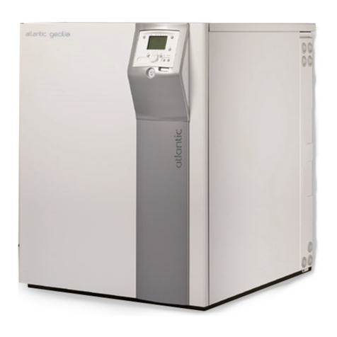
The ground source heat pump uses the energy stored
in rock, ground or water to provide heat to a building
and to sanitary water.
A ground source heat pump is made of 3 main
components:
- The heat pump itself,
- The brine circuit,
- The heating emitters (radiators, heating floor…).
• In the brine circuit: energy is taken from the rock,
ground or water by the brine and then released to
the refrigerant circuit. Brine circuit can be a surface
collector or several bore holes collector.
• The heat pump is made of a refrigerant circuit (ref. 1,
figure 4, page 7) which contains the following
components :
- Evaporator (ref. Ev, figure 7, page 9) : The heat
removed from the ground by the brine is released to
the refrigerant. Refrigerant boiling point is lower than
the brine temperature, the refrigerant moves from
liquid to gaseous states.
- Compressor (ref. Cp, figure 7, page 9) : Pressure
and temperature of the refrigerant are increased.
- Condenser (ref. Cn, figure 7, page 9) : The
refrigerant releases its energy to the heating circuit water.
The refrigerant moves from gaseous to liquid states.
- Expansion valve (ref. Dt, figure 7, page 9) :
Pressure and temperature of the refrigerant are lowered.
• The heat pump is equipped with a control system that
set the heating circuit water temperature according
to outdoor temperature. (heating curves). Room
sensor (optional) can be installed; it corrects the water
temperature according to indoor temperature when
needed.
• The heat pump is equipped with a back-up heater that
provides additional heat when needed.
• The heat pump, as an option, can be ducted to a boiler
which will provide the additional heat when needed.
• Control system function
- The average leaving water temperature of the heating
circuit is controlled by the heating curve.
- Indoor temperature can be scheduled (week/day),
several temperatures can be set.
- Switching from winter/summer operation modes is
automatic.
- Management of back up heater
- Management of ducted boiler* (optional)
- Room sensor*: corrective action on heating curve.
- 2nd heating circuit control
- Domestic hot water: heating schedule, management
of DHW circulating pump.
-Buffer tank* control (mandatory with radiators or
several heating zones / 15l/kW).
*in case heat pump is equipped with the correct option or kit.
• Fan-coil with integrated control system
Do not use a room sensor in the area equipped with fan
coils.
• Protection functions
- Anti-legionella cycle for domestic hot water*.
- Anti-freeze protection: when leaving water temperature
of the heating circuit reaches 5°C, anti-freeze
protection is activated (provided power supply is on).
• Domestic hot water (DHW) operation*
2 DHW temperatures can be set : nominal temperature
(line 1610, 55°C) and reduced temperature (line 1612,
40°C).
Factory schedule for DHW operation (lines 560, 561, 562)
set nominal temperature from 0:00 to 5:00 and from 14:30
to 17:00. Reduced temperature is set the rest of the day.
This schedule optimises the electrical energy consumption
and insures hot water availability and heating comfort.
Setting of reduced temperature can be useful to provide
often witch on of the DHW production.
DHW production is activated when DHW temperature is
12°C below the set temperature.
DHW heating can be completed by water tank back-up
heater when needed.
To insure DHW temperature higher than 45°C, it is
necessary to connect water tank back up heater.
Depending on the DHW schedule (line 1620), comfort
temperature will be maintained 24h/day or only during the
night or as defined in the schedule.
DHW production takes priority over heating. Nevertheless,
in case of simultaneous demand for DHW and heating,
the control system manages both heating times to insure
comfort.
A function to switch from “reduced” to “comfort” is available
on the user interface (see ref. 8, figure 23, page 28).
Anti-legionella cycles can be scheduled.
1.5 Performances
1.5.1 Running-in period
Compressor needs a running-in period.
Rating performances will be reached after a minimum of
48 hours running operation.
1.5.2 Expansion valve setting
Your appliance has been factory set to insure safe
operation and optimum performance
Interventions on refrigerant load or expansion valve
setting could be authorised only in case of extremely
stable hot or cold sources and under manufacturer
control.
Do not proceed to any changes without
agreement from manufacturer. Any mishandling
can cause serious damages.
Installation and operating manual "1641 - EN"
Ground source heat pump atlantic geolia 13 - 17
- 8 -
