ATLAS North AmericaProprietary
Sea Scan ARC Scout MKIIInstallation Guide 1 of 1
Page:7
Issue:1.1.0 SCTM2-INST
Installation Manual
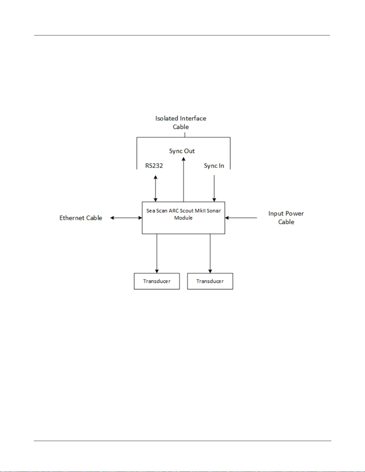
5 System Installation Guidelines
External Interference:
Our system is designedto amplify very small electrical signals and display them. Unfortunately, other
sources of electrical signalscanbe amplified and interfere with the image quality. These noise sources
needto be handledproperly toreduce theiraffectonthe system.
Typical noise sourcesinclude (butare not limitedto):
·Radiated(RF)
·Powersupply ripple
·Common mode ripple
The SeaScanARCScout MkII has been designedwithextensive shielding and filteringtominimize the
effectthatnoise sourceshave on the system'sperformance. Properplacement in the vehicle will further
reduce theireffect on the system'sperformance. In mostsystems,the SeaScanARC ScoutMkIIis installed
inthe main dry-housingalong with the sonarcomputer.Tohelppreventradiatedelectrical noise from
affecting the sonardata, itis best to keepthem asfaraway from otherelectronics aspossible. Typically, the
electronicshave been installedonthe back-side of theirgrounded chassis to help shieldthem fromother
active electronicnoise sources.
Ournewesttransducers/electronicshave alimitonthe distance fromthe transducerelectronics tothe
transducerof ~2meters.If longerdistances are required, the system will still operate but the performance
may be degraded.
Guide Lines:
·Avoidplacingthe SeaScanARCScoutMkIInearany active electronicdevicessuchasDC-DCconvertersor
othersonartransmitters as thismay cause noise tobe introduced.
·Donotroute any powerwiring, particularly input and/or output connections to DC-DCconverters, close
tothe SeaScanARCScoutMkII, the TransducerExtensionCable, orthe Transducers.
·KeepTransducerExtensionCable lengths to aminimum toimprove the signal to noise ratio.
·Connectall powerinput leads onthe powersupply as this is required for proper operation.
Do not transmit without transducers connected to the Sea Scan ARC Scout MkII as this may
damage the electronics.
Thermal Management
The SeaScanARCScoutMkII systemisequipped withinternal heatsinksthattransferthermal energy tothe
outerenclosure (primarilytothe mountingsurface). Formaximumperformance itisrecommendedthat
the systemisinstalled onanadequate thermal interface (generallyanaluminum chassis plate issufficient).
Anoptional coolingfanisavailable whenthe thermal interface isnotadequate orthe ambient
temperature iselevated. The systemhasautomaticthermal monitoringandmanagement capabilitiesand
will maintain the properoperatingtemperature through the adjustmentof the transmitdutycycle.
However,reducingthe dutycycle may resultinareductionof the transmitpulse strength.