Atlas Lighting Products ORIGIN ORWPL10L4K User manual

PO BOX 2348 • BURLINGTON, NC 27216 • 800-849-8485 • FAX: 1-855-847-2794
Electrical Specications
• Input Wattage: 99W
• Efcacy:157LpW
• AC Input: 120/208/240/277 V
•Driver:Constantcurrent,Class2,
120-277VAC 50/60Hz
Lighting Specications
• TotalLumens:15,536
• ColorTemperature:4000K
• ColorRenderingIndex:70
Housing Specications
• Die-castaluminumhousing
• UVstabilizedpowercoatednish
• Color:Bronze
• Lifespan:50,000hours
Lens Specications
• Borosilicateglasslens
Listings
• UL/cULstandardsforwetlocations
• DLCPremiumqualiedluminaire,
eligibleforrebatesfromDLC
memberutilities.
DLCProd.ID:PLKAH1T6BARF
Warranty
• 5-Yearlimitedwarranty
Model Watts Lumens Volts Color
Temp.
ORWPL10L4K 99 LED 15,536 120-277 4000K
PROJECT INFORMATION
MODEL #: ORWPL10L4K
UPC #:: 765364023910
Large Wall Pack
Photometrics
LightLoss
Factor 1.00
Total
Lumens 15536
Mounting
Height 18′
Max.
Calculated
Value
11.20Fc
18'18'
18'
0'
0'
36'36'
36'
54'54'
54'
72'
90'
10
2
.5
1
.2
.1
5
Mnt.Ht:18′
PO BOX 2348 • BURLINGTON, NC 27216 • 800-849-8485 • FAX: 1-855-847-2794
PROJECT INFORMATION
MODEL #: ORWPL10L4K
UPC #:: 765364023910
Large Wall Pack
LED Wall Pack
ORWPL Series
Installation
Guide
Origin by Atlas Lighting | 1406 S. Mebane St. | Burlington, NC 27215 | 800-849-8485 | www.originledlighting.com
Tools Required:
¼” bit driver
Electric Drill
Drill Bit Set
Wire Strippers
Wire Cutters
1. Before starting ensure that the power is disconnected.
2. Unpack fixture and ensure that there are no damaged parts.
3. This fixture is intended to be mounted on a vertical wall.
4. Open the fixture by removing the 2 tamper proof screws on
the front frame assembly.
5. Remove the frame assembly by sliding sideways off the hinge pins.
6. Prepare the back plate for mounting by drilling or knocking the
appropriate holes.
7. Line up the back plate in the desired location and mount securely.
8. If using a junction box, bring the branch circuit wire through the
knocked-out hole in the rear of the fixture.
9. If using an electrical conduit, remove the screw cap from the
desired conduit hole and replace with conduit pipe.
10. Connect the power leads with the included wire nuts as seen below.
Black to Black (Hot), White to White (Neutral), Green to
Green (Ground).
11. Reattach the front frame and glass LED assembly using the tamper
proof screws.
IMPORTANT
To weather-proof the installation use silicone sealant to seal all the
holes in the fixture housing, electrical connections, and all edges
between the fixture housing and the mounting surface.
A: 5/16” dia. Knockouts
B: 5/32” dia. Knockouts
C:1/2” NPS tapped holes
LED Driver
LINE
NEUTRAL
RED
BLACK
V+
V-
Wiring Diagram
BLACK/BROWN
WHITE/BLUE
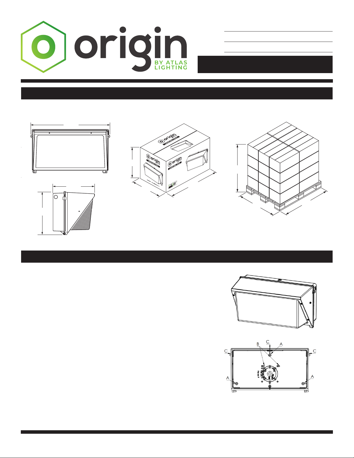
11.8"
11.42" 19.69"
Pallet DimensionsProduct Dimensions Carton Dimensions
Installation
Dimensions
Weight:14.9lbs.
1. Before starting ensure that the power is disconnected.
2. Unpack xture and ensure that there are no damaged parts.
3. This xture is intended to be mounted on a vertical wall.
4. Open the xture by removing the 2 tamper proof screws on the front frame
assembly.
5. Remove the frame assembly by sliding sideways off the hinge pins.
6. Prepare the back plate for mounting by drilling or knocking the appropriate holes.
7. Line up the back plate in the desired location and mount securely.
8. If using a junction box, bring the branch circuit wire through the knocked-out hole in
the rear of the xture.
9. If using an electrical conduit, remove the screw cap from the desired conduit hole
and replace with conduit pipe.
10. Connect the power leads with the included wire nuts as seen below. Black to
Black (Hot), White to White (Neutral), Green to Green (Ground) .
11. Reattach the front frame and glass LED assembly using the tamper proof screws.
Qty:40
50.93″
42″48″
18"
9.37"
9.84"
This manual suits for next models
1
Table of contents


