Solid Apollo NeonMax 24V 85W User manual

PRODUCT MANUAL
NeonMax 24V 85W Toll Free. 425-582-7533
www.SolidApollo.com
Andrew@SolidApollo.com
page 1
™
Product Description
Product Features
NeonMax 24V 85W
Thank you for purchasing Solid Apollo’s NeonMax 24V 85W!
Solid Apollo’s NeonMax is a state of the art Neon LED light simulating
the eect and look of neon in a continuous well-balanced light. This next
generation bendable NeonMax projects a brutally bright light oering
optimum performance, energy eciency, and eortless maintenance
over traditional glass neon.
This user guide is intended to instruct and guide any user on how to
properly cut the NeonMax to length, re-power with a new power cable,
and completely waterproof the connection.
• 20ft Spool
• Flexible & Cuttable
• Side Bending
• Cut Points Every 2in
• Fully Dimmable
• Features a 6.6ft Waterproof Cable w/ Female Barrel Connector
• Low Voltage Product at 24V - 85W Per Spool
• FullyWaterproof, Rated at IP67
• Indoor / Outdoor Application
• Product Comes Ready to Plug & Play
• Perfect for Accent Lighting, Linear Lighting and In-Wall Lighting
• Proper Cutting and Installation
• Waterproong and
Conguration Process
• Technical Information
• Do’s and Don’ts
Manual Will Review

PRODUCT MANUAL
NeonMax 24V 85W Toll Free. 425-582-7533
www.SolidApollo.com
Andrew@SolidApollo.com
page 2
™
Proper Cutting and Installation
Figure 1.
Tools & Accessories Required
This section will guide you on how to cut the NeonMax, install a power/extension cable, and add an end cap for a complete, fully
waterproof connection. Please note, for outdoor or high humidity applications, we recommend using waterproong glue for all
connections and a drying time of at least 24 hours before installing or using the NeonMax.
Sharp Metal Scissors or Shears (for cutting Neon at cut points)
5g Waterproong Glue
Soldering Iron
15ft Waterproof LED Strip Extension Cable
Cable End Cap for NeonMax 24V 85W
Box Knife or Blade
Look on both sides of the NeonMax strip and nd the side that has a thin transparent
line in the middle of the strip. The transparent line will be your guide to locating the
strip’s cut points.
Within the transparent lines you will see a distinctive small black line.That black line
is your cut point (see Figure 1).
Pro Tip: The NeonMax has cut points every 2 inches. If you are having a hard time
seeing the Cut Points, measure 2 inches from the beginning of the Neon Strip, mark it
with a marker and cut it from there.
Imagine a line passing from one side of the NeonMax to the other with the center being
the cut point symbol.Take either scissors or shears and line them up over the cut point
as straight as you can and cut through the NeonMax (see Figure 2).
Step 1: Locate the Cut Points
Step 2: Cutting the Cut Point
Figure 2.
PRODUCT MANUAL
NeonMax 24V 85W Toll Free. 425-582-7533
www.SolidApollo.com
Andrew@SolidApollo.com
page 3
™
Once you have made your cut, notice that the positive and negative contacts are tucked
inside the NeonMax Strip. Grab your box knife or blade and prepare to trim.
To gain access to the positive and negative contacts, you will need to cut 1/16 of an
inch o the NeonMax’s sleeve or just enough until you can clearly see the positive and
negative icons next to the contacts (see Figure 3).
Please Note: Be very careful when trimming o the sleeve. Do not cut all the way
through to the strip. The NeonMax’s sleeve is super soft and will only require the tip of
the blade.
Step 3: Exposing the Positive and Negative Contacts
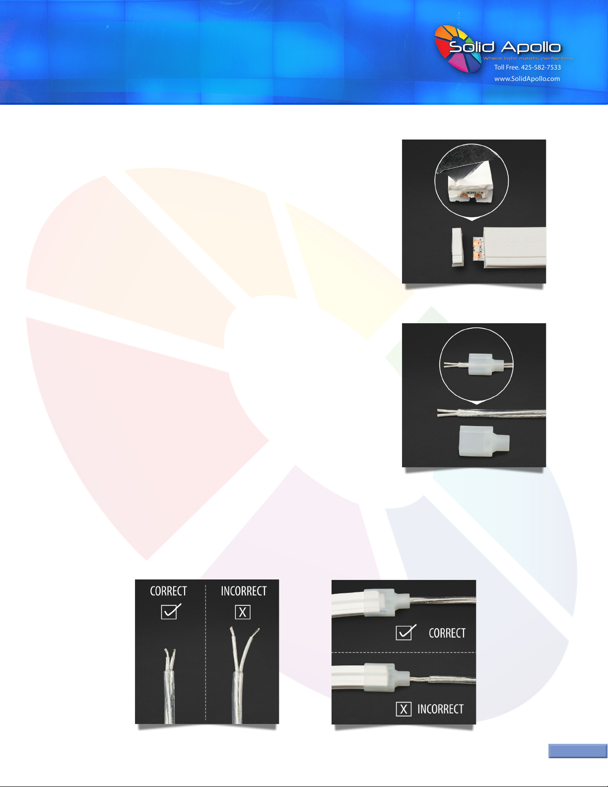
Step 4 is one of the most important steps in the guide as it is the easiest to forget. Slide
the Cable End Cap on to the cable wire before proceeding to the next step (see Figure 4).
Failure to do this step will cause you to re-do the soldering process.
Step 4: Insert Cable End Cap to Cable Wire
When splicing your Waterproof Cable wires, be sure to cut the positive and negative wires as short as 1/8 of an inch or short enough for the main
waterproof cable to be inside the Cable End Cap (see Figure 5). Leaving the positive and negative wires too long will not properly seal the connection and
will cause the NeonMax to fail over time due to debris and exposure to other damaging elements. See Figure 6 for proper connection.
Step 5: Splicing Waterproof Cable Wires
Figure 3.
Figure 4.
Figure 5. Figure 6.
PRODUCT MANUAL
NeonMax 24V 85W Toll Free. 425-582-7533
www.SolidApollo.com
Andrew@SolidApollo.com
page 4
™
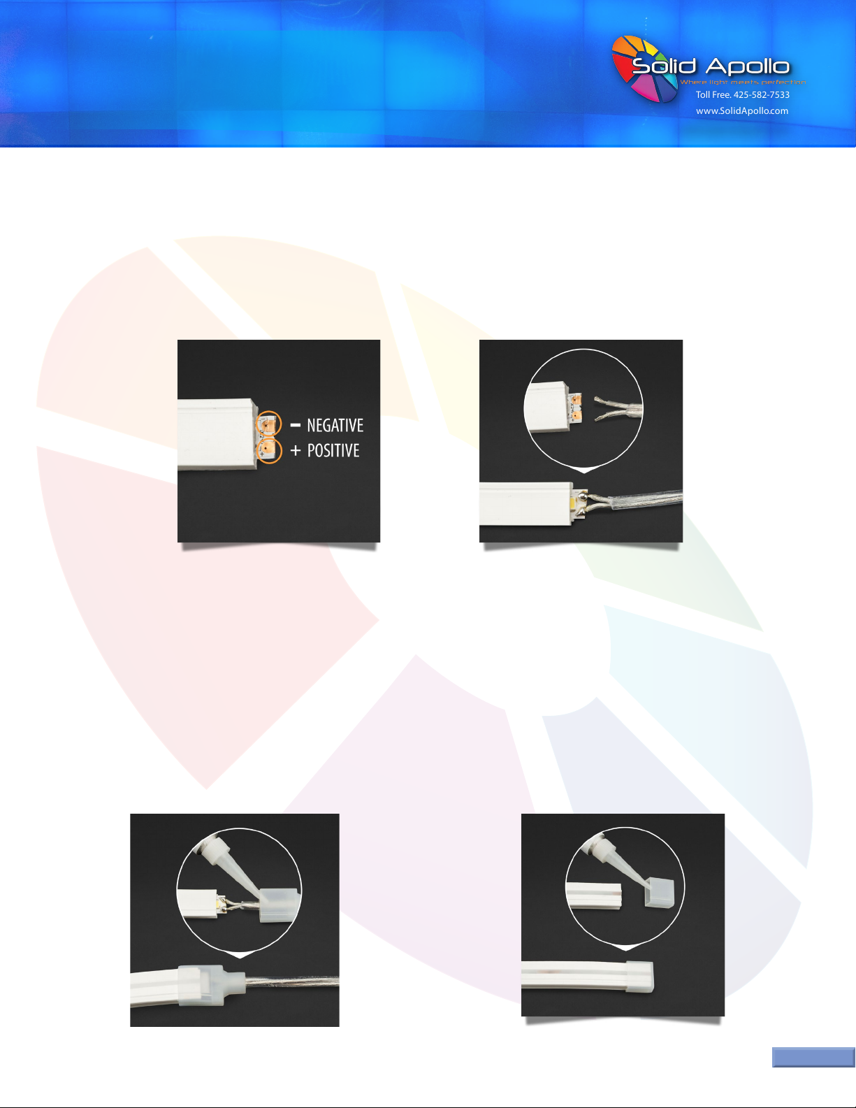
If you are using standard power cables (red and black wires) keep in mind which contact is positive and negative when soldering your connections. On
the strip, you can identify which side is positive or negative by looking for the icons corresponding to positive and negative (see Figure 7). Depending on
the model of the strip the positive may be on top with negative on bottom or vice versa.
The example shown in Figure 8 utilizes Solid Apollo’s 15ft Waterproof Cable which has a white strip running along the positive wire as an identier.
When using a similar cable with a barrel connector, double check you’re connecting the positive wire to the positive contact and the negative wire to the
negative contact to avoid a short circuit or having to re-solder.
Step 6: Soldering Positive and Negative Wires
Figure 7. Figure 8.
Before completing a waterproof seal, check rst to see if your
connections work. Once you’ve conrmed the strip properly lights,
put a pinch of the 5g Waterproong glue inside the Cable End Cap
(Figure 9). Slide the end cap over the connection and the beginning
of the strip until it’s snug and you’re good to go.
Please note: Let the unit dry for at least 24 hours before
installing or using the NeonMax.
Like Step 7, check rst to see if your connections work. Once you’ve
conrmed the strip properly lights, put a pinch of the 5g Waterproong
glue inside the End Cap (Figure 10). Slide the end cap over the end of
the strip until it’s snug and you’re good to go.
Please note: Let the unit dry for at least 24 hours before installing or
using the NeonMax.
Step 7: Waterproof Seal - Cable End Cap Step 8: Waterproof Seal - End Cap
Figure 9. Figure 10.

PRODUCT MANUAL
NeonMax 24V 85W Toll Free. 425-582-7533
www.SolidApollo.com
Andrew@SolidApollo.com
page 5
™
Technical Information
1. Do - Check the length of the positive and negative wires before soldering to avoid having to cut and re-solder the cables.
Remember, if the cables are not a proper length the connection will not be waterproof sealed.
2. Don’t - Do not forget to slide the Cable End Cap onto the cable wire rst before soldering your connections (refer to Step 4).
Do’s and Don’ts
Before Soldering Cable Wires to NeonMax
Proper Handling and Cutting
1. Do - Always double-check the cut point you are preparing to cut. Highlight it with a marker if you have to, it’s better
to be safe than sorry.
2. Don’t - Keep in mind that the NeonMax is side bending (left to right) in the opposite direction of the light output
and not top bending (up and down). Bending the NeonMax vertically could split the contacts causing the unit to fail.
If you do have to adjust the NeonMax vertically, o the brackets for example, pull the unit o the brackets gently.
Dimmable :
Minimum Cut :
Available Colors :
Total LEDs :
LEDs per Foot :
Operating Voltage :
Watts per Foot :
Candle Light Warm White 2400K
Super Warm White 2700K
Warm White 3000K
Daylight White 4000K
Natural White 5000K
Red, Green, Blue, & Amber
Yes
2in (50mm)
720
37
24V
4.3W
Watts per Spool :
Max Power :
LED Type :
Beam Angle :
Warranty :
Weight :
Size :
IP Rating :
Working Temperature :
85W
85W
SMD 2835
113º
3 Years
3.6lb
L: 19.7ft x W: 0.4in x H: 0.72in
IP67
-10F to 140F
Table of contents
Other Solid Apollo Lighting Equipment manuals


Popular Lighting Equipment manuals by other brands


IN HOUSE LED
IN HOUSE LED HUB-RD-PIR user manuel

Chauvet
Chauvet Colorado 1 Tri IP user manual

ETI Solid State Lighting
ETI Solid State Lighting 53508101 Use and care guide

Osram
Osram LEDambient LEDINT203 quick start guide

LDR
LDR Astro 100CM RGBW operating instructions

Metalumen
Metalumen RAIL 4 installation instructions