Atlas Scientific EZO-ORP User manual

Range -1019.9mV − 1019.9mV
1 reading per sec
Response time
+/– 1mV
Accuracy
Any type & brand
Supported probes
Single pointCalibration
UART & I2CData protocol
98 (0x62)
Default I2C address
3.3V − 5V
Operating voltage
ASCII
Data format
N/ATemp compensation
Reads ORP
EZO-ORP™
Embedded ORP Circuit
V 4.8
Revised 8/13/19
This is an evolving document, check back for updates.
Written by Jordan Press
Designed by Noah Press
PATENT PROTECTED

This is sensitive electronic equipment. Get this device working in
a solderless breadboard first. Once this device has been soldered
it is no longer covered by our warranty.
This device has been designed to be soldered and can be soldered
at any time. Once that decision has been made, Atlas Scientific no
longer assumes responsibility for the device’s continued operation.
The embedded systems engineer is now the responsible party.
Get this device working in a
solderless breadboard first!
Do not embed this device without
testing it in a solderless breadboard!
1
5
10
15
20
25
30
1
5
10
15
20
25
30
A
B
C
D
E
F
G
H
I
J
A
B
C
D
E
F
G
H
I
J
r 0.1

UART I2C
Circuit dimensions
Power consumption
Absolute max ratings
Operating principle
Power and data isolation
Correct wiring
Calibration theory
Default state
Available data protocols
Circuit footprint
Datasheet change log
Warranty
UART mode
Receiving data from device
Sending commands to device
LED color definition
UART quick command page
LED control
Find
Continuous reading mode
Single reading mode
Calibration
Export calibration
Import calibration
Naming device
Device information
Response codes
Reading device status
Sleep mode/low power
Change baud rate
Protocol lock
Factory reset
Change to I2C mode
Manual switching to I2C
I2C mode
Sending commands
Requesting data
Response codes
LED color definition
I2C quick command page
LED control
Find
Taking reading
Calibration
Export calibration
Import calibration
Device information
Reading device status
Sleep mode/low power
Protocol lock
I2C address change
Factory reset
Change to UART mode
Manual switching to UART
4
4
4
5
17
18
19
20
21
22
23
24
25
26
27
28
29
30
31
32
33
34
35
36
37
38
7
9
12
14
15
60
61
64
40
41
42
43
44
45
46
47
48
49
50
51
52
53
54
55
56
57
58
59
Table of contents
3Copyright © Atlas Scientific LLC

Power consumption
1.16 mA
0.995 mA
LED MAX STANDBY SLEEP
ON 18.3 mA 16 mA
13.8 mA 13.8 mA
14.5 mA 13.9 mA
13.3 mA 13.3 mA
ON
OFF
OFF
5V
3.3V
Absolute max ratings
MIN MAXTYPParameter
-65 °C 125 °C
85 °C25 °C-40 °C
Storage temperature
(EZO™ ORP)
VCC
Operational temperature
(EZO™ ORP)
5V 5.5V3.3V
EZO
TM circuit dimensions
13.97mm
(0.55”)
20.16mm
(0.79”)
8.38mm
(0.32”)
10.8mm
(0.4”)
5.8mm
(0.22”) 1mm Ø
r 0.1
4Copyright © Atlas Scientific LLC

Operating principle
ORP stands for oxidation/reduction potential. Oxidation is the loss of electrons and
reduction is the gain of electrons. The output of the probe is represented in millivolts and
can be positive or negative.
Just like a pH probe measures hydrogen ion activity in a liquid; an ORP probe measures
electron activity in a liquid. The ORP readings represents how strongly electrons are
transferred to or from substances in a liquid. Keeping in mind that the readings do not
indicate the amount of electrons available for transfer.
pH Probe ORP Probe
5Copyright © Atlas Scientific LLC

Add just a drop of bleach
(which is an oxidizing agent)
606.9
Reading A
Tap water
605.3
Reading B
AB
-234.6
Reading A
Tap water
24.2
Reading B
AB
An ORP probe has a platinum tip that is connected to a silver wire, surrounded by
silver chloride. That silver wire is then connected to a KCL reference solution. Be-
cause platinum is an unreactive metal it can “silently observe” the electron activity
of the liquid without becoming apart of whatever reaction is occurring in the liquid.
Platinum tip
Silver chloride
Silver wire
Reference wire
KCL reference solution
When reading the ORP of a liquid that has very few electrons available for transfer ORP
readings can appear to be inconsistent.
The water is unreactive and has only trace amounts of electron
movement. These readings are equivalent to the readings you
see with an unconnected multimeter.
6Copyright © Atlas Scientific LLC

1
5
10
15
20
25
30
1
5
10
15
20
25
30
A
B
C
D
E
F
G
H
I
J
A
B
C
D
E
F
G
H
I
J
1
5
10
15
20
25
30
1
5
10
15
20
25
30
A
B
C
D
E
F
G
H
I
J
A
B
C
D
E
F
G
H
I
J
Correct
1
5
10
15
20
25
30
1
5
10
15
20
25
30
A
B
C
D
E
F
G
H
I
J
A
B
C
D
E
F
G
H
I
J
1
5
10
15
20
25
30
1
5
10
15
20
25
30
A
B
C
D
E
F
G
H
I
J
A
B
C
D
E
F
G
H
I
J
Incorrect
Power and data isolation
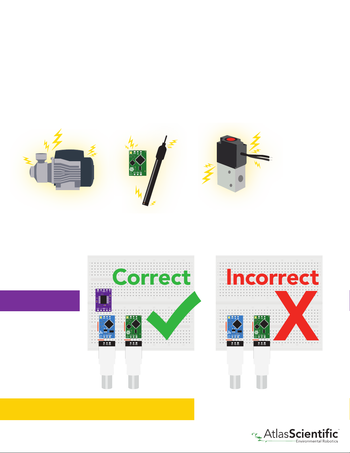
The Atlas Scientific EZO™ORP circuit is a very sensitive device. This sensitivity is what
gives the ORP circuit its accuracy. This also means that the ORP circuit is capable
of reading micro-voltages that are bleeding into the water from unnatural sources such
as pumps, solenoid valves or other probes/sensors.
When electrical noise is interfering with the ORP readings it is common to see rapidly
fluctuating readings or readings that are consistently off. To verify that electrical noise
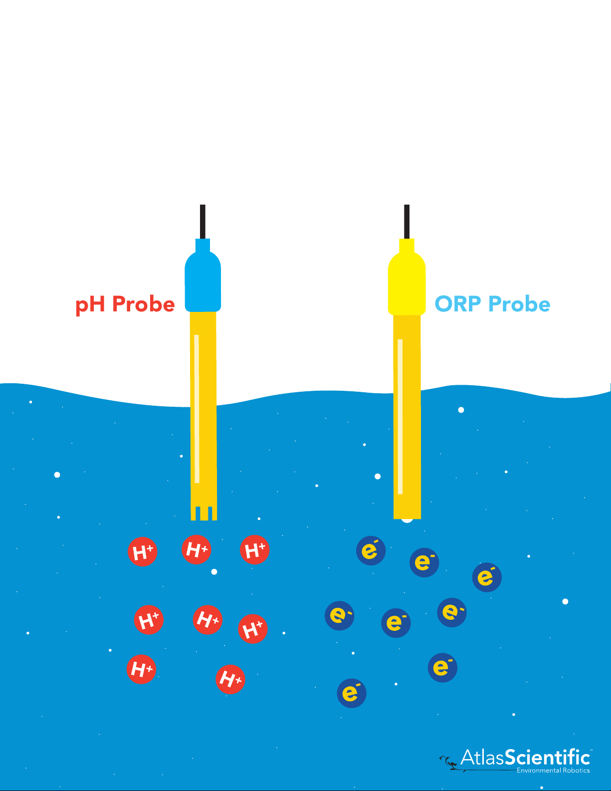
is causing inaccurate readings, place the ORP probe in a cup of water by itself. The readings
should stabilize quickly, confirming that electrical noise was the issue.
When reading ORP and Conductivity or Dissolved Oxygen together, it is
strongly recommended that the EZO™ ORP circuit is electrically isolated from
the EZO™Conductivity or Dissolved Oxygen circuit.
Without isolation, Conductivity and Dissolved Oxygen
readings will effect ORP accuracy.
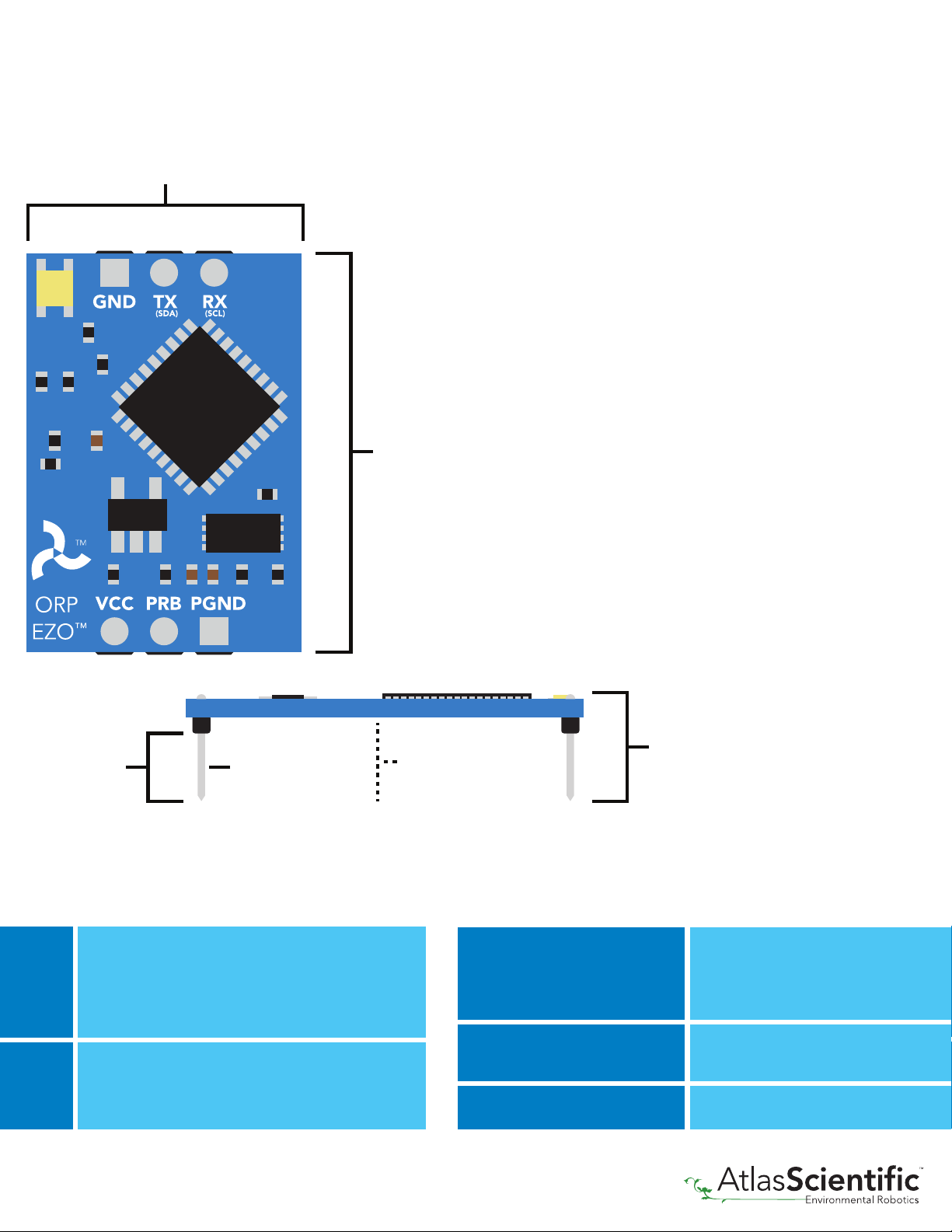
1
5
10
15
20
25
30
1
5
10
15
20
25
30
A
B
C
D
E
F
G
H
I
J
A
B
C
D
E
F
G
H
I
J
1
5
10
15
20
25
30
1
5
10
15
20
25
30
A
B
C
D
E
F
G
H
I
J
A
B
C
D
E
F
G
H
I
J
Correct
1
5
10
15
20
25
30
1
5
10
15
20
25
30
A
B
C
D
E
F
G
H
I
J
A
B
C
D
E
F
G
H
I
J
1
5
10
15
20
25
30
1
5
10
15
20
25
30
A
B
C
D
E
F
G
H
I
J
A
B
C
D
E
F
G
H
I
J
Incorrect
Basic EZO
TM
Inline Voltage Isolator
r 0.1
7Copyright © Atlas Scientific LLC

r 0.1
This schematic shows exactly how we isolate data and power using the ADM3260
and a few passive components. The ADM3260 can output isolated power up to 150 mW
and incorporates two bidirectional data channels.
This technology works by using tiny transformers to induce the voltage across an air gap.
PCB layout requires special attention for EMI/EMC and RF Control, having proper ground
planes and keeping the capacitors as close to the chip as possible are crucial for proper
performance. The two data channels have a 4.7kΩpull up resistor on both the isolated
and non-isolated lines (R1, R2, R3, and R4) The output voltage is set using a voltage
divider (R5, R6, and R,7) this produces a voltage of 3.9V regardless of your input voltage.
Isolated ground is different from non-isolated ground, these two lines should not
be connected together.
C4
10uF
C1
0.1uf
VDDP
ADM3260
HDR_BTM
ISO-VCC
ISO-VCC
ISO-VCC
ISO-VCC
ISO-VCC
R5 R7
R4
R3
1.5K
R6
1.5K
C3
C2
C6
C5
10uF
10uF
0.1uF
0.1uF
1.5K
4.7K
4.7K
VDDISO
VISO
VSEL
NCNC
SCL1
SDA1
SCL2
SDA2
VIN
GNDP
GNDISO
GNDISO
GNDISO
GNDISO
GNDP
GNDP
GNDP
PDIS
VCC
VCC
VCC
VCC
VCC
VCC
RX/SCL
TX/SDA
NC
GND
ISO-GND
ISO-GND
GND
R2 R14.7K 4.7K
R5
1M
HDR_TOP
VCC
RX/SCL
TX/SDA
EN
GND
Non-isolated
N-FET
VCC = 3.0v − 5.5v
Isolated
D
G
S
GND
VCC
R8
1M
8Copyright © Atlas Scientific LLC

Correct wiring
Incorrect wiring
Bread board
Extended leads Sloppy setup Perfboards or Protoboards *Embedded into your device
Bread board
via USB
USB
carrier board
Part #
USB-ISO
Part #
ISCCB
Part # COM-104
Carrier board
1
5
10
15
20
1
5
15
15
20
A
B
C
D
E
F
G
H
I
J
A
B
C
D
E
F
G
H
I
J
1
5
10
15
20
1
5
15
15
20
A
B
C
D
E
F
G
H
I
J
A
B
C
D
E
F
G
H
I
J
TM
Atlas
Scientific
PWR
RX
TX
1
1
5
5
10
10
15
15
20
20
25
25
30
30
35
35
40
40
45
45
50
50
55
55
60
60
A
A
B
B
C
C
D
D
E
E
F
F
G
G
H
H
I
I
J
J
RX
TX
GND
VCC
*Only after you are familar
with EZO
TM circuits operation
use Perfboards or Protoboards
NEVER
Flux residue and shorting wires make
it very hard to get accurate readings.
r 0.1
9Copyright © Atlas Scientific LLC

The Atlas Scientific EZO™ORP circuit has a flexible
calibration protocol, allowing single point calibration to
any off the shelf calibration solution.
However, If this is your first time calibrating the EZO™
ORP circuit, Atlas Scientific recommends using the 225mv
calibration solution.
Calibration theory
Simple calibration Advanced calibration
mode mode
The most important part of calibration is watching the
readings during the calibration process.
It's easiest to calibrate the device in its default state
(UART mode, with continuous readings enabled).
Switching the device to I2C mode after calibration will
not affect the stored calibration. If the device must be
calibrated in I2C mode be sure to continuously request
readings so you can see the output from the probe.
Send
152.1
197.3
210.6
295.7
306.2
315.7
315.7
315.7
315.7
315.7
315.7
Unstabilized
Stabilized
12 Copyright © Atlas Scientific LLC

If the ORP that's being read is continuously on the extremes of the scale (~ -900mV or
+900mV) calibration may have to be done more often. The exact frequency of calibration
will have to be determined by your engineering team.
Single point calibration
Remove the soaker bottle and rinse off the ORP probe. Insert the ORP probe directly into
the 225mV calibration solution bottle, and let the probe sit in the calibration solution until
the readings stabilize (small movement from one reading to the next is normal).
Send
342.0
315.2
268.7
240.1
240.1
240.1
240.1
cal,225
*OK
225.0
225.0
Unstabilized
Stabilized
Once the readings have stabilized,
issue the calibration command.
In this case "cal,225"
Calibration should be done at least once per year
10 − 60 sec
10 − 60 sec
10 − 60 sec
13 Copyright © Atlas Scientific LLC

Default state
9,600Baud
1,000 ms
Green
Standby
Cyan
Taking reading Transmitting
continuous
1 reading per second
on
Readings
Speed
LED
UART mode
14 Copyright © Atlas Scientific LLC

SPI
Analog
RS-485
Mod Bus
4–20mA
Available data protocols
Unavailable data protocols
Default
r 0.1
15 Copyright © Atlas Scientific LLC

UART mode
Settings that are retained if power is cut
Calibration
Change I2C address
Hardware switch to UART mode
LED control
Protocol lock
Software switch to UART mode
Find
Sleep mode
Settings that are NOT retained if power is cut
Settings that are retained if power is cut
Baud rate
Calibration
Continuous mode
Device name
Enable/disable response codes
Hardware switch to I2C mode
LED control
Protocol lock
Software switch to I2C mode
Find
Sleep mode
Settings that are NOT retained if power is cut
r 0.1

UART mode
Data format
Vcc
RX
Data in
Data out
TX
3.3V – 5.5V
Baud
8 data bits
1 stop bit
no parity
no flow control
300
1,200
2,400
9,600
19,200
38,400
57,600
115,200
default
0V0V
VCC
CPU
TX RX
RX TX
TX RX
Green
UART standby
Cyan
Taking reading
Purple
Changing
baud rate
Red
Command
not understood
White
Find
Data type floating point
Decimal places 1
Smallest string 2 characters
Largest string 40 characters
Reading ORP
Units mV
Encoding ASCII
Format string
Terminator carriage return
17 Copyright © Atlas Scientific LLC

Receiving data from device
2 parts
Terminator
Carriage return <cr>
Hex:
Dec:
ASCII:
32
50
2 .0 69
30
48
39
57
2E 36
46 54
0D
13
CPU
TX
RX
Blue
I2C standby
Green
Taking reading
Purple
Changing
I2C address
Red
Command
not understood
White
Find
SDA
(TX) (RX)
SCL SDA
(TX) (RX)
SCL SDA
(TX) (RX)
SCL SDA
(TX) (RX)
SCL SDA
(TX) (RX)
SCL
209.6 <cr>
9,600 baud
(default)
Receiver
Advanced
ASCII data string
Command
Sender
<cr>
r 0.1
18 Copyright © Atlas Scientific LLC

2 parts
Terminator
Carriage return <cr>
Sending commands to device
CPU
TX
RX
Short
Short
Sender
Sleep <cr>
Command (not case sensitive)
ASCII data string
Receiver
Hex:
Dec:
ASCII:
53
83
S l e e p
6C
108 101 101 112
65 65 70 0D
13
Advanced
<cr>
r 0.1
19 Copyright © Atlas Scientific LLC

CPU
TX RX
RX TX
TX RX
Green
UART standby
Cyan
Taking reading
Purple
Changing
baud rate
Red
Command
not understood
White
Find
LED color definition
r 0.1
LED ON
+2.2 mA
+0.6 mA
5V
3.3V
20 Copyright © Atlas Scientific LLC
Table of contents