DFI CMS101 User manual

CMS101/CMS103
Thin Mini-ITX
User’s Manual
© April 11, 2023 DFI Inc.

2
User's Manual | CMS101/CMS103
Copyright
This publication contains information that is protected by copyright. No part of it may be repro-
duced in any form or by any means or used to make any transformation/adaptation without the
prior written permission from the copyright holders.
This publication is provided for informational purposes only. The manufacturer makes no
representations or warranties with respect to the contents or use of this manual and specifi-
cally disclaims any express or implied warranties of merchantability or fitness for any particular
purpose. The user will assume the entire risk of the use or the results of the use of this docu-
ment. Further, the manufacturer reserves the right to revise this publication and make changes
to its contents at any time, without obligation to notify any person or entity of such revisions or
changes.
Changes after the publication’s first release will be based on the product’s revision. The website
will always provide the most updated information.
© 2023. All Rights Reserved.
Trademarks
Product names or trademarks appearing in this manual are for identification purpose only and
are the properties of the respective owners.
FCC and DOC Statement on Class A
This equipment has been tested and found to comply with the limits for a Class A digital
device, pursuant to Part 15 of the FCC rules. These limits are designed to provide reason-
able protection against harmful interference when the equipment is operated in a residential
installation. This equipment generates, uses and can radiate radio frequency energy and, if not
installed and used in accordance with the instruction manual, may cause harmful interference
to radio communications. However, there is no guarantee that interference will not occur in a
particular installation. If this equipment does cause harmful interference to radio or television
reception, which can be determined by turning the equipment off and on, the user is encour-
aged to try to correct the interference by one or more of the following measures:
• Reorient or relocate the receiving antenna.
• Increase the separation between the equipment and the receiver.
• Connect the equipment into an outlet on a circuit different from that to which the
receiver is connected.
• Consult the dealer or an experienced radio TV technician for help.
Notice:
1. The changes or modifications not expressly approved by the party responsible for com-
pliance could void the user’s authority to operate the equipment.
2. Shielded interface cables must be used in order to comply with the emission limits.

3
User's Manual | CMS101/CMS103
Table of Contents
Chapter 1 - Introduction................................................................................................................6
Specifications.........................................................................................................................6
Dimensions.............................................................................................................................8
Block Diagram ........................................................................................................................8
Chapter 2 - Hardware Installations..............................................................................................9
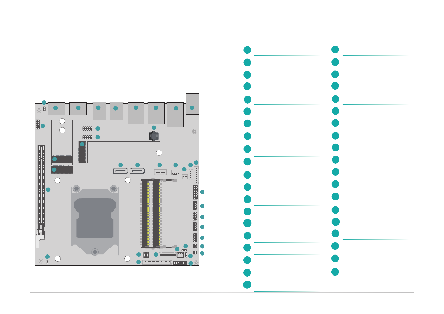
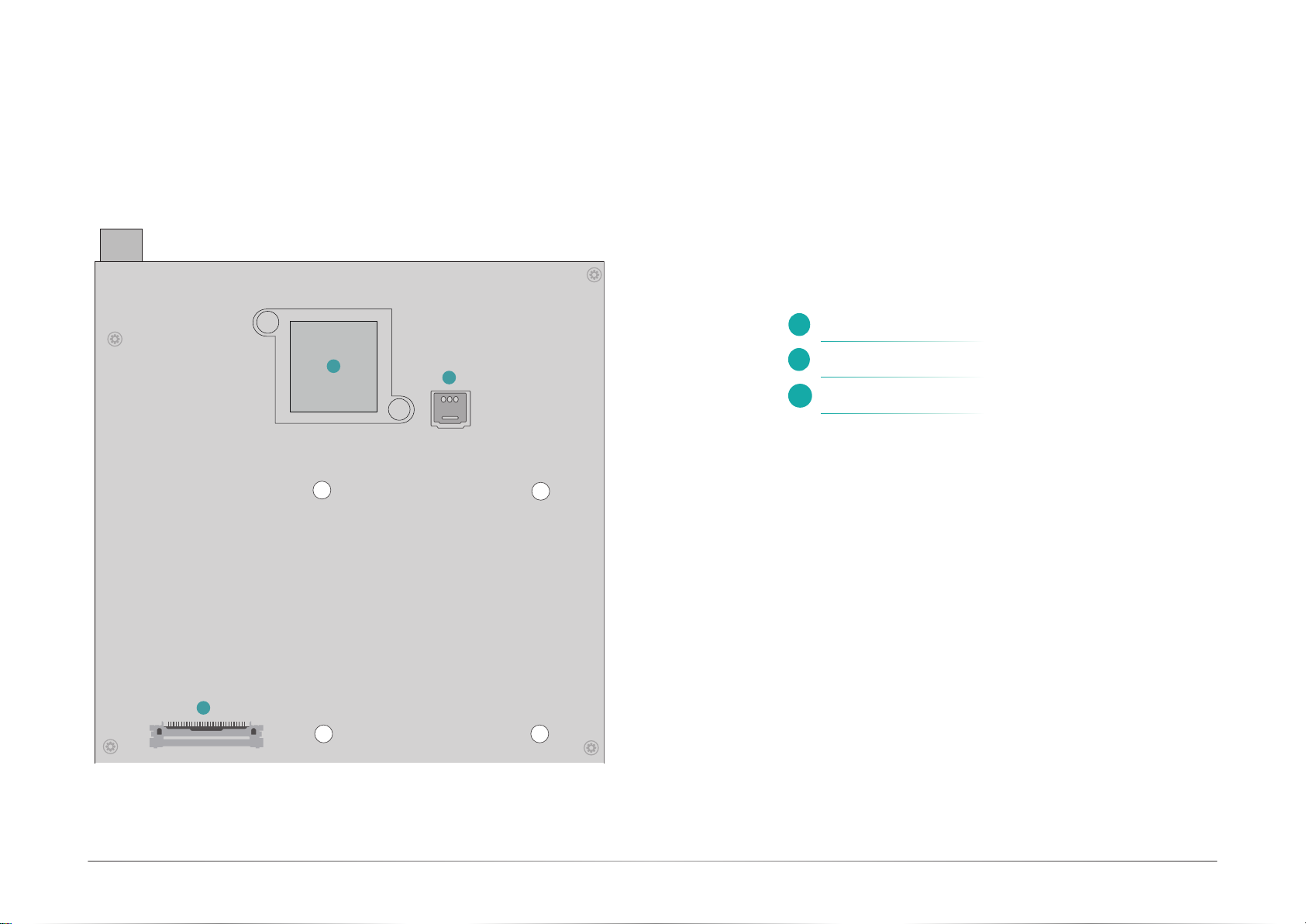
Overview..................................................................................................................................9
Top View...........................................................................................................................9
Bottom View...................................................................................................................10
Installing the heat sink.........................................................................................................11
Installing the Heat Sink.................................................................................................11
Jumper Settings...................................................................................................................12
Clear CMOS (JP1) .........................................................................................................12
Power Selection COM1 (JP2).......................................................................................12
Power Selection COM2 (JP3).......................................................................................13
LCD/Inverter Power Select (DPJP602) ........................................................................13
Backlight Voltage Select (DPJP601)............................................................................14
Panel Power Select (DPJP603)....................................................................................14
Pin Assignment....................................................................................................................15
Front Panel.....................................................................................................................15
COM 1/2 Headers: RS232/422/485 (J17, J18)..........................................................15
COM 3/4 Headers: RS232 (J15, J16)..........................................................................15
LVDS Power (DPJ601)...................................................................................................16
LPC (J14).......................................................................................................................16
Front Audio (AUJ2)........................................................................................................17
USB 2.0 5-6/7-8 Headers (UBJ7, UBJ8) ......................................................................17
Chassis Intrusion (SOJ1)..............................................................................................18
CPU Fan (J10)................................................................................................................18
SATA0 (R2)/ SATA1 (R3)...............................................................................................19
SATA Power (CN1) ........................................................................................................19
Battery (J5) ....................................................................................................................20
Digital I/O (J13).............................................................................................................20
Digital I/O Power (J12) .................................................................................................21
LVDS LCD Panel (DPCN601).........................................................................................22
eDP (CN23) *Optional...................................................................................................23
Expansion Slots....................................................................................................................24
Installing the M.2 Module.............................................................................................24
Installing the SO-DIMM Module ...................................................................................25
Chapter 3 - BIOS Settings...........................................................................................................26
Overview ...............................................................................................................................26
Updating the BIOS................................................................................................................26
Main.......................................................................................................................................27
Advanced .............................................................................................................................27
RC ACPI Settings...........................................................................................................28
CPU Configuration.........................................................................................................28
Power & Performance...................................................................................................29
PCH-FW Configuration..................................................................................................29
Trusted Computing........................................................................................................30
PTN3460 Configuration ................................................................................................31
NCT6126D Super IO Configuration..............................................................................31
NCT6126D HW Monitor ................................................................................................32
NCT6126D HW Monitor ►Smart FAN Function .................................................32
Serial Port Console Redirection ...................................................................................33
Serial Port Console Redirection ►Console Redirection Settings........................33
USB Configuration ........................................................................................................34
Network Stack Configuration........................................................................................34
CSM Configuration........................................................................................................35
USB Power Control........................................................................................................35
Chipset..................................................................................................................................36
Graphics Configuration .................................................................................................36
PEG Port Configuration.................................................................................................37
PCH-IO Configuration....................................................................................................37
PCH-IO Configuration►PCI Express Configuration.............................................38
PCH-IO Configuration►SATA And RST Configuration.........................................39
PCH-IO Configuration►HD Audio Configuration.................................................39
Security .................................................................................................................................40
Secure Boot....................................................................................................................40
Boot.......................................................................................................................................41
Save & Exit............................................................................................................................41

4
User's Manual | CMS101/CMS103
About this Manual
This manual can be retrieved from the website.
The manual is subject to change and update without notice, and may be based on editions that
do not resemble your actual products. Please visit our website or contact our sales representa-
tives for the latest editions.
Warranty
1. Warranty does not cover damages or failures that arises from misuse of the product,
inability to use the product, unauthorized replacement or alteration of components and
product specifications.
2. The warranty is void if the product has been subjected to physical abuse, improper
installation, modification, accidents or unauthorized repair of the product.
3. Unless otherwise instructed in this user’s manual, the user may not, under any circum-
stances, attempt to perform service, adjustments or repairs on the product, whether
in or out of warranty. It must be returned to the purchase point, factory or authorized
service agency for all such work.
4. We will not be liable for any indirect, special, incidental or consequential damages to
the product that has been modified or altered.
About this Package
The package contains the following items. If any of these items are missing or damaged,
please contact your dealer or sales representative for assistance.
• 1 CMS101/CMS103 motherboard
• 1 Serial ATA data & power cable w/lock (Length: 300mm)
• 1 COM port cable (Length: 250mm, 1 x COM port)
Note: The items are subject to change in the developing stage.Note: The items are subject to change in the developing stage.
The product and accessories in the package may not come similar to the information listed
above. This may differ in accordance with the sales region or models in which it was sold. For
more information about the standard package in your region, please contact your dealer or
sales representative.

5
User's Manual | CMS101/CMS103
Static Electricity Precautions
It is quite easy to inadvertently damage your PC, system board, components or devices even
before installing them in your system unit. Static electrical discharge can damage computer
components without causing any signs of physical damage. You must take extra care in han-
dling them to ensure against electrostatic build-up.
1. To prevent electrostatic build-up, leave the system board in its anti-static bag until you
are ready to install it.
2. Wear an antistatic wrist strap.
3. Do all preparation work on a static-free surface.
4. Hold the device only by its edges. Be careful not to touch any of the components, con-
tacts or connections.
5. Avoid touching the pins or contacts on all modules and connectors. Hold modules or
connectors by their ends.
Safety Precautions
• Use the correct DC / AC input voltage range.
• Unplug the power cord before removing the system chassis cover for installation or
servicing. After installation or servicing, cover the system chassis before plugging in
the power cord.
• There is danger of explosion if battery incorrectly replaced.
• Replace only with the same or equivalent specifications of batteries recommend by
the manufacturer.
• Dispose of used batteries according to local ordinance.
• Keep this system away from humid environments.
• Make sure the system is placed or mounted correctly and stably to prevent the chance
of dropping or falling may cause damage.
• The openings on the system shall not be blocked and shall be kept in distance from
other objects to make sure of proper air ventilation to protect the system from over-
heating.
• Dress the cables, especially the power cord, so they will not be stepped on, in contact
with high temperature surfaces, or cause any tripping hazards.
• Do not place anything on top of the power cord. Use a power cord that has been ap-
proved for use with the system and is compliant with the voltage and current ranges
required by the system’s electrical specifications.
• If the system is to be unused or stored for a long time, disconnect it from the power
source to avoid damage by transient overvoltage.
• If one of the following occurs, consult a service personnel:
- The power cord or plug is damaged.
- Liquid has penetrated the system.
- The system has been exposed to moisture.
- The system is not working properly.
- The system is physically damaged.
• The unit uses a three-wire ground cable which is equipped with a third pin to ground
the unit and prevent electric shock. Do not defeat the purpose of this pin. If your outlet
does not support this kind of plug, contact your electrician to replace the outlet.
• Disconnect the system from the electricity outlet before cleaning. Use a damp cloth
for cleaning the surface. Do not use liquid or spray detergents for cleaning.
• Before connecting, make sure that the power supply voltage is correct. The device is
connected to a power outlet which should be grounded connection.
Important:
Electrostatic discharge (ESD) can damage your processor, disk drive and other
components. Perform the upgrade instruction procedures described at an ESD
workstation only. If such a station is not available, you can provide some ESD pro-
tection by wearing an antistatic wrist strap and attaching it to a metal part of the
system chassis. If a wrist strap is unavailable, establish and maintain contact with
the system chassis throughout any procedures requiring ESD protection.
The system may burn fingers while running.
Wait for 30 minutes to handle electronic parts after power off.

6
Chapter 1
INTRODUCTION
User's Manual | CMS101/CMS103
Chapter 1 - Introduction
X Specifications
SYSTEM Processor 10th Gen Intel®Xeon/Core™/Pentium/Celeron Processors, LGA 1200 Socket
Intel®Xeon W-1290TE Processor (Core 10; Max speed 4.5GHz; TDP 35W) (W480E only)
Intel®Xeon W-1270TE Processor (Core 8; Max speed 4.4GHz; TDP 35W) (W480E only)
Intel®Xeon W-1250TE Processor (Core 6; Max speed 3.8GHz; TDP 35W) (W480E only)
Intel®Core i9-10900E Processor (Core 10; Max speed 4.7GHz; TDP 65W)
Intel®Core i9-10900TE Processor (Core 10; Max speed 4.5GHz; TDP 35W)
Intel®Core i7-10700E Processor (Core 8; Max speed 4.5GHz; TDP 65W)
Intel®Core i7-10700TE Processor (Core 8; Max speed 4.4GHz; TDP 35W)
Intel®Core i5-10500E Processor (Core 6; Max speed 4.2GHz; TDP 65W)
Intel®Core i5-10500TE Processor (Core 6; Max speed 3.7GHz; TDP 35W)
Intel®Core i3-10100E Processor (Core 4; Max speed 3.8GHz; TDP 65W)
Intel®Core i3-10100TE Processor (Core 4; Max speed 3.6GHz; TDP 35W)
Intel®Pentium G6400E Processor (Core 2; Max speed 3.8GHz; TDP 65W)
Intel®Pentium G6400TE Processor (Core 2; Max speed 3.2GHz; TDP 35W)
Intel®Celeron G5900E Processor (Core 2; Max speed 3.2GHz; TDP 65W)
Intel®Celeron G5900TE Processor (Core 2; Max speed 3.0GHz; TDP 35W)
Chipset Intel®W480/Q470/H420 Chipset
Memory Two 260-pin SODIMM up to 64GB
Dual Channel DDR4 2933MHz
BIOS AMI SPI 256Mbit
GRAPHICS Controller Intel® UHD Graphics 630 (only Pentium G5400/Celeron G4900 support 610 )
Feature OpenGL 4.5, DirectX 12, OpenCL 2.1
HW Decode: AVC/H.264, MPEG2, VC1/WMV9, JPEG/MJPEG, HEVC/H265, VP8, VP9
HW Encode: AVC/H.264, MPEG2, JPEG, HEVC/H265, VP8, VP9
Display 2 x DP++ (Resolution up to 4096x2304 @60Hz)
1 x LVDS (Resolution up to 1920x1200 @60Hz)
1 x eDP (Resolution up to 4096x2160 @60Hz)
Triple
Displays DP++ + DP++ + LVDS/eDP
EXPANSION Interface 1 x PCIe x16 (Gen 3)
1 x M.2 2230 E Key (USB/PCIe x1)
1 x M.2 2280 M Key (W480/Q470: PCIe x4 Gen3/SATA; H420: PCIe x1 Gen3)
1 x M.2 2242/3042/3052 B Key (W480/Q470: PCIe x1 Gen3/USB 3.2 Gen2/USB 2.0/SATA; H420: PCIe x1 Gen3/USB 3.2 Gen1/USB 2.0)
AUDIO Audio Codec Realtek ALC888/887
ETHERNET Controller 1 x Intel®I225LM PCIe(10/100/1000/2.5G speeds)
1 x Intel®I219LM PHY(10/100/1000 speeds), support vPro/AMT
1 x Intel®I211AT PCIe(10/100/1000 speeds)
REAR I/O Ethernet 1 x 2.5GbE (RJ-45)
2 x GbE (RJ-45)
USB W480/Q470: 4 x USB 3.2 Gen2 (dual type-A connector)
H420: 4 x USB 3.2 Gen1 (dual type-A connector)
Display 2 x DP++

7
Chapter 1
INTRODUCTION
User's Manual | CMS101/CMS103
INTERNAL I/O
Serial 2 x RS-232/422/485 (2.0mm pitch)
2 x RS-232 (2.0mm pitch)
USB 4 x USB 2.0 (2.0mm pitch)
Display 1 x LVDS header
1 x eDP connector
Audio 1 x Front Audio (2.0mm pitch)
SATA 2 x SATA 3.0 (up to 6Gb/s)
1 x SATA Power
RAID 0/1/5/10 (w/ M.2 M/B Key + 2 SATA Conn., W480/Q470 only)
DIO 1 x 8-bit DIO
1 x DIO Power
LPC 1 x LPC
SMBus 1 x SMBus
WATCHDOG
TIMER Output &
Interval System Reset, Programmable via Software from 1 to 255 Seconds
SECURITY TPM fTPM (default)
dTPM2.0 (opt.)
POWER
Type Single 12V +/-10% DC (CMS101)
Wide Range 15~36V (CMS103)
Connector DC-in Jack
Right Angle Connector (4-pin) (available upon request)
Straight Type Connector (4-pin) (available upon request)
Consumption Idle: i9-10900E 65W: 20V@ 0.82A (16.4W)
Max: i9-10900E 65W: 20V@ 9.02A (180.4W)
RTC Battery CR2032 Coin Cell
OS SUPPORT Microsoft Windows 10 IoT Enterprise 64-bit
Linux Linux
MECHANISM Dimensions Mini-ITX Form Factor , 170mm (6.7") x 170mm (6.7")
Height PCB: 1.6mm
Top Side: 16.3mm, Bottom Side: 4.4mm
ENVIRONMENT
Temperature Operating: -5 to 65°C
Storage: -40 to 85°C
Humidity Operating: 5 to 90% RH
Storage: 5 to 90% RH
MTBF CMS103-W480IB 554,497 hrs @ 25°C; 325,039 hrs @ 45°C; 208,771 hrs @ 60°C;
Calculation model: Telcordia Issue 4
Environment: GB, GC – Ground Benign, Controlled
CERTIFICATION Certifications CE, FCC, RoHS

8
Chapter 1
INTRODUCTION
User's Manual | CMS101/CMS103
X Dimensions X Block Diagram

9
Chapter 2
HARDWARE INSTALLATION
User's Manual | CMS101/CMS103
Chapter 2 - Hardware Installations
X Overview
Top View
1
2
3
4
5
6
9
10
11
7
14
12
13
15
8
Chassis Intrusion
DP2
DP1
USB2_3/4
USB3_3/4
USB2_1/2
USB3_1/2
LAN3
LAN2
LAN1
DC-IN
Single 12V +/-10% DC (CMS101)
Wide Range 15~36V (CMS103)
Front Audio
M.2 2230 E key
M.2 2242/3042/3052 B key
USB2_7/8
USB2_5/6
M.2 2280 M key
SPI
SATA 3.0
SATA 3.0
SATA Power
CPU FAN
1
1 2
9
1
1
210
1
210
1 1 1
DDR4_1 SODIMM (Top)
DDR4_2 SODIMM (Bottom)
11
1
1
214
1
6
1
40
1
1
6
1
6
1
45
8
1
1
1
1
12
11
12
9
12
9
12
9
12
9
1
789
10
11
12
13
14
15
16
17 18 19 20
21
22
23
24
25
26
27
28
29
30
31
32
33 34
35
36
37
38 39
23456
M.2 B-Key
M.2 E-Key
M.2 M-Key
Battery
DIO Power
DIO
PCIE 1
Clear CMOS
Front Panel
COM1
COM2
COM3
COM4
Power Selection COM 1
Power Selection COM 2
Panel Power Select
LVDS Power
SYS FAN
LCD/Inverter Power Select
Backlight Voltage Select
LVDS
LPC
16
19
17
18
20
21
22
23
24
25
26
29
30
31
27
34
32
33
35
28
36
39
37
38

10
Chapter 2
HARDWARE INSTALLATION
User's Manual | CMS101/CMS103
Bottom View
41
40
42
Nano SIM slot
eDP
Intel® W480/Q470/H420 Chipset
40
41
42

11
Chapter 2
HARDWARE INSTALLATION
User's Manual | CMS101/CMS103
X Installing the heat sink
1
1 2
9
1
1
210
1
210
1 1 1
DDR4_1 SODIMM (Top)
DDR4_2 SODIMM (Bottom)
11
1
1
214
1
6
1
40
1
1
6
1
6
1
45
8
1
1
1
1
12
11
12
9
12
9
12
9
12
9
M.2 E-Key
M.2 B-Key
M.2 M-Key
Installing the Heat Sink
The CPU must be kept cool by using a heat sink, otherwise the CPU will overheat damaging
both the CPU and system board.
1. Before you install the fan / heat sink, you must apply a thermal paste onto the top of
the CPU. The thermal paste is usually supplied when you purchase the fan / heat sink
assembly. Do not spread the paste all over the surface. When you later place the heat
sink on top of the CPU, the compound will disperse evenly.
Some heat sinks come with a patch of preapplied thermal paste. Do not apply thermal
paste if the fan / heat sink already has a patch of thermal paste on its underside. Peel
the strip that covers the paste before you place the fan / heat sink on top of the CPU.
2. Place the heat sink on top of the CPU. The 4 spring screws around the heat sink, which
are used to secure the heat sink onto the system board, must match the 4 mounting
holes around the board.
3. Screw tight two of the spring screws at opposite corners into the mounting holes. And
then proceed with the other two spring screws.
Mounting holes
Mounting holes
Note:
Some components are optional and only available upon request.
Important:
Electrostatic discharge (ESD) can damage your board, processor,
disk drives, add-in boards, and other components. Perform instal-
lation procedures at an ESD workstation only. If such a station is
not available, you can provide some ESD protection by wearing
an antistatic wrist strap and attaching it to a metal part of the
system chassis. If a wrist strap is unavailable, establish and main-
tain contact with the system chassis throughout any procedures
requiring ESD protection.

12
Chapter 2
HARDWARE INSTALLATION
User's Manual | CMS101/CMS103
X Jumper Settings
Clear CMOS (JP1)
1-2 On: Normal (default)
1
1 2
9
1
1
210
1
210
1 1 1
DDR4_1 SODIMM (Top)
DDR4_2 SODIMM (Bottom)
11
1
1
214
1
6
1
40
1
1
6
1
6
1
45
8
1
1
1
1
12
11
12
9
12
9
12
9
12
9
M.2 E-Key
M.2 B-Key
M.2 M-Key
Power Selection COM1 (JP2)
6
5
21
1-3 /2-4 On:
RS232 Standard (Default)
1
1 2
9
1
1
210
1
210
1 1 1
DDR4_1 SODIMM (Top)
DDR4_2 SODIMM (Bottom)
11
1
1
214
1
6
1
40
1
1
6
1
6
1
45
8
1
1
1
1
12
11
12
9
12
9
12
9
12
9
M.2 E-Key
M.2 B-Key
M.2 M-Key
11
2-3 On: Clear CMOS
6
5
21
3-5 /4-6 On:
RS232 with Power

13
Chapter 2
HARDWARE INSTALLATION
User's Manual | CMS101/CMS103
Power Selection COM2 (JP3)
1
1 2
9
1
1
210
1
210
1 1 1
DDR4_1 SODIMM (Top)
DDR4_2 SODIMM (Bottom)
11
1
1
214
1
6
1
40
1
1
6
1
6
1
45
8
1
1
1
1
12
11
12
9
12
9
12
9
12
9
M.2 E-Key
M.2 B-Key
M.2 M-Key
LCD/Inverter Power Select (DPJP602)
1
1-2 On: +12V (Default)
1
1 2
9
1
1
210
1
210
1 1 1
DDR4_1 SODIMM (Top)
DDR4_2 SODIMM (Bottom)
11
1
1
214
1
6
1
40
1
1
6
1
6
1
45
8
1
1
1
1
12
11
12
9
12
9
12
9
12
9
M.2 E-Key
M.2 B-Key
M.2 M-Key
2-3 On: +5V
6
5
21
1-3 /2-4 On:
RS232 Standard (Default)
6
5
21
3-5 /4-6 On:
RS232 with Power
1

14
Chapter 2
HARDWARE INSTALLATION
User's Manual | CMS101/CMS103
Backlight Voltage Select (DPJP601)
1-2 On: 3V3 (Default)
1
1 2
9
1
1
210
1
210
1 1 1
DDR4_1 SODIMM (Top)
DDR4_2 SODIMM (Bottom)
11
1
1
214
1
6
1
40
1
1
6
1
6
1
45
8
1
1
1
1
12
11
12
9
12
9
12
9
12
9
M.2 E-Key
M.2 B-Key
M.2 M-Key
11
2-3 On: 5V
Panel Power Select (DPJP603)
1
1 2
9
1
1
210
1
210
1 1 1
DDR4_1 SODIMM (Top)
DDR4_2 SODIMM (Bottom)
11
1
1
214
1
6
1
40
1
1
6
1
6
1
45
8
1
1
1
1
12
11
12
9
12
9
12
9
12
9
M.2 E-Key
M.2 B-Key
M.2 M-Key
65
21
1-2 On: 12V 3-4 On: 5V
65
21
65
21
5-6 On: 3.3V (Default)

15
Chapter 2
HARDWARE INSTALLATION
User's Manual | CMS101/CMS103
X Pin Assignment
Front Panel
1
1 2
9
1
1
210
1
210
1 1 1
DDR4_1 SODIMM (Top)
DDR4_2 SODIMM (Bottom)
11
1
1
214
1
6
1
40
1
1
6
1
6
1
45
8
1
1
1
1
12
11
12
9
12
9
12
9
12
9
M.2 E-Key
M.2 B-Key
M.2 M-Key
COM 1/2 Headers: RS232/422/485 (J17, J18)
COM 3/4 Headers: RS232 (J15, J16)
1
1 2
9
1
1
210
1
210
1 1 1
DDR4_1 SODIMM (Top)
DDR4_2 SODIMM (Bottom)
11
1
1
214
1
6
1
40
1
1
6
1
6
1
45
8
1
1
1
1
12
11
12
9
12
9
12
9
12
9
M.2 E-Key
M.2 B-Key
M.2 M-Key
COM 1/2
COM 3/4
Pin RS232 RS422 Full
Duplex RS485
1DCD- TX- DATA-
2RD TX+ DATA+
3TD RX+ NC
4DTR- RX- NC
5GND GND GND
6DSR- NC NC
7RTS- NC NC
8CTS- NC NC
9RI- NC NC
Pin Assignment Pin Assignment
1NC
PWR-LED
23V3SB
HD-LED
33V3 43V3SB
5HD_LED 6SUS_LED
RESET
7GND
ATX-SW
8GND
9PM_SYSRST 10 PWR_BTN-
11 NC 12 ---

16
Chapter 2
HARDWARE INSTALLATION
User's Manual | CMS101/CMS103
LVDS Power (DPJ601)
1
1 2
9
1
1
210
1
210
1 1 1
DDR4_1 SODIMM (Top)
DDR4_2 SODIMM (Bottom)
11
1
1
214
1
6
1
40
1
1
6
1
6
1
45
8
1
1
1
1
12
11
12
9
12
9
12
9
12
9
M.2 E-Key
M.2 B-Key
M.2 M-Key
LPC (J14)
1
1 2
9
1
1
210
1
210
1 1 1
DDR4_1 SODIMM (Top)
DDR4_2 SODIMM (Bottom)
11
1
1
214
1
6
1
40
1
1
6
1
6
1
45
8
1
1
1
1
12
11
12
9
12
9
12
9
12
9
M.2 E-Key
M.2 B-Key
M.2 M-Key
Pin Assignment Pin Assignment
1CLK 2LAD1
3RST# 4LAD0
5FRAME# 63V3
7LAD3 8GND
9LAD2 10 ---
11 SERIRQ 12 GND
13 5VSB 14 5V
Pin Assignment
1GND
2GND
3Panel Inverter Brightness Voltage Control
4Panel Power
5+3.3V
6Panel Backlight On/O Control
7LCD/Inverter Power
8LCD/Inverter Power

17
Chapter 2
HARDWARE INSTALLATION
User's Manual | CMS101/CMS103
Front Audio (AUJ2)
1
1 2
9
1
1
210
1
210
1 1 1
DDR4_1 SODIMM (Top)
DDR4_2 SODIMM (Bottom)
11
1
1
214
1
6
1
40
1
1
6
1
6
1
45
8
1
1
1
1
12
11
12
9
12
9
12
9
12
9
M.2 E-Key
M.2 B-Key
M.2 M-Key
USB 2.0 5-6/7-8 Headers (UBJ7, UBJ8)
1
1 2
9
1
1
210
1
210
1 1 1
DDR4_1 SODIMM (Top)
DDR4_2 SODIMM (Bottom)
11
1
1
214
1
6
1
40
1
1
6
1
6
1
45
8
1
1
1
1
12
11
12
9
12
9
12
9
12
9
M.2 E-Key
M.2 B-Key
M.2 M-Key
Pin Assignment Pin Assignment
1Mic2-L 2GND
3Mic2-R 4NC
5Line2-R 6Mic2-JD
7GND 8---
9Line2-L 10 Line2-JD
USB 2.0 7-8
USB 2.0 5-6
Pin Assignment Pin Assignment
1PWR 2PWR
3DATA- 4DATA-
5DATA+ 6DATA+
7GND 8GND
9--- 10 NC

18
Chapter 2
HARDWARE INSTALLATION
User's Manual | CMS101/CMS103
Chassis Intrusion (SOJ1)
1
1 2
9
1
1
210
1
210
1 1 1
DDR4_1 SODIMM (Top)
DDR4_2 SODIMM (Bottom)
11
1
1
214
1
6
1
40
1
1
6
1
6
1
45
8
1
1
1
1
12
11
12
9
12
9
12
9
12
9
M.2 E-Key
M.2 B-Key
M.2 M-Key
CPU Fan (J10)
1
1 2
9
1
1
210
1
210
1 1 1
DDR4_1 SODIMM (Top)
DDR4_2 SODIMM (Bottom)
11
1
1
214
1
6
1
40
1
1
6
1
6
1
45
8
1
1
1
1
12
11
12
9
12
9
12
9
12
9
M.2 E-Key
M.2 B-Key
M.2 M-Key
Pin Assignment
1Signal
2GND
Pin Assignment
1GND
212V
3Sense
4Speed Control

19
Chapter 2
HARDWARE INSTALLATION
User's Manual | CMS101/CMS103
SATA0 (R2)/ SATA1 (R3)
1
1 2
9
1
1
210
1
210
1 1 1
DDR4_1 SODIMM (Top)
DDR4_2 SODIMM (Bottom)
11
1
1
214
1
6
1
40
1
1
6
1
6
1
45
8
1
1
1
1
12
11
12
9
12
9
12
9
12
9
M.2 E-Key
M.2 B-Key
M.2 M-Key
SATA Power (CN1)
1
1 2
9
1
1
210
1
210
1 1 1
DDR4_1 SODIMM (Top)
DDR4_2 SODIMM (Bottom)
11
1
1
214
1
6
1
40
1
1
6
1
6
1
45
8
1
1
1
1
12
11
12
9
12
9
12
9
12
9
M.2 E-Key
M.2 B-Key
M.2 M-Key
SATA0 (R2)
SATA1 (R3)
Pin Assignment
1GND
2TX+
3TX-
4GND
5RX-
6RX+
7GND
Pin Assignment
1+12V
2GND
3GND
45V

20
Chapter 2
HARDWARE INSTALLATION
User's Manual | CMS101/CMS103
Battery (J5)
1
1 2
9
1
1
210
1
210
1 1 1
DDR4_1 SODIMM (Top)
DDR4_2 SODIMM (Bottom)
11
1
1
214
1
6
1
40
1
1
6
1
6
1
45
8
1
1
1
1
12
11
12
9
12
9
12
9
12
9
M.2 E-Key
M.2 B-Key
M.2 M-Key
Digital I/O (J13)
1
1 2
9
1
1
210
1
210
1 1 1
DDR4_1 SODIMM (Top)
DDR4_2 SODIMM (Bottom)
11
1
1
214
1
6
1
40
1
1
6
1
6
1
45
8
1
1
1
1
12
11
12
9
12
9
12
9
12
9
M.2 E-Key
M.2 B-Key
M.2 M-Key
Pin Assignment
1+3.3V
2GND
Pin Assignment
1DIO0
2DIO1
3DIO2
4DIO3
5DIO4
6DIO5
7DIO6
8DIO7
Other manuals for CMS101
1
This manual suits for next models
1
Table of contents
Other DFI Motherboard manuals

DFI
DFI CMS311-W480E/Q470E User manual

DFI
DFI NB60-EL User manual

DFI
DFI AL102 User manual

DFI
DFI SB102-D User manual

DFI
DFI SD170 User manual

DFI
DFI LanParty UT NF4 SLI EXPERT Venus User manual

DFI
DFI PIC-Q170 User manual

DFI
DFI Blood-Iron P43-T34 User manual

DFI
DFI Lanparty JR P45-T2RS User manual

DFI
DFI CB64-BX User manual