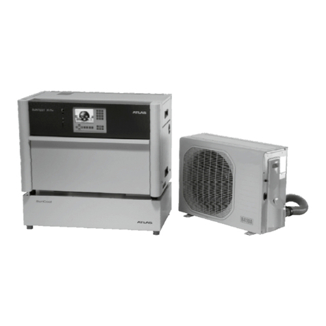
Atlas SunCool User manual

Operating instructions
Chiller SunCoolTM
OPERATION
OFF ON
THERMOSTAT
WAIT 3 MINUTES BEFORE RESTARTING
3
1
579
11
COOLER
FANSPEED
LOW HIGH
OPERATIONTHERMOSTAT
0
F
A
N
C
O
O
L
d
d
1
9
8
7
654
3
2
C
O
O
L
E
R
BEFORERESTARTING
WAITTHREEMINUTES

Operating instructions SunCoolTM
-2-
1Safety instructions .................................................................................................................................4
1.1 Explanation of symbols .......................................................................................................................6
1.2 General safety instructions ..................................................................................................................7
2Scope of delivery and equipment .........................................................................................................8
2.1 Scope of delivery ................................................................................................................................8
2.2 Optional equipment .............................................................................................................................8
2.3 ID numbers for equipment / accessories ...............................................................................................9
3Descriptionofunitandfunctions .........................................................................................................10
3.1 Description of the unit .......................................................................................................................10
3.2 Description of the functions ................................................................................................................ 11
4Start-up ...............................................................................................................................................12
4.1 Checking the trough plug ...................................................................................................................12
4.2 Visual inspection ..............................................................................................................................12
4.3 Installation of the SunCoolTM ..............................................................................................................13
4.4 Connecting SUNTEST to SunCoolTM ...................................................................................................13
4.5 Connection line and dummy plug........................................................................................................14
4.6 Connection to an aspiration system....................................................................................................14
4.7 Insulation pads for SUNTEST.............................................................................................................15
4.8 Establishing the mains connection .....................................................................................................15
5Operationandshut-down ....................................................................................................................16
5.1 Function of controls ..........................................................................................................................16
5.2 Settings ...........................................................................................................................................17
6Performanceratings ...........................................................................................................................18
6.1 Performance at normal operation ........................................................................................................18
6.2 Test chamber and black standard temperature in SUNTEST CPS+ with SunCoolTM 115V / 60Hz ..............18
6.3 Test chamber and black standard temperature in SUNTEST CPS+ with SunCoolTM 230V / 50Hz ..............19
6.4 Test chamber and black standard temperature in SUNTEST XLS+
with SunCoolTM 115V / 60 Hz und 230V / 50Hz ....................................................................................19
7Cleaning .............................................................................................................................................20
7.1 Cleaning the housing.........................................................................................................................20
7.2 Cleaning the grid and the air filter .......................................................................................................20
7.3 Replacement of the air filter ...............................................................................................................21
8Maintenance .......................................................................................................................................22
8.1 Checks and service...........................................................................................................................22
8.2 Repairs ............................................................................................................................................22
9Troubleshooting ..................................................................................................................................23
10 Specifications .....................................................................................................................................24
10.1 SunCoolTM units for SUNTEST CPS / CPS+ weathering units ...............................................................24
10.2 SunCoolTM units for SUNTEST XLS / XLS+ weathering units .................................................................25
Contents Page

-3-
Operating instructions SunCoolTM
Table 1 ID numbers for equipment / accessories ................................................................................................9
Table 2 Performance at normal operation ........................................................................................................18
Diag. 1 Test chamber and black standard temperature in SUNTEST CPS+ with SunCoolTM 115V / 60Hz ..............18
Diag. 2 Test chamber and black standard temperature in SUNTEST CPS+ with SunCoolTM 230V / 50Hz ..............19
Diag. 3 Test chamber and black standard temperature in SUNTEST XLS+
with SunCoolTM 115V / 60 Hz und230V / 50Hz .....................................................................................19
Fig. 1 Scope of delivery .................................................................................................................................8
Fig. 2 Optional equipment .............................................................................................................................8
Fig. 3 Description of the unit........................................................................................................................10
Fig. 4 Description of the unit........................................................................................................................ 11
Fig. 5 Checking the trough plug ...................................................................................................................12
Fig. 6 Visual inspection ..............................................................................................................................12
Fig. 7 Installation of the SunCoolTM ..............................................................................................................13
Fig. 8 Connectiong SUNTEST to SunCoolTM .................................................................................................13
Fig. 9 Connection line and dummy plug ........................................................................................................14
Fig. 10 Insulation pads for SUNTEST .............................................................................................................15
Fig. 11 Establishing the mains connection .....................................................................................................15
Fig. 12 Function of controls...........................................................................................................................16
Fig. 13 Operation with the SUNTEST weathering unit and shut-down ................................................................17
Fig. 14 Replacement of the air filter................................................................................................................21
Figures Page
Tables and diagrams Page

Operating instructions SunCoolTM
-4-
Dear user,
Please note that only persons with suitable qualification are allowed to work with this unit:
•TheSunCoolTM mustonlybeoperatedandcleanedbytrainedandauthorizedlaboratorypersonnel,
•Maintenanceworktothe unit must only becarriedoutby adequatelytrainedpersonnel of the operator or
ofthemanufacturer.
•Theseoperatinginstructionsdescribethe following four versions of thechillerSunCoolTM:
-SunCoolTM 115V; 60Hz for SUNTEST CPS / CPS+
-SunCoolTM 230V; 50Hz for SUNTEST CPS / CPS+
-SunCoolTM 115V; 60Hz for SUNTEST XLS / XLS+
-SunCoolTM 230V; 50Hz for SUNTEST XLS / XLS+
•Before using the SunCoolTM
for the first time, please read these operating instructions carefully. You will then be able
to fully exploit all the features of the unit and to protect yourself and others from injuries.
•For safety reasons, please contact your supplier if problems occur that are not adequately described in these
operating instructions.
1Safety instructions
ATLASMaterialTestingTechnologyGmbH
Vogelsbergstraße22
D-63589Linsengericht
Germany
Phone++49/6051/707-140
Fax ++ 49 / 6051 / 707-149

-5-
Operating instructions SunCoolTM
Dear operator,
•This unit has been manufactured in accordance with the latest technological developments and is operationally safe.
However, the unit may present potential hazards, particularly if it is operated by inadequately trained personnel or if it
is not used correctly according to the intended purpose.
•For any operation of this unit, the operator must prepare written instructions in a reasonable form and in the language
of the operating personnel based on these safety instructions (Germany: Accident Prevention Regulations, UVV VBG
1 § 7, 2).
•Use these operating instructions to familiarize the operating and cleaning personnel with the functions, operation, and
maintenance of the unit.
•The contents of the operating instructions are subject to change without further notice.
•Concerning translations into foreign languages, the German version of these operating instructions is binding.
•For safety reasons, unauthorized modifications or reconditioning of the unit are prohibited.
•For safety reasons, please contact your supplier if problems occur that are not adequately described in these opera-
ting instructions.
Keeptheseoperatinginstructionsclosetotheunitsothatsafetyinstructionsandimportantinformationare
always accessible.
1Safety instructions
Trademarks:
SunCoolTM is a registered trademark of ATLAS Material Testing Technology BV.
All other trademarks mentioned in the operating instructions are the exclusive property of the respective manufacturers.
Copyright©
1999, ATLAS MTT BV • D-63558 Gelnhausen • Germany
Edition:
December1999

Operating instructions SunCoolTM
-6-
1Safety instructions
1.1 Explanation of symbols
The following safety symbols are used to draw your
attentiontosafety-criticaloperatingerrors.
Symbols used in the operating instructions:
WARNING!
is used if non-observance may cause serious or even lethal
injuries.
CAUTION!
is used if non-observance may cause medium to minor inju-
ries or damage.
NOTE!
is used for hints and useful information.
ENVIRONMENT!
is used for hints on safe disposal.
CEconformitysymbol
Symbols on the unit:
CEconformitysymbol

-7-
Operating instructions SunCoolTM
1.2 General safety instructions
Mainsconnection:
The SunCoolTM units have been designed for varous mains
voltages.
•230 V ± 10%, 50 Hz
•115 V ± 10%, 60 Hz
The mains voltage used for the connection must comply
with the ratings on the nameplate of the unit.
Disposal:
•Please discard the packaging materials in accordan-
ce with existing disposal directives.
•Discarded units contain reusable materials. Therefore,
before discarding units, ask your local magistrate or
community office about the possibilities of recycling.
Specialwaste:
Please note that the coolant in SunCoolTM units must be
disposed of by a special refrigeration company.
1Safety instructions
Correctusage:
•The SunCoolTM is used to supply SUNTEST weathering
units with constantly conditioned cooling air.
•The SunCoolTM is suited for permanent operation.
•The SunCoolTM can be operated in enclosed spaces,
despite the hot exhaust air that is generated there.
The hot exhaust air increases the room temperature.
•To ensure constant room temperature, the unit may be
connectedto anaspieation system.The minimum aspi-
ration capacity of that system must not be lower than
520 m3/h.
Incorrectusage:
•The SunCoolTM must not be used for drying, cooling or
heating items or food.
•The SunCoolTM isnot suited for use in areas with explo-
sion hazard.
•Make sure the ventilations grids are not blocked.
Theunitis inaccordancewiththe requirementsof
the following standard:
•DIN EN 61010

Operating instructions SunCoolTM
-8-
2Scope of delivery and equipment
Figure2
Figure12.1 Scope of delivery
The SunCoolTM units are available in four different versions.
The supply voltages of the chillers are classified in accor-
dance with the weathering units SUNTEST CPS /CPS+
and SUNTEST XLS / XLS+.
After unpacking the unit, check to see if the supply voltage
complies with the voltage on the nameplate of the unit.
For SUNTEST CPS / CPS+:
SunCoolTM with 115V / 60Hz supply voltage
SunCoolTM with 230V / 50Hz supply voltage
For SUNTEST XLS / XLS+:
SunCoolTM with 115V / 60Hz supply voltage
SunCoolTM with 230V / 50Hz supply voltage
Connection line:
The connection line is used to control the SunCoolTM by
using the program control of the SUNTEST CPS+ or SUN-
TEST XLS+.
Dummy plug:
The SunCoolTM is equipped with a dummy plug to be used
if the SunCoolTM is operated with the SUNTEST CPS or
SUNTEST XLS (without program control).
PVCadhesivetape:
PVC adhesive tape is used to attach the connector to the
connection socket and pipe bend.
2.2 Optional equipment
The optional connection set connects the SunCoolTM to
the SUNTEST weathering unit.
For each SUNTEST version, a unit-specific connection set
is available that may be routed to the right or downward:
•A, connection set SUNTEST CPS / CPS+
•B, connection set SUNTEST XLS / XLS+
Scopeofdeliveryfortheconnectionset:
1connection socket SUNTEST unit, 1.
1pipe bend 90°, 2.
1connector, 30 cm, 3.
Insulationpadsfor SUNTEST weatheringunits:
Insulation pads 4prevent the formation of condensate on
the housing of the SUNTEST unit.
OPERATION OFF ON
THERMOSTAT
WAIT 3 MINUTES BEFORE RESTARTING
3
1
57911
COOLER FANSPEED
LOW HIGH
OPERATIONTHERMOSTAT
0
C
O
O
L
d
d
19
8
76543
2
C O
O
L
E
R
BEFORERESTARTING
WAITTHREEMINUTES
F
A
N
SunCoolTM 230 V, 50Hz
SunCoolTM 115 V, 60Hz
Connection line
Dummy plug
PVC adhesive tape
1
A B
2
3
4
4
Connection socket SunCoolTM
1Connection socket
2Pipe bend
3Connector
4Insulation pads

-9-
Operating instructions SunCoolTM
2Scope of delivery and equipment
Table 12.3 IDs for equipment/accessories
Pos. Accessories Description ID no.:
1Accessories for SunCool 115 V / 60 Hz in connection with SUNTEST CPS / CPS+
1.1 Connection set
for SUNTEST CPS / CPS+ Connecting elements between the cooler
SunCool and SUNTEST CPS / CPS+. 5607 8132
1.2 Baffle For connecting the SunCool to an on-site
exhaust air system. ---
1.3 Insulation pads To prevent the formation of condensate on the
surface of the SUNTEST unit. 5607 7904
2Accessories for SunCool 230 V / 50 Hz in connection with SUNTEST CPS / CPS+
2.1 Connection set
for SUNTEST CPS / CPS+ Connecting elements between the cooler
SunCool and SUNTEST CPS / CPS+. 5607 8132
2.2 Baffle For connecting the SunCool to an on-site
exhaust air system. ---
2.3 Insulation pads To prevent the formation of condensate on the
surface of the SUNTEST unit. 5607 7904
3Accessories for SunCool 115 V / 60 Hz in connection with SUNTEST XLS / XLS+
3.1 Connection set
for SUNTEST XLS / XLS+ Connecting elements between the cooler
SunCool and SUNTEST XLS / XLS+. 5607 8133
3.2 Baffle For connecting the SunCool to an on-site
exhaust air system. 5607 7986
3.3 Insulation pads To prevent the formation of condensate on the
surface of the SUNTEST unit. 5607 7983
4Accessories for SunCool 230 V / 50 Hz in connection with SUNTEST XLS / XLS+
4.1 Connection set
for SUNTEST XLS / XLS+ Connecting elements between the cooler
SunCool and SUNTEST XLS / XLS+ 5607 8133
4.2 Baffle For connecting the SunCool to an on-site
exhaust air system. 5607 7985
4.3 Insulation pads To prevent the formation of condensate on the
surface of the SUNTEST unit. 5607 7983
5Installation accessories
5.1 Table trolley for SUNTEST For installing the SUNTEST CPS / CPS+ and
SUNTEST XLS / XLS+ weathering units 5607 7857
5.2 Shelf For installing the SUNTEST CPS / CPS+
weathering units 5607 7856

Operating instructions SunCoolTM
- 10 -
3Description of unit and functions
Figure3
1Control panel
2Air inlet opening
3Air outlet opening
4Ventilation slots
5Program control
6Connection sets
(Connection set CPS / CPS+ shown)
7Connection line
8Dummy plug
4
1
OPERATION OFF ON
THERMOSTAT
WAIT3MINUTESBEFORERESTARTING
3
1
579
11
COOLER
FANSPEED
LOW HIGH
2
3
5
6
7
8
3.1 Description of the unit
Frontsideoftheunit:
•Control panel 1with switches for setting fan speed
and cooling performance.
•Air inlet opening 2with grid and air filter.
•Air outlet opening 3.
Upperandrightsideoftheunit:
•Ventilation slots 4for ventilation of the unit.
•Powet supply line 5.
Rearsideoftheunit:
•Air outlet opening for hot exhaust air.
Connectionset(Example:SUNTESTCPS/CPS+):
•The connection set6is used to connect the SunCoolTM
to the SUNTEST weathering unit. For each SUNTEST
version, a unit-specific connection set is available (see
section 2.2, "Optional equipment").
Connection line and dummy plug:
•If the SunCoolTM is operated in connection with a SUN-
TEST CPS+ or XLS+, the chiller is controlled by the
program control of the weathering unit. For this purpo-
se, the two units are interconnected with the connec-
tion line 7.
•If the SunCoolTM is operated in connection with a SUN-
TEST CPS or XLS (without program control), a dummy
plug 8is used for the SunCoolTM instead of the con-
nection line.

- 11 -
Operating instructions SunCoolTM
Figure4
1Room air
2Heated exhaust air
3Cooled air
2
OPERATION OFF ON
THERMOSTAT
WAIT 3 MINUTES BEFORE RESTARTING
3
1
579
11
COOLER
FANSPEED
LOW HIGH
1
3
3.2 Description of the functions
The room air 1is aspired through an air filter by a radial
fan at the air inlet opening. The air then flows through a
heat exchanger and is cooled. The condensate formed du-
ring this process is collected in a trough at the bottom of
the unit and evaporates during the operation of the unit.
The cooled air 3is fed to the SUNTEST weathering unit
via the connection set.
The heated exhaust air 2generated during the cooling
process is blown out on the rear side of the SunCoolTM.
NOTE:
Continuous operation of the SunCoolTM without on-site ex-
haust air system will result in a constant change of the
room atmosphere.
3Description of unit and functions

Operating instructions SunCoolTM
- 12 -
Figure5
4Start-up
1Plug at the rear side of the unit.
2Plug at the bottom of the unit.
1
2
4.1 Checking the trough plug
The condensate forming during the operation of the unit is
collected in a trough at the bottom of the unit. The con-
densate evaporates during normal operation of the unit.
A plug at the trough prevents the water from escaping.
Before the initial operation of the unit, make sure that the
plug is installed.
VersionA:
The plug 1is located at the rear side of the unit.
Version B:
The plug 2is located at the bottom of the unit.
Figure6
OPERATION OFF ON
THERMOSTAT
WAIT3 MINUTESBEFORE RESTARTING
3
1
579
11
COOLER
FAN SPEED
LOW HIGH
4.2 Visual inspection
Prior to the installation of the unit, check to see if the refri-
gerant circulation system is working properly. There must
be no coolant leakages.
WARNING - Health hazard:
Contactwithrefrigerantmaycauseinjuriesto
theskinandtothemucousmembranes.
Avoidcontactwithrefrigerant.Wearprotecti-
veglovesanddiscardescapedrefrigerantas
special waste.
•After contact with refrigerant, rinse refrigerant off with
plenty of running water.
•After a refrigerant leakage, do not operate the unit and
contact Technical Service.

- 13 -
Operating instructions SunCoolTM
4Start-up
Figure84.4 Connecting SUNTEST to SunCoolTM
Install the SunCoolTM either below or to the right of the
SUNTEST unit at a distance of approximately 60 cm.
A preferably short distance between the two units will re-
duce the loss of cooling performance.
The connecting hose between the two units should not be
longer than 100 centimeters.
NOTE:
As the two control panels are facing each other, the units
must be accessible from two sides.
Installationoftheconnectionset:
1. Remove the filter mat1from the air inlet opening of the
SUNTEST.
2. Attach the SUNTEST connection socket 3to the air
inlet opening of the SUNTEST 2at the rear of the unit.
To do so, insert the upper sheet metal tag into the filter
opening, then slide the connection socket down until it
is engaged.
3. Attach the pipe bend 4to the connection socket.
4. Insert the SunCoolTM connection socket 6into the air
outlet opening of the SunCoolTM 7.
To do so, insert the upper sheet metal tag, then the
lower sheet metal tag into the filter opening and slide
the connection socket down until it is engaged.
4. Slide the connector 5onto the connection socket and
secure it using PVC adhesive tape.
„
2
3
6
5
7
1
4
SUNTEST CPS/CPS+ SUNTEST XLS/XLS+
1Filter mat
2Air inlet opening for SUNTEST
3Connection socket for SUNTEST
4Pipe bend
5Connector
6Connection socket for SunCoolTM
7Air outlet opening for SunCoolTM
Figure7
10 cm
10 cm30 cm
4.3 Installation of the SunCoolTM
CAUTION - Overheating of the unit:
Blockedairinlet andoutletopeningsmay causeunit
overheating. In this case, the unit will be switched
offorthecooling performance willbereducedc.
•Always observe the safety distances around the unit as
shown in Fig. 7.
NOTE - Horizontal positioning of the unit:
If the unit is not installed horizontally or at elevated room
temperatures, the condensate in the trough may overflow.
•Always install the SunCoolTM horizontally.
•Check condensate level. If required, empty trough by
slightly tilting the SunCoolTM.

Operating instructions SunCoolTM
- 14 -
Figure9
4Start-up
1Connection line plug
2Connection socket on the SunCoolTM control panel
3Connection socket of the SUNTEST CPS+ / XLS+
4Dummy plug
„
OPERATIONTHERMOSTAT
0
F
A
N
C
O
O
L
1
9
8
7
654
3
2
C
O
O
L
E
R
BEFORE RESTARTING
WAIT THREE MINUTES
OPERATION OFF ON
THERMOSTAT
WAIT 3 MINUTES BEFORE RESTARTING
3
1
579
11
COOLER
FAN SPEED
LOW HIGH
SunCool 115 V / 60Hz
SunCool 230 V / 50Hz
1
2
4
3
SUNTEST CPS / CPS+ SUNTEST XLS / XLS+
4.5 Connection line and dummy plug
Connection line:
The connection line is used to control the SunCoolTM by
using the program control of the weathering unit SUNTEST
CPS+ or SUNTEST XLS+.
Dummy plug:
If the SunCoolTM is operated in connection with a SUN-
TEST CPS or SUNTEST XLS (without program control),
the connection socket of the SunCoolTM is capped with a
dummy plug.
5.4.1 Connecting the connection line:
NOTE:
When operating the SunCoolTM with a SUNTEST CPS+ or
SUNTEST XLS +, the connection line 1must be connec-
ted since otherwise the SunCoolTM will not be turned off
after program completion or if a failure occurs.
1. Plug the connector of the connection line 1into the
receptacle 2at the control panel of the SunCoolTM.
2. Plug the other connector of the connection line into the
receptacle of the SUNTEST CPS+ / XLS+ 3at the
rear of the unit.
3. In the main menu of the SUNTEST unit's program con-
trol, press button "4" and select "cooling unit".
5.4.2 Installingthedummyplug:
NOTE:
The SunCoolTM can not be operated without the dummy
plug 4.
1. Insert the dummy plug 4into the connection socket
on the control panel of the SunCoolTM 2.
4.6 Connection to an aspiration system
For removing the exhaust air, the chiller can be connected to
an on-site, corrosion-resistant aspiration system.
A baffle is available for the connection to the on-site aspirati-
on system (see chapter 5, "Accessories").
CAUTION - Freeze-up of the SunCoolTM:
The aspiration system must have a minimum perfor-
mance via the volume flow of the SunCoolTM (see
"Specifications"). If the performance is lower than
specified,theSunCoolTM may freeze up.
•Check the performance of the aspiration system.
•Do not connect the unit to an aspiration system whose
performance is lower than specified.

- 15 -
Operating instructions SunCoolTM
4Start-up
Figure 104.7 Insulation pads for SUNTEST
Insulation pads prevent the formation of condensate on the
housing of the SUNTEST unit.
NOTE-Adhesion:
Since the insulation pads are highly adhesive and difficult
to remove after attachment, it is recommended to mark
the positions of the pads before attaching them to the
surface.
Procedure:
1. Clean the housing surface with a conventional cleaning
agent. The contact surfaces must be dry and free from
grease and dust.
2. Mark the position, remove the backing tape, and at-
tach the insulation pads.
SUNTEST CPS / CPS+
SUNTEST XLS / XLS+
Figure 11
4.8 Establishing the mains connection
WARNING-Electricshock:
Contact with current-carrying components may cau-
sealethalelectricshock.
Beforeconnectingthe unittothemains, checkpro-
tectiveplug and power supply linefordamage.
If the power supply line or the protective plug is da-
maged,do notconnecttheunitto themainsandcon-
tactTechnicalServiceimmediately.
The power supply of the SunCoolTM is achieved with a pro-
tective plug with the following ratings:
•115 V ± 10% at 60 Hz.
•230 V ± 10% at 50 Hz.
The mains supply must be protected by a 16 A fuse.
Procedure:
1. Check the supply voltage of the mains supply system.
The supply voltage must comply with the rated voltage
on the nameplate of the unit.
2. Make sure that the mains supply system is protected
by a 16 A fuse.
A mains supply system that is not properly fused may
cause an electric shock if a failure occurs.
3. Connect the protective plug to a properly grounded and
fused mains socket.
115V / 230V

Operating instructions SunCoolTM
- 16 -
Figure 125.1 Function of controls
There are two different control panels for the SunCoolTM
units: one for 115 V units and one for 230 V units.
For set-ups for the operation of the SUNTEST, please refer
to section 6.2, "Operation of the SUNTEST".
5.1.1 Controlsforversion115V/60Hz
TherotaryswitchTHERMOSTAT 11:
is used to control and maintain the cooling performance at
a constant temperature in 9 stages.
0- low cooling performance.
9- high cooling performance.
The rotary switch OPERATION 22:
is used to turn the unit ON and OFF.
0- The SunCoolTM is turned off.
By rotating the switch out of position 0, two performance
stages (large symbol: high, small symbol: low) can be ac-
tivated.
FAN - in this position, the room air is recirculated without
being cooled.
COOL - in this position, the room air is cooled using the
two performance stages.
5.1.2 Controlsforversion230V/50Hz
TherotaryswitchTHERMOSTAT 11:
is used to control and maintain the cooling performance at
a constant temperature in 11 stages.
0- low cooling performance.
11 - high cooling performance.
The switch FAN SPEED 22:
is used to control the fan speed in two stages
LOW / HIGH:
LOW - low fan speed.
HIGH - high fan speed.
The switch OPERATION 33:
is used to turn the unit ON and OFF.
OFF - The unit is turned off.
ON - The unit is turned on.
5Operation and shut-down
CAUTION -Damagetothecoolingsystem:
Topreventthecooling system frombeingdamaged,
the SunCoolTM must remain turned off for at least
threeminutesbeforeit is turnedonagain.
1Rotary switch THERMOSTAT
2Switch FAN SPEED
3Switch OPERATION
OPERATION
OFF ON
THERMOSTAT
WAIT 3 MINUTES BEFORE RESTARTING
3
1
579
11
COOLER
FANSPEED
LOW HIGH
SunCool 230 V / 50Hz
3
12
1Rotary switch THERMOSTAT
2Rotary switch OPERATION
OPERATIONTHERMOSTAT
0
F
A
N
C
O
O
L
1
9
8
7
654
3
2
C
O
O
L
E
R
BEFORE RESTARTING
WAITTHREEMINUTES
SunCool 115 V / 60Hz
1 2

- 17 -
Operating instructions SunCoolTM
Figure 135.2 Settings
Depending on the unit version and control panel used, the
following settings are required for an operation with the
SUNTEST weathering unit. Please note that either the con-
nection line or the dummy plug must be installed when the
SunCoolTM is operated with a SUNTEST (see section 5.3).
5.2.1 Version115V/60Hz
NOTE - Test results:
Accurate test results can only be obtained with the set-
tings specified by ATLAS. The SunCoolTM has a settling
time of approximately ten minutes before reaching maxi-
mum cooling performance.
ToturntheSunCoolTM on:
Rotate the THERMOSTAT switch to position 9.
Rotate the OPERATION switch to position COOL onto
the large snowflake symbol.
To turn the SunCoolTM off:
•When the SunCoolTM is operated with the SUNTEST
CPS+ / XLS+, it is turned off by the program control.
However, for extended operation interruptions, the rota-
ry switch OPERATION should be in position 0.
•For operation with the SUNTEST CPS / XLS without
program control, turn the rotary switch OPERATION to
position 0 to turn the SunCoolTM off.
5.2.2 Version230V/50Hz
NOTE - Test results:
Accurate test results can only be obtained with the set-
tings specified by ATLAS.
ToturntheSunCoolTM on:
Rotate the THERMOSTAT switch to position 11.
Rotate the FAN SPEEDswitch to position HIGH (high fan
speed).
Set the OPERATION switch to position ON.
To turn the SunCoolTM off:
•When the SunCoolTM is operated with the SUNTEST
CPS+ / XLS+, it is turned off by the program control.
However, for extended operation interruptions, the switch
OPERATION should be in position OFF.
•For operation with the SUNTEST CPS / XLS without
program control, set the switch OPERATION to positi-
on OFF to turn the SunCoolTM off.
5Operation and shut-down
CAUTION - Danage to the cooling system:
Topreventthecooling system frombeingdamaged,
the SunCoolTM must remain turned off for at least
threeminutesbeforeit is turnedonagain.
1Rotary switch THERMOSTAT in position 9
2Rotary switch OPERATION in position COOL
(symbol with large snowflake)
OPERATIONTHERMOSTAT
0
F
A
N
C
O
O
L
1
9
8
7
654
3
2
C
O
O
L
E
R
BEFORE RESTARTING
WAITTHREEMINUTES
SunCool 115 V / 60Hz
1 2
1Rotary switch THERMOSTAT in position 11
2Switch FAN SPEED in position HIGH
3Switch OPERATION in position ON
OPERATION
OFF ON
THERMOSTAT
WAIT 3 MINUTES BEFORE RESTARTING
3
1
579
11
COOLER
FANSPEED
LOW HIGH
SunCool 230 V / 50Hz
3
12

Operating instructions SunCoolTM
- 18 -
Table 26.1 Performance at normal operation
The minimum test chamber temperature (TCT) and the
black standard temperature (BST) in the SUNTEST are
related directly to the ambient temperature: the higher the
ambient temperature, the higher the minimum test cham-
ber temperature.
An increase in the ambient temperature by 5 °C, for ex-
ample, will raise the test chamber temperature (TCT) and
the black standard temperature (BST) by roughly the same
value.
For TCT and BST, please refer to Table 2.
NOTE-Temperaturecontrol:
The temperature can not be controlled with the Sun-
CoolTM.The unit should always be operated.
6.2 SUNTEST CPS+ with SunCoolTM 115V / 60Hz Diagram 1
6Performance ratings
Without cooling With cooling
approx. 32 °C approx. 20 °C
approx. 45 °C approx. 30 °C
Example of technical radiation data *
765 W/m²
Laboratory room temperature 25 °C
Minimum test chamber
temperature
Minimum black standard
temperature
* depending on lamp age and filter condition
Maximum
irradiance
0
5
10
15
20
25
200 300 400 500 600 700 800
Irradiance (W/m²)
Temperature (°C)
BST (°C)
CHT (°C)
SUNTEST CPS+ with cooling aggregate 115V/60Hz
at maximum fan speed
Filter: Coated Quartz glass and special UV glass
Room temperature 25°C, rel. humidity approx. 50%

- 19 -
Operating instructions SunCoolTM
6Performance ratings
6.3 SUNTEST CPS+ with SunCoolTM 230V / 50Hz Diagram 2
6.4 SUNTEST XLS+ with SunCoolTM 115V / 60Hz or SunCoolTM 230V / 50Hz Diagram 3
0
5
10
15
20
25
30
35
200 300 400 500 600 700 800
Irradiance (W/m²)
Temperature (°C)
BST (°C)
CHT (°C)
SUNTEST CPS+ with chiller 230V/50Hz
at maximum fan speed
Filter: Coated Quartz glass + special UV glass
Room temperature 25°C, rel. humidity approx. 50%
0
5
10
15
20
25
30
35
200 300 400 500 600 700 800
Irradiance (W/m²)
Temperature (°C)
BST(°C)
CHT(°C)
SUNTEST XLS+ with chiller 115V/60 Hz
maximum fan speed
Filter: Coated Quartz glass + special UV glass
Room temperature 25 °C, rel. humidity approx.
50%

Operating instructions SunCoolTM
- 20 -
7Cleaning
WARNING -Electricshock:
Contact with current-carrying components may cau-
sealethalelectricshock.
For all cleaning works, turn the unit off, pull out the
mains plug, and protect unit against reconnection.
7.1 Cleaning the housing
CAUTION - Damage to plastic components:
Solventscandissolveplastics.Hotwatercandeform
plastics.
Usingsolventsor hotwaterforcleaning thehousing
maydamagetheplasticcomponents.
•Do not use solvents toclean the unit.
•Do not clean the unit using hot water or steam.
Use a soft brush or a soft cloth to clean the housing and
the hose connections.
Remove stubborn dirt deposits on the housing using a con-
ventional dishwashing agent.
Use a moist cloth to clean surfaces, then dry the surfaces
thoroughly.
7.2 Cleaning the grid and the air filter
7.2.1 Cleaningtheventilationopeningsandtheven-
tilationgrid
CAUTION - Damage to plastic components:
Solventscandissolveplastics.Hotwatercandeform
plastics.
Usingsolventsor hotwaterforcleaning thehousing
maydamagetheplasticcomponents.
•Do not use solvents toclean the unit.
•Do not clean the unit using hot weter or steam.
Procedure:
1. Clean all ventilation openings of the unit using a vacu-
um cleaner.
2. Remove stubborn dirt deposits on the ventilation grid
using a luke-warm soap and water solution. Make sure
that the cleaning solution does not penetrate the unit.
3. Dry the ventilation grid using a cloth.
7.2.2 Cleaningtheairfilter
CAUTION - Damage to the air filter:
The air filter is sensitive to light and heat.
Exposuretodirectsunlightorexcessivetemperatures
candamagethefilter.
•Protect the filter from direct sunlight.
•Do not expose the filter to temperatures above 35 °C.
Procedure:
1. Remove the air filter as described in section 7.3.
2. Clean the air filter using a vacuum cleaner.
2. Remove stubborn dirt deposits on the filter using a luke-
warm soap and water solution.
3. Allow the filter to dry.
Other manuals for SunCool
1
Table of contents
Other Atlas Chiller manuals
Popular Chiller manuals by other brands

American Panel
American Panel HurriChill AP3BCF30-1 Installation & operator's manual

Daikin
Daikin SERHQ020BAW1 Installation and operation manual

SCV
SCV SCV-xxEA Installation and user manual

Viessmann
Viessmann Vitoclima 200-C Service instructions for contractors

Williams
Williams SC900 operating manual

Carrier
Carrier 30GT080-420 Installation, Start-Up and Service Instructions

PowerPac
PowerPac PPFZ150 quick start guide

Denali
Denali M1 user manual

Stulz
Stulz WLA Compact Series instructions

Daikin
Daikin McQuay AGZ-D Operating and maintenance manual

Johnson Controls
Johnson Controls YORK Tempo YLAA Series Installation operation & maintenance

Koolatron
Koolatron BKC5L owner's manual