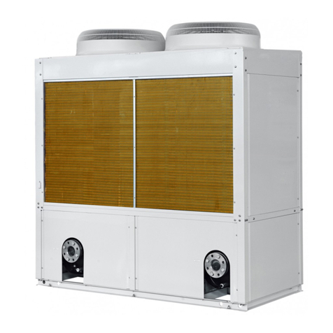
Gree LSQWRF35VM/NhA-M User manual

Change for life
Service Manual
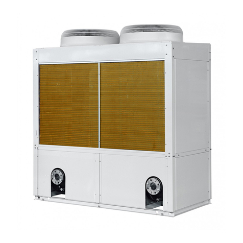
A series modular air-cooled chiller (heat pump)
LSQWRF35VM/NhA-M
LSQWRF60WM/NhA-M

Contents
1 Product information ........................................................................................3
1.1 Introduction .............................................................................................3
1.1.1 Lineup .............................................................................................3
1.1.2 Nomenclature ..................................................................................3
1.1.3 Product features ..............................................................................4
1.1.4 Nominal operating conditions ..........................................................4
1.1.5 Operation range ..............................................................................5
1.2 Performance correction curves ...............................................................5
1.3 Working principle ....................................................................................6
1.4 Technical parameters ..............................................................................8
1.4.1 Electrical parameters ......................................................................8
1.4.2 Performance parameters ................................................................9
1.4.3 Scope of supply ............................................................................11
2 Unit control ...................................................................................................13
2.1 Schematic diagram ...............................................................................13
2.2 Operation flowchart ...............................................................................15
2.2.1 Cooling ..........................................................................................15
2.2.2 Heating .........................................................................................16
2.3 Key control logics ..................................................................................17
2.3.1 Cooling control ..............................................................................17
2.3.2 Heating control ..............................................................................17
2.3.3 Control to the compressor .............................................................18
2.3.4 Control to the fan ..........................................................................18
2.3.5 Control to the 4–way valve ............................................................18
2.3.6 Control to the water pump .............................................................18
2.3.7 Control to the electric expansion valve ..........................................18
2.3.8 Protection ......................................................................................18
2.4 Introduction to controller .......................................................................19
2.5 Smart management system ..................................................................19
2.5.1 Long-distance monitoring/BMS interface ......................................19

2.5.2 Network of the long-distance monitoring system ...........................19
2.5.3 Hardware ......................................................................................20
2.5.4 Model selection instructions ..........................................................21
3 Unit installation ............................................................................................23
3.1 Installation flowchart .............................................................................23
3.2 Preparations before installation ............................................................24
3.2.1 Precautions for installation ............................................................24
3.2.2 Importance of installation ..............................................................25
3.3 Installation instructions .........................................................................26
3.3.1 Outline dimensions .......................................................................26
3.3.2 Precautions for installation ............................................................28
3.3.3 Installation environment ................................................................28
3.3.4 Installation and service space .......................................................28
3.3.5 Installation foundation ...................................................................29
3.3.6 Handling and lifting .......................................................................29
3.3.7 Placement of the main unit ............................................................30
3.4 Piping and insulation .............................................................................30
3.4.1 Installation of the water system .....................................................30
3.4.2 Requirements on piping ................................................................32
3.4.3 Installation of the expansion tank ..................................................34
3.4.4 Installation of condensate pipes ....................................................35
3.5 Electrical connection .............................................................................37
3.5.1 Safety precautions ........................................................................37
3.5.2 External connection ......................................................................37
3.5.3 Specification of power supply ........................................................41
3.5.4 Wiring of the electric control cabinet .............................................41
3.5.5 Field wiring ....................................................................................43
3.5.6 Networking and wiring between units ............................................45
3.5.7 Jumpers ........................................................................................47
4 Test operation, troubleshooting and maintenance .......................................49
4.1 Commissioning .....................................................................................49

4.1.1 Flowchart of commissioning ..........................................................49
4.1.2 Safety precautions for commissioning ...........................................49

4.1.3 Preparation before commissioning ................................................49
4.1.4 Check before commissioning ........................................................49
4.1.5 Check for initial run .......................................................................50
4.2 Troubleshooting ....................................................................................52
4.2.1 Diagnostics ...................................................................................52
4.2.2 Flow chart of troubleshooting ........................................................54
4.3 Power distribution .................................................................................60
4.3.1 Power distribution logic .................................................................60
4.3.2 Introduction to main electric elements ...........................................60
4.3.3 Main board ....................................................................................61
4.4 Replacement of main parts ...................................................................63
4.4.1 Brief introduction ...........................................................................63
4.4.2 Replacement instructions ..............................................................64
4.5 Routine maintenance ............................................................................83
4.5.1 Repairs to refrigerant leakage .......................................................83
4.5.2 Air removal ....................................................................................84
4.6 Exploded views and part lists ................................................................85
4.7 Maintenance .........................................................................................91
4.7.1 Requirements for maintenance .....................................................91
4.7.2 Freeze protection in winter ............................................................93

1
Product
Product

2
SAFETY NOTICE
The following symbols are used in this document to alert the reader to potential of hazard.
WARNING indicates a potentially hazardous situation which, if not avoided, could result in damage
to the machine as well as death or serious injury.
CAUTION identifies a hazard which could lead to minimal or moderate damage to the machine as
well as death or serious injury.
BAN indicates a potentially hazardous situation which, if not avoided, could result in death or
serious injury.
COMPLIANCE identifies a hazard which could lead death or serious injury as well as damage to the
property.
PREFACE
Thank you for selecting Gree’s A Series Inverter Modular Air-cooled Chiller (Heat Pump). Please read
this instruction manual carefully before installing and using the product, we hereby instruct as below:
This Manual is applied to A Series Inverter Modular Air-cooled Chiller (Heat Pump), specifying
operation safety requirements, basic principles and implementation approaches for construction fulfillment,
construction debug, after-sale maintenance and repairs. All works must be performed in accordance with
the relevant national (and local) safety requirements and User's Manual, which if not abided, could result
in potential damage to the air conditioner, and even serious injury or death.

3
Product
1 Product information
1.1 Introduction
1.1.1 Lineup
Model
Cooling
capacity
Heating
capacity Power
supply Refrigerant Appearance
kW kW
LSQWRF35VM/NaA-M 32 36
380–415VAC
3Ph 50Hz
LSQWRF60VM/NaA-M 60 65 R32
1.1.2 Nomenclature
LS QW R F 60 V M / Na A - M
1234567 89 10
No. Code description Options
1Unit LS: chiller
2Compressor type QW: hermetic scroll/rotary type
3Unit function Omit: cooling only
R: heat pump
4Cooling method of condenser F: air-cooled
5Rated cooling capacity Rated cooling capacity = number (kW)
6System type Omit: fixed frequency, V: variable
frequency
7Assembly method M: modular
8Refrigerant type Na: R410A, Nh: R32
9Design code A-Z alphabetic order
10 Power code M: 380–415VAC 3Ph 50Hz
For instance, LSQWRF60VM/NaA-M indicates an inverter modular air-cooled chiller with a fully
enclosed rotor-type compressor, featuring 60kW cooling capacity and using R410A refrigerant.
LSQWRF35VM/NhA-M indicates an inverter modular air-cooled chiller with a fully enclosed rotor-type
compressor, featuring 35kW cooling capacity and using R32 refrigerant.

4
1.1.3 Product features
The all-inverter modular air-cooled chillers work outstandingly by virtue of their major features stated
below.
(1) Excellent compatibility
The modular air-cooled chillers can be constructed of multiple single units with the same or different
structure or capability (35kW, 60kW,). For the 35kW unit, it has only one cooling system; for the 60kW,
65kW units, they are of two independent systems. Up to 16 single units can be modularized, with cooling
capacity ranging from 35kW to 1040kW.
(2) Comfort and energy saving
The inverter can quickly respond to load change and lead to decreased water temperature fluctuation
and better comfort.
(3) Ultra quiet operation
The high-efficiency and low-noise fan blades and motor as well as the optimized air passage can
greatly lower operation noise of the unit. Besides, the quite mode can provide the user a ultra-quiet
environment.
(4) Powerful self-protection
It is equipped with the top-end microcomputer control system which is capable of providing well-
rounded protection and self-diagnosis.
(5) High reliability
It is constructed of well-designed refrigeration parts and well-designed system, structure and electric
control, adequately guaranteeing reliable operation.
(6) Remote ON/OFF
The unit can be started or stopped by the ON/OFF key operation.
(7) Equilibrium running
It indicates each compressor will run alternately so as to extend their service life.
(8) Shiftwork of water pumps
Two water pumps can work alternately with equilibrium runtime so as to extend their service life and
lower the maintenance difficulty.
1.1.4 Nominal operating conditions
Item
Water side Air side
Water ow
m3/(h·kW) Outlet temperature (°C) Dry bulb
temperature (°C)
Wet bulb
temperature (°C)
Cooling 0.172 7 35 -
Heat pump 45 7 6

5
1.1.5 Operation range
The unit should work within the specified operation range as shown in the table below:
Item
Water side Air side
Leaving water
temperature (°C)
Water temperature
difference (°C)
Ambient DB
temperature (°C)
Cooling 5~20 2.5~6 -15~52
Heating 35~50 2.5~6 -20~40
Maximum and minimum entering water pressures
Item Minimum entering water pressure Maximum entering water pressure
Cooling 0.06MPa 1.6MPa
Heating
1.2 Performance correction curves
Here are curves indicating the unit performances in cooling and heating states.
Leaving water temperature (°C)
Capacity (kW)
Ambient temperature (°C)
Capacity (kW)
Ambient temperature (°C)
LSQWRF35VM/NaA-M, LSQWRF35VM/NhA-M
Cooling
LSQWRF35VM/NaA-M, LSQWRF35VM/NhA-M
Heating
Leaving water temperature (°C)
Capacity (kW)
Ambient temperature (°C)
Capacity (kW)
Ambient temperature (°C)
LSQWRF60VM/NaA-M, LSQWRF60VM/NhA-M
Cooling
LSQWRF60VM/NaA-M, LSQWRF60VM/NhA-M
Heating

6
◆R32: LSQWRF35VM/NhA-M
High-pressure switch
COOL
HEAT
Discharge temp.sensor
Compressor
4-way valve
Finned heat exchanger
Electric expansion valve
Vapor-liquid separator
High pressure sensor
Defrosting
temp.
Suction
temp.
Leaving water
temp.s ensor
Capillary tube
Solenoid valve
Stop valve
Stop valve
Water flow
switch
Shell-an d-t ube heat exchanger
Low-pressure switch for heating
Low-pressure switch for cooling
sensor
sensor
Safety valve
Ambient
temp. sensor
Freeze protection
temp. sensor
Entering water
temp. sensor
Shell-and-tube
outlet temp. sensor
Shell-and-tube
inlet temp. sensor
1.3 Working principle
Here are diagrams below to present the constituents and refrigerant flow of the system.
Product

7
Product
◆R32: LSQWRF60VM/NhA-M
Stop valve
Stop valve
Stop valve
Safety valve
Fan
Vapor liquid separator Vapor liquid separator
Low-pressure switch
for cooling
Low-pressure switch
for heating
Compressor
Discharge temp. sensor
High-pressure sensor
Low-pressure switch
for cooling
Low-pressure switch
for heating
Compressor
Discharge temp. sensor
High-pressure sensor
High-pressure switch
4-way valve
High-pressure switch
4-way valve
Finned heat exchanger
Fan
Finned heat exchanger
Capillary tube Capillary tubeSolenoid valve Solenoid valve
Defrosting
temp. sensor
COOL
HEAT
Shell-and-tube inlet
temp. sensor
Shell-and-tube inlet
temp. sensor
Defrosting
temp. sensor
Ambient temp. sensor
Entering water temp. sensor Leaving water temp. sensor
Freeze protection
temp. sensor
Shell-and-tube heat exchanger
Shell-and-tube inlet
temp. sensor
Shell-and-tube inlet
temp. sensor
Suction
temp. sensor
Suction
temp. sensor
Safety valve
Water flow switch

8
1.4 Technical parameters
1.4.1 Electrical parameters
Electrical data table
Model Power supply Compressor
quantity MRC (A) NRC (A) Fan
quantity NRC (A)
LSQWRF35VM/NhA-M 380V-415V AC
3Ph 50Hz 1 22 19.2 2 0.70
LSQWRF60VM/NhA-M 380V-415V AC
3Ph 50Hz 2 52 32.9 2 1.28
Notes:
(a) MRC: maximum running current (A)
(b) NRC: nominal running current (A)

9
1.4.2 Performance parameters
Model LSQWRF35VM/NaA-M LSQWRF60VM/NaA-M
Cooling capacity kW 32 60
Heating capacity kW 36 65
Rated cooling power kW 12.4 21.9
Rated heating power kW 10.8 20.2
Sound level dB(A) 62 68
Power supply 380–415V AC 3Ph 50Hz
Operation control The microcomputer implementing fully automatic control, displaying
the operation state and giving an alarm
Safety controls
High-pressure and low-pressure safety cut-out, high-discharge
temperature cutout, freeze protection, overflow control, phase safety
device, water flow safety control, pressure sensor cutout, temperature
sensor cutout, four-way valve safety control, compressor overheating
control
Compressor
Type Fully enclosed rotor-type compressor
Quantity 1 2
Starting mode With variable frequency
Water-side heat
exchanger High-efficiency shell and tube heat exchanger
Water flow
volume m3/h 5.5 10.32
Water
resistance kPa 75 55
The highest
bearing
pressure
MPa 4.6
Connection
method By external threads
Connection thread G1 1/2 external thread G2 external thread
Air side
Air-side heat
exchanger High-efficiency finned coil heat exchanger
Rated power
of fan W 750×2 750×2
Airflow
volume m3/h 1.26×1041.26×104
Outline
dimension
Width mm 1340 2200
Depth mm 845 965
Height mm 1605 1675
Net weight mm 400 689
Operating weight kg 400 758

10
Model LSQWRF35VM/NhA-M LSQWRF60VM/NhA-M
Cooling capacity kW 32 60
Heating capacity kW 35 65
Rated cooling power kW 11.7 20.8
Rated heating power kW 10.6 19.9
Sound level dB(A) 62 68
Power supply 380–415V AC 3Ph 50Hz
Operation control The microcomputer implementing fully automatic control, displaying the
operation state and giving an alarm
Safety controls
High-pressure and low-pressure safety cut-out, high-discharge
temperature cut-out, freeze-up control, overflow control, phase safety
device, water flow safety control, pressure sensor cutout, temperature
sensor cutout, four-way valve safety control, compressor overheating
control
Compressor
Type Fully enclosed rotor-type compressor
Quantity 1 2
Starting mode With variable frequency
Water-side heat
exchanger High-efficiency shell and tube heat exchanger
Water flow
volume m3/h 5.5 10.32
Water
resistance kPa 80 55
The highest
bearing
pressure
MPa 4.6
Connection
method By external threads
Connection
thread G1 1/4 external thread G2 external thread
Air side
Air-side heat
exchanger High-efficiency finned coil heat exchanger
Rated power
of fan W 750×2 750×2
Airflow
volume m3/h 2×0.63×1042×1.2×104
Outline
dimension
Width mm 1340 2200
Depth mm 845 965
Height mm 1605 1675
Net weight mm 405 686
Operating weight kg 445 755

11
1.4.3 Scope of supply
Item Heat pump
Modules S
Three-wire control lines (8m) S
Accessories for the unit XE73-25/G S (Additionally purchased)
Electric control cabinet O
Auxiliary electric heater O
Power lines O
Control lines O
Connecting hose O
Thermometer O
Pressure gauge O
S= standard; O= field-supplied; P= optional

12
Unit Control
Unit Control

13
Unit Control
2 Unit control
2.1 Schematic diagram
Anti-freezing and over-temperature sensor
Input
Description:
(1) A water flow cutout is used to judge the water flow rate. When the flow rate is too low, it will trip off,
and the control board will send this signal to the display and the water pump. Then, the display will
tell there is an error, the water pump will stop and the unit will stop or will not start.
(2) A high/low pressure cutout is used to judge the system pressure. When the system pressure is too
high/low, it will trip off, and the control board will send this signal to the display. Then, the display
will tell there is an error and the unit will stop or will not start.
(3) An ambient temperature sensor is used to detect the temperature of the environment where the
unit is which will determine whether to start or stop the fan and determine the steps of the electric
expansion valve when initializing. When this sensor fails, the control board will detect and send this
signal to the display. Then, the display will tell there is an error and the unit will stop or will not start.
(4) A discharge temperature sensor is used to detect the discharge temperature. When the sensed
temperature is too high or this sensor fails, the control board will detect and send this signal to the
display. Then, the display will tell there is an error and the unit will stop or will not start.

14
Unit Control
(5) An entering water temperature sensor is used to detect the temperature of the entering water which
will determine whether to start or stop the compressor and the auxiliary electric heater. When this
sensor fails, all compressors of the unit will stop.
(6) Defrost temperature sensor is used to detect the liquid tube temperature of fins serving the
condenser, which will determine whether to start the fan. When the sensed temperature is too
high or this sensor fails, the control board will detect and send this signal to the display. Then, the
display will tell there is an error and the unit will stop or will not start.
(7) An anti-freezing and overheating prevention temperature sensor is used to detect the water
temperature. When it fails, compressors and fans of the corresponding unit will stop.
(8) A leaving water temperature sensor is used to detect the leaving water temperature. When this
sensor fails, compressors and fans of the corresponding unit will stop.
(9) An air temperature sensor on shell-and-tube heat exchanger is used to detect the air temperature.
When this sensor fails, the compressor in a cooling state will have to be stopped and the display
will tell there is an error. If the sensor fails in a heating state, only the display will tell an error.
(10) An liquid temperature sensor on shell-and-tube heat exchanger is used to detect the liquid
temperature. When this sensor fails, the compressor in a cooling state will have to be stopped and
the display will tell there is an error. If the sensor fails in a heating state, only the display will tell an
error.
(11) A suction temperature sensor is used to detect the suction temperature. When this sensor fails, the
compressor in a cooling state will have to be stopped and the display will tell there is an error. If the
sensor fails in a heating state, only the display will tell an error.
(12) High-pressure sensor is used to detect the discharge pressure. When the detected temperature is
too high, control the compressor to regulate the frequency of discharge.

15
Unit Control
2.2 Operation owchart
2.2.1 Cooling
Yes
Yes
open
Is system 1 ready to
start compressors?
Is system 1 ready to
stop compressors?
EXV for cooling mode
is in timer control.
EXV for cooling mode
is reset.
Compressor 1 stops.

16
2.2.2 Heating
Yes
Yes
Yes
open
Is system 1 ready to
start compressors?
EXV for heating mode
is in timer control.
EXV for heating mode
is reset.
Is system 1 ready to
stop compressors?
This manual suits for next models
1
Table of contents
Other Gree Chiller manuals

Gree
Gree LSQWRF35VM/NaA-M User manual

Gree
Gree A Series User manual

Gree
Gree C Series User manual

Gree
Gree T1/R410A/50Hz User manual

Gree
Gree HLR8WZNa-M User manual

Gree
Gree D Series User manual

Gree
Gree B Series User manual

Gree
Gree GK-C03TC1AD User manual

Gree
Gree LSQWF65M/N-M User manual

Gree
Gree D Series User manual