Table of contents
Components of the ATB set................................................................................................................... 3
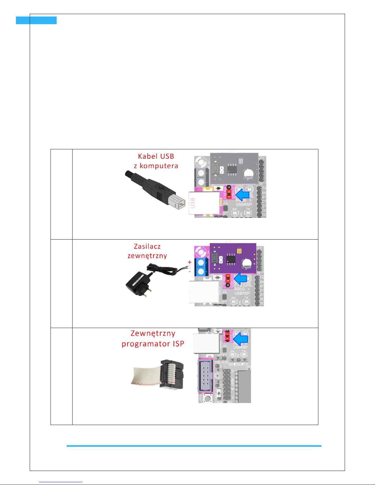
Methods of power supply...................................................................................................................... 4
First run - testing the set........................................................................................................................ 5
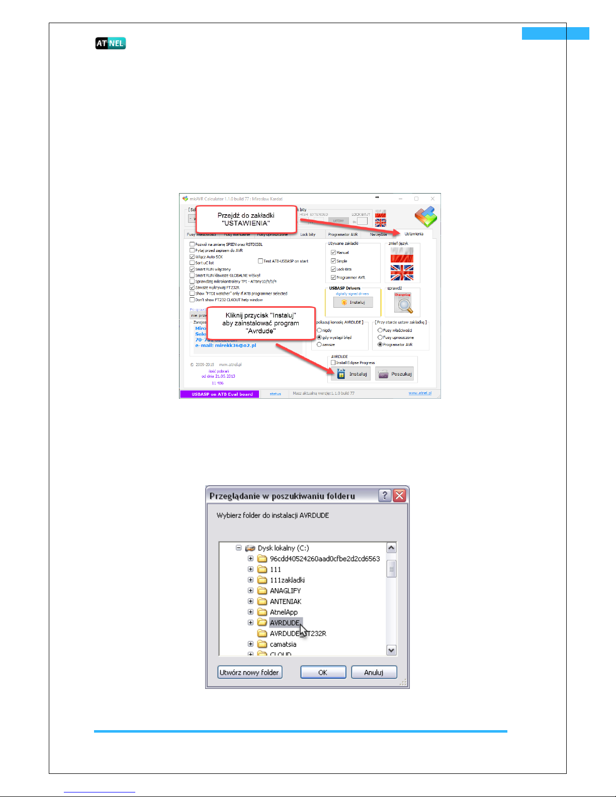
AVRDUDE –installation, first steps with MkAvrCalculator.............................................................. 5
MkAvrCalculator software - license................................................................................................... 6
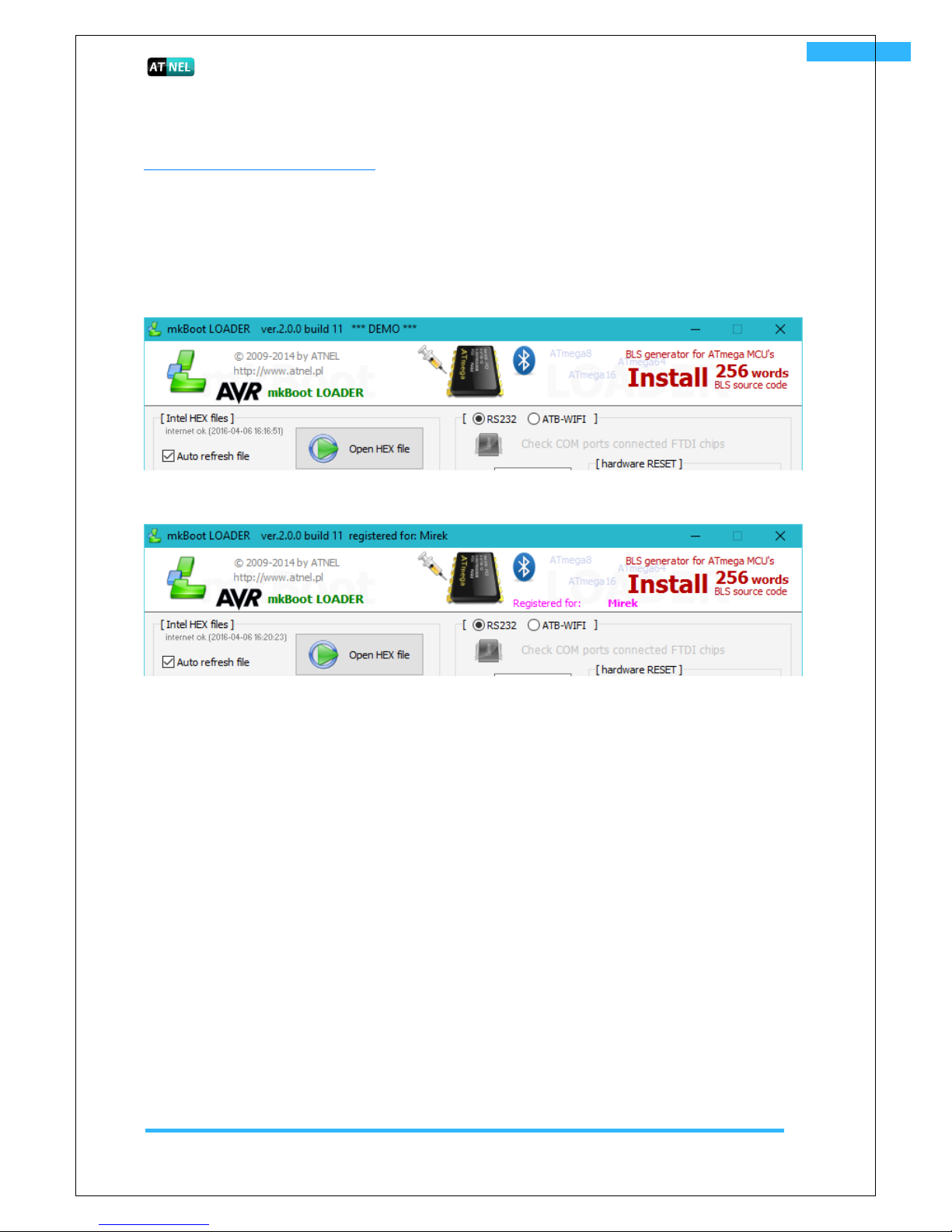
MkBootloader software - license ...................................................................................................... 7
Build-in ATB-USBasp programmer .................................................................................................... 8
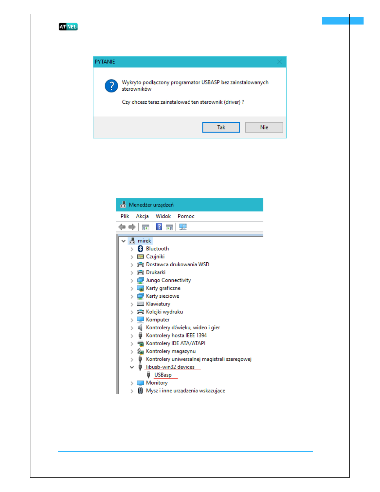
Installing drivers for build-in USBasp programmer ..................................................................... 8
ATB set fusebit settings ....................................................................................................................10
BLS reading- first test of proper operation of the microcontroller.................................................11
Testing the set....................................................................................................................................11
Jumpers in the ATB set ......................................................................................................................... 12
General scheme of the ATB set ............................................................................................................16
Microcontrollers in the ATB set........................................................................................................... 20
Methods of microcontroller clocking................................................................................................... 21
Connector of the ISP - KANDA programmer (internal / external programmer)................................22
Methods of microcontroller RESET......................................................................................................23
LCD display 2x16cz.................................................................................................................................25
OLED display - I2C ................................................................................................................................. 26
7-segment LED display - 4 positions .................................................................................................... 26
LED diodes –8 pieces............................................................................................................................27
IR diode transmitter (infrared).............................................................................................................27
Infrared receiver (TSOP31236) and TSMP58000 (IR carrier) ............................................................. 28
Digital temperature sensor DS18B20 .................................................................................................. 28
Buzzer (loudspeaker)........................................................................................................................... 29
Buttons (key buttons) tact-switch type.............................................................................................. 29
External EEPROM memory - 24c04e ................................................................................................... 30
RS485 - SN75176 integrated circuit (MAX485) equivalent ................................................................ 30
RS485 –transmission and PC control............................................................................................... 31
USB adapter / RS232 / RS485 ................................................................................................................33
Scheme of the adapter and connections........................................................................................ 34