ATO AM2011 User manual

Humidity Sensor, Capacitive
AM2011 User Manual

User Manual AM2011
- 1 -
.
1. Product Overview
AM2011 is a humidity sensitive capacitive temperature and humidity sensor, and the sensor
signal adopts the analog voltage output method. This module has high precision, high reliability,
good consistency, and with temperature compensation, to ensure good long-term stability, easy
to use and low price, especially suitable for enterprises with strict quality and cost
requirements.
2. Applications
It is suitable for HVAC, humidifier, dehumidifier, communication, atmospheric environment monitoring,
industrial process control, agriculture, measuring instrument, etc.
3. Features
Low power consumption, small size, with temperature compensation, single-chip calibration linear
output, easy to use, low cost, completely interchangeable, long signal transmission distance,
accurate calibration.
4. Dimension (Unit:mm)

User Manual AM2011
- 2 -
5.Interface Definition
5.1 Pin Assignment
Table 1:Pin Assignment
5.2 Power Pin (VDD GND)
The power supply voltage of this module is 3.3V~5.5V, and the recommended voltage is 5.0V.
5.3 Voltage output signal line (Hout)
The humidity signal is output in the form of voltage from this signal line, and the voltage output range is 0-3V. For the
specific relationship between humidity and voltage, please refer to the voltage and humidity characteristic table (Table 6).
5.4 Temperature output signal line (Tout)
The temperature sensor is a 10K NTC B.3435 thermistor instead of an analog signal output. The user needs to add a
reading circuit, and the temperature measurement range is -40~80℃.
5.5 Wiring diagram of temperature sensor
Figure 2: Temperature wiring diagram
Pin Color Name Description
1Red VDD Power Supply(3.3V-5.5V DC)
2Yellow Hout Humidity Output(0-3V DC)
3Black GND Ground Wire
4White Tout Temperature is NTC10K
thermistor
Figure 1: Pinout Diagram

User Manual AM2011
- 3 -
6. Sensor performance
6.1 Relative humidity
Table 2: Relative Humidity Performance Table
6.2 Maximum error of relative humidity (25℃)
Figure 3: Maximum relative humidity error at 25°C
6.3 Temperature
The temperature sensor is an NTC 10K thermistor. The temperature sensor parameters are shown in Table 3.
Table 3: 10K NTC B.3435 technical parameters
Model
Rated zero power
resistance value(R25)
B
(K)
Dissipation
coefficient
(mw/℃)
Thermal time
constant
(S)
Rated power
(mw)
Range of working
temperature
(℃)
CN0603R103B3435FT 10KΩ3435 ≥2.5 ≤18 150 -40~80
Parameter Condition Min Typ Max Unit
Measuring range 0 99.9 %RH
Precision[1] 25℃±3 %RH
Repeatability ±1 %RH
Interchangeability Fully Interchangeable
Response time[2] 1/e(63%) <5 S
Delaying ±0.3 %RH
Drift[3] Typical value <0.5 %RH/yr
[1] This accuracy is the accuracy index tested at
25°C and 5V when the sensor is tested at the
factory. It does not include hysteresis and
nonlinearity, and is only suitable for non-
condensing environments.
[2] The time required to reach 63% of the first-
order response at 25°C and 1m/s airflow.
[3] Values may be higher in volatile organic
compounds.

User Manual AM2011
- 4 -
.
7. Electrical Characteristics
Electrical characteristics, such as energy consumption, input, output voltage, etc., all depend on the power supply. Table
5 details the electrical characteristics of the sensor, if not marked, it means the supply voltage is 5V. To get the best
results with the sensor, please strictly follow the conditions in Table 5 when designing.
Table 5: AM2011 sensor DC characteristics
Parameter Condition Min TypMax Unit
Supply voltage 3.3 5.0 5.5 V
Humidity voltage output range 0 3 V
Power consumption Measurement 1.5 mA
Humidity Sampling Period 2.5 S
Operating temperature range 0 80 ℃
Measuring temperature range NTC 10K -40 80 ℃
Temperature output NTC 10K - - - -
7.1 Standard humidity output voltage (without debugging) (condition: at 25℃, Vin=5.0V) Unit: V
Table 6: AM2011 Standard Humidity Output Voltage Correspondence Table
Relative humidity(%RH) 0 10 20 30 40 50 60 70 80 90 100
Output voltage (V) 0 0.3 0.6 0.9 1.2 1.5 1.8 2.1 2.4 2.7 3.0
Full-scale temperature compensation, full-scale microcontroller calibration output, output impedance: below 5kΩ.
7.2 Relationship between humidity and output voltage
Humidity conversion formula: Humidity = Voltage (output voltage) ÷ 0.03 ( %RH)
7.3 Linear curve of voltage output and humidity
The humidity measurement range of the sensor is 0-100%RH, and the voltage output is 0.0-3.0V. The linear
relationship between voltage and humidity is shown in Figure 5:
Figure 6: Linear Curve of Voltage Output vs. Humidity

User Manual AM2011
- 5 -
. .
7.6 NTC10K Thermistor Temperature Corresponding Resistance Table
Standard temperature output resistance (no debugging)
Table 8: 10K NTC B.3435 temperature and resistance corresponding table
Temperature(℃) 0 10 20 30 40 50 60 70 80
Resistance(kΩ) 27.90 18.22 12.12 8.31 5.80 4.12 3.00 2.21 1.66
8. Standard testing conditions
In the atmosphere, the temperature is 25°C and the supply voltage is 5.0V DC as a reference. For characteristic
measurement, put the temperature and humidity module into dry air at 25°C/0%RH for 5 minutes before the
measurement, and the humidity generating device generates a humidity of 60%RH, put it into the temperature and
humidity module for 5 minutes, and measure the voltage value.
9. Stability test
No. Project Experiment Method Specification Value
1Impact
resistance Repeat 3 natural drops from a height of 1m on a hard floor. No damage, component desoldering
electrical characteristics are normal.
2Vibration
resistance
The frequency is 10~55Hz, the amplitude is 1.5mm (10~55Hz~10Hz), and
the vibration test is performed in the X-Y-Z directions for 2 hours each.
No damage, component desoldering
electrical characteristics are normal.
3Heat resistance Place in the air at a temperature of 80°C and a humidity of 30%RH or
less for 1000 hours. Within±3%RH
4Cold resistance Place in the air with a temperature of 10°C and a humidity of 70%RH
or less for 1000 hours. Within±3%RH
5Moisture
resistance 1000 hours in air at a temperature of 40°C and a humidity of 90%RH. Within±3%RH
6Temperature
cycle
Place at 0°C for 30 minutes, then transfer to 50°C for 30 minutes, and
then place at 0°C for 30 minutes, repeating 5 times. Within±3%RH
7Resistant to
organic solvents
Room temperature organic solvent Ethanol gas (30 minutes), acetone
gas (30 minutes) Within±3%RH
Note 1) The specification value is based on 60%RH humidity change amount.
Note 2) After each test is completed, the humidity module is placed in normal air with
normal temperature and humidity for 4 hours, and the change in humidity is measured.
Note: 10kΩ NTC See attached table for details: Resistance-Temperature Characteristics Table

User Manual AM2011
- 6 -
- . -
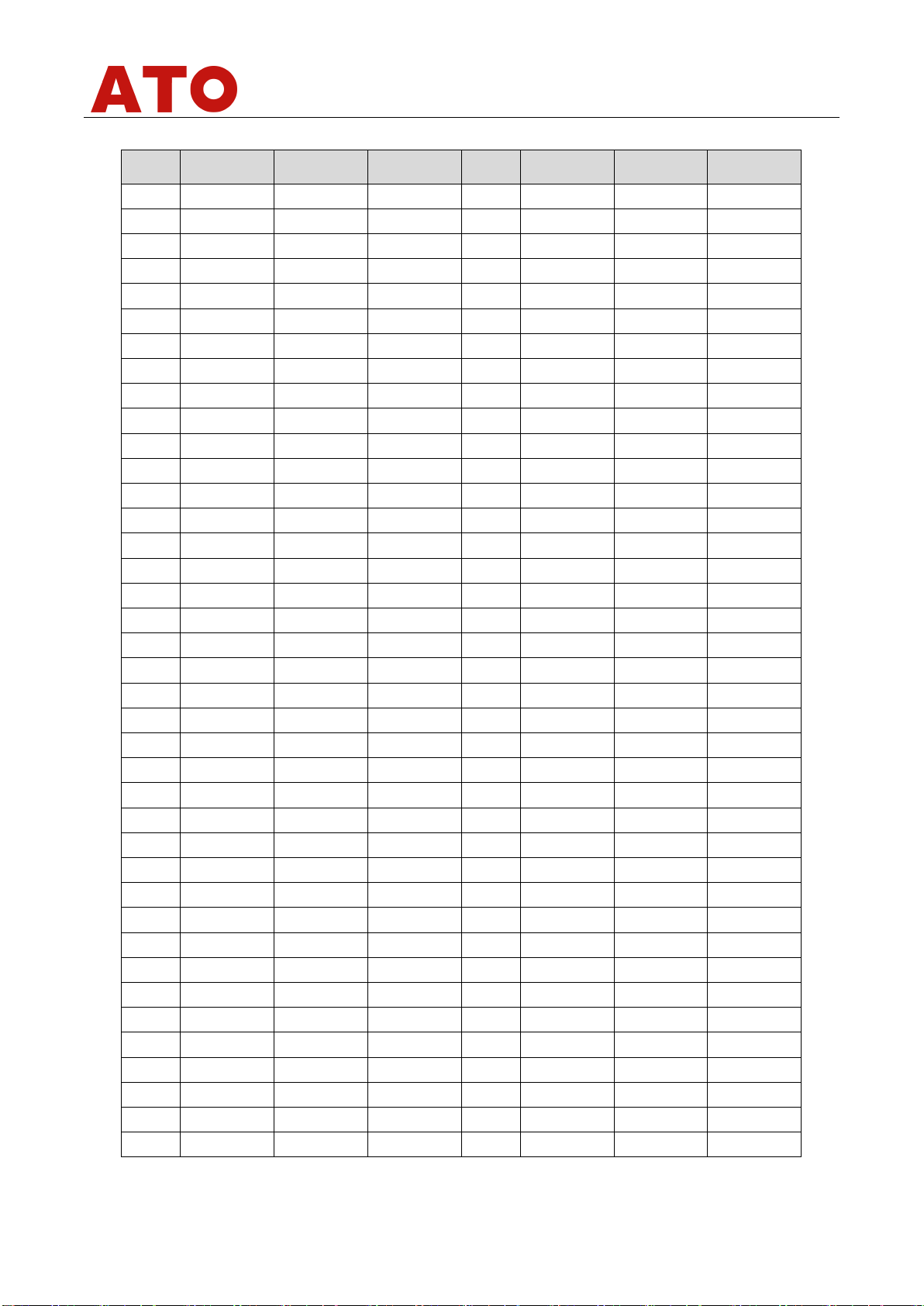
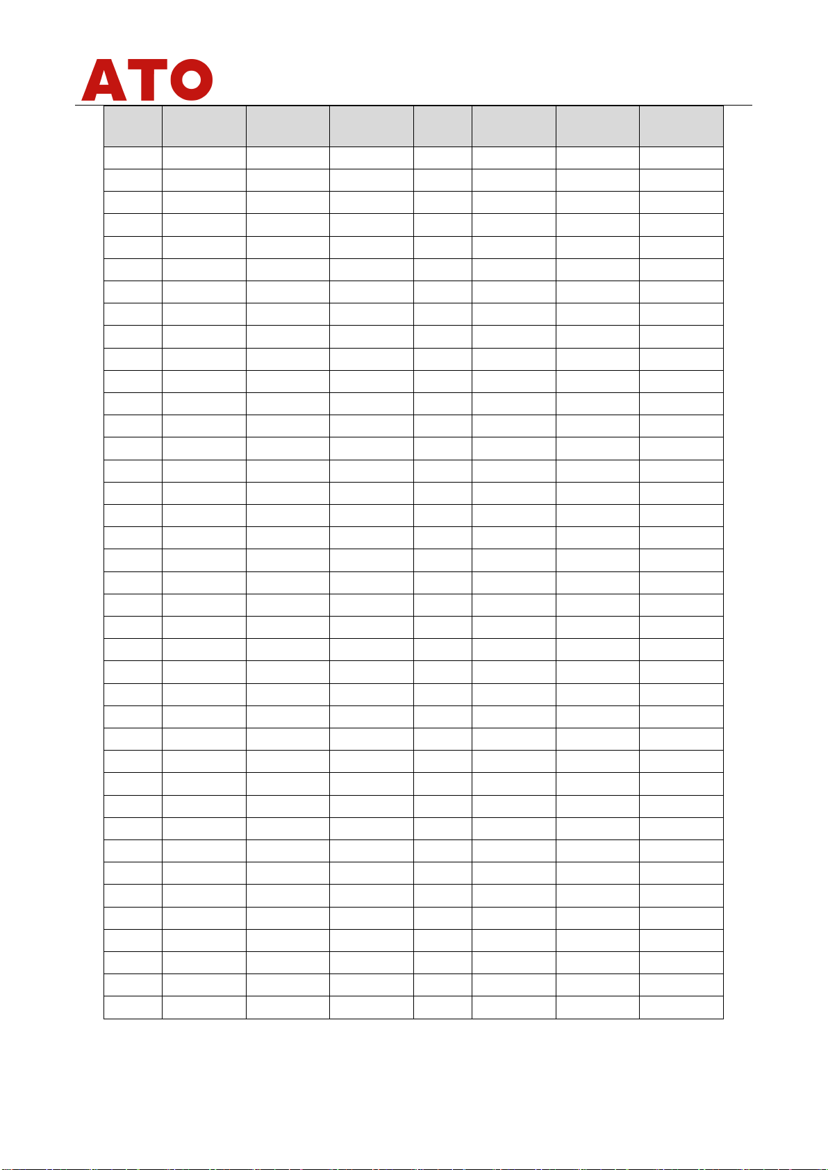
Attached table NTC 10K resistance-temperature characteristic table
T(℃) RMin(KΩ) RNor(KΩ) RMax(KΩ) T(℃) RMin(KΩ) RNor(KΩ) RMax(KΩ)
-40 218.9971 228.2376 237.8441 -1 28.9630 29.5745 30.1959
-39 206.2948 214.8696 223.7783 0 27.6951 28.2671 28.8480
-38 194.4226 202.3826 210.6475 1 26.4908 27.0257 27.5687
-37 183.3204 190.7126 198.3831 2 25.3463 25.8466 26.3542
-36 172.9331 179.8005 186.9219 3 24.2585 24.7264 25.2008
-35 163.2098 169.5919 176.2059 4 23.2242 23.6617 24.1051
-34 154.1034 160.0366 166.1815 5 22.2404 22.6495 23.0638
-33 145.5707 151.0884 156.7995 6 21.3044 21.6869 22.0739
-32 137.5716 142.7046 148.0144 7 20.4136 20.7711 21.1327
-31 130.0693 134.8459 139.7840 8 19.5655 19.8996 20.2373
-30 123.0294 127.4759 132.0698 9 18.7578 19.0700 19.3854
-29 116.4204 120.5608 124.8359 10 17.9884 18.2801 18.5746
-28 110.2132 114.0696 118.0492 11 17.2553 17.5276 17.8025
-27 104.3805 107.9735 111.6791 12 16.5564 16.8108 17.0673
-26 98.8973 102.2459 105.6972 13 15.8901 16.1275 16.3668
-25 93.7405 96.8620 100.0775 14 15.2547 15.4762 15.6994
-24 88.8883 91.7990 94.7955 15 14.6484 14.8550 15.0631
-23 84.3209 87.0357 89.8288 16 14.0699 14.2625 14.4564
-22 80.0197 82.5523 85.1565 17 13.5176 13.6972 13.8778
-21 75.9675 78.3306 80.7593 18 12.9903 13.1576 13.3257
-20 72.1481 74.3538 76.6191 19 12.4867 12.6425 12.7989
-19 68.5468 70.6058 72.7194 20 12.0056 12.1505 12.2960
-18 65.1498 67.0723 69.0446 21 11.5459 11.6806 11.8158
-17 61.9440 63.7394 65.5803 22 11.1064 11.2316 11.3571
-16 58.9176 60.5946 62.3132 23 10.6862 10.8025 10.9190
-15 56.0594 57.6261 59.2307 24 10.2844 10.3923 10.5002
-14 53.3589 54.8228 56.3212 25 9.9000 10.0000 10.1000
-13 50.8065 52.1745 53.5741 26 9.5249 9.6248 9.7248
-12 48.3931 49.6717 50.9791 27 9.1662 9.2658 9.3656
-11 46.1103 47.3056 48.5269 28 8.8230 8.9223 9.0218
-10 43.9502 45.0676 46.2088 29 8.4946 8.5934 8.6925
-9 41.9055 42.9503 44.0166 30 8.1803 8.2786 8.3772
-8 39.9693 40.9462 41.9428 31 7.8794 7.9770 8.0750
-7 38.1351 39.0487 39.9801 32 7.5913 7.6882 7.7855
-6 36.3970 37.2514 38.1219 33 7.3153 7.4114 7.5080
-5 34.7494 35.5484 36.3621 34 7.0509 7.1461 7.2419
-4 33.1869 33.9342 34.6949 35 6.7976 6.8919 6.9867
-3 31.7047 32.4037 33.1148 36 6.5547 6.6480 6.7420
-2 30.2982 30.9520 31.6167 37 6.3219 6.4142 6.5072

User Manual AM2011
- 7 -
T(℃) RMin(KΩ) RNor(KΩ) RMax(KΩ) T(℃) RMin(KΩ) RNor(KΩ) RMax(KΩ)
38 6.0986 6.1899 6.2818 82 1.5032 1.5469 1.5918
39 5.8845 5.9746 6.0655 83 1.4613 1.5043 1.5484
40 5.6790 5.7680 5.8578 84 1.4208 1.4630 1.5063
41 5.4818 5.5697 5.6584 85 1.3816 1.4231 1.4656
42 5.2926 5.3793 5.4669 86 1.3437 1.3844 1.4262
43 5.1109 5.1964 5.2829 87 1.3070 1.3470 1.3880
44 4.9364 5.0208 5.1060 88 1.2715 1.3107 1.3510
45 4.7688 4.8520 4.9361 89 1.2371 1.2756 1.3152
46 4.6079 4.6898 4.7727 90 1.2038 1.2416 1.2805
47 4.4532 4.5339 4.6156 91 1.1716 1.2087 1.2469
48 4.3045 4.3840 4.4645 92 1.1404 1.1768 1.2143
49 4.1616 4.2398 4.3191 93 1.1101 1.1459 1.1827
50 4.0242 4.1012 4.1793 94 1.0808 1.1159 1.1520
51 3.8920 3.9678 4.0447 95 1.0524 1.0868 1.1223
52 3.7649 3.8395 3.9152 96 1.0248 1.0587 1.0936
53 3.6426 3.7160 3.7905 97 0.9981 1.0314 1.0656
54 3.5249 3.5971 3.6704 98 0.9723 1.0049 1.0385
55 3.4116 3.4826 3.5547 99 0.9472 0.9792 1.0123
56 3.3025 3.3724 3.4433 100 0.9228 0.9543 0.9868
57 3.1975 3.2662 3.3360 101 0.8992 0.9302 0.9620
58 3.0964 3.1639 3.2325 102 0.8764 0.9067 0.9380
59 2.9990 3.0654 3.1328 103 0.8542 0.8840 0.9147
60 2.9052 2.9704 3.0367 104 0.8326 0.8619 0.8921
61 2.8148 2.8788 2.9440 105 0.8117 0.8405 0.8702
62 2.7276 2.7905 2.8547 106 0.7914 0.8197 0.8488
63 2.6436 2.7054 2.7684 107 0.7717 0.7995 0.8281
64 2.5626 2.6233 2.6853 108 0.7526 0.7799 0.8080
65 2.4845 2.5442 2.6050 109 0.7341 0.7608 0.7885
66 2.4091 2.4678 2.5276 110 0.7161 0.7423 0.7695
67 2.3365 2.3940 2.4528 111 0.6986 0.7244 0.7511
68 2.2663 2.3229 2.3806 112 0.6816 0.7069 0.7332
69 2.1987 2.2542 2.3109 113 0.6650 0.6900 0.7158
70 2.1334 2.1879 2.2436 114 0.6490 0.6735 0.6988
71 2.0703 2.1239 2.1786 115 0.6334 0.6575 0.6824
72 2.0094 2.0620 2.1158 116 0.6183 0.6419 0.6664
73 1.9506 2.0023 2.0551 117 0.6036 0.6268 0.6508
74 1.8938 1.9446 1.9964 118 0.5893 0.6121 0.6357
75 1.8390 1.8888 1.9397 119 0.5754 0.5978 0.6210
76 1.7860 1.8349 1.8849 120 0.5618 0.5839 0.6067

User Manual AM2011
- 8 -
.
T(℃) RMin(KΩ) RNor(KΩ) RMax(KΩ) T(℃) RMin(KΩ) RNor(KΩ) RMax(KΩ)
77 1.7348 1.7828 1.8319 121 0.5487 0.5703 0.5928
78 1.6853 1.7324 1.7807 122 0.5359 0.5572 0.5793
79 1.6374 1.6837 1.7311 123 0.5235 0.5444 0.5661
80 1.5912 1.6366 1.6831 124 0.5114 0.5319 0.5533
81 1.5464 1.5910 1.6367 125 0.4996 0.5198 0.5408
10. Application Information
10.1 Working and storage conditions
Exceeding the sensor's recommended operating range may result in a temporary drift signal of up to 3%RH. After
returning to normal operating conditions, the sensor will slowly return to a calibrated state. See "Recovery
Processing" to speed up the recovery process. Prolonged use under abnormal working conditions will accelerate the
aging of the product.
Avoid placing components in dew condensation and dry environments and the following environments for a long
time.
A. Salt spray
B. Acid or oxidizing gas, such as sulfur dioxide, hydrochloric acid recommended storage environment
Temperature: 10~40℃ Humidity: Below 60%RH
10.2 Exposure to chemicals
The sensing layer of capacitive humidity sensors can be disturbed by chemical vapors, and the diffusion of chemicals
in the sensing layer can cause measurement drift and decrease sensitivity. In a pure environment, pollutants are
slowly released. The recovery process described below will speed up this process. High concentrations of chemical
contamination, such as ethanol, can cause complete damage to the sensing layer of the sensor.
10.3 Temperature
The relative humidity of a gas is largely dependent on temperature. Therefore, when measuring humidity, it should
be ensured that the humidity sensor works at the same temperature as possible. If sharing a printed circuit board
with electronic components that emit heat, mount the sensor as far away from the electronic components as
possible and under the heat source while maintaining good ventilation of the enclosure. To reduce heat transfer, the
sensor and other parts of the printed circuit board should have as little copper as possible, leaving a gap between
them.
10.4 Light
Prolonged exposure to sunlight or intense UV radiation can degrade performance.
10.5 Recovery processing
Sensors placed under extreme operating conditions or in chemical vapors can be restored to their calibrated state by
the following procedures. Hold at 45°C and <10%RH humidity for 2 hours (drying); then hold at 20-30°C and >70%RH
humidity for 5+ hours.
10.6 Wiring precautions
The quality of the signal wire will affect the quality of the voltage output. It is recommended to use a high-quality
shielded wire.
10.7 Welding information
For manual soldering, the contact time must be less than 3 seconds at temperatures up to 300°C.
10.8 Product upgrade
For details, please consult the ATO Electronic Technology Department.

User Manual AM2011
- 9 -
11. License Agreement
No part of this manual may be reproduced in any form or by any means, electronic or mechanical (including
photocopying), nor may its contents be communicated to third parties without the prior written permission of the
copyright holder. The contents of this instruction manual are subject to change without notice. ATO owns the
ownership of the software and the user can only use the software after signing a contract or a license to use the
software.
12. Warning and personal injury
Do not use this product in safety protection devices or emergency stop equipment, or in anyother application where
personal injury may result from failure of this product, unless there is a special purpose or authorization for use. Refer
to the product data sheet and application guide before installing, handling, using or maintaining this product. Failure to
follow this recommendation could result in death and serious personal injury. The company will not be liable for all
compensation for personal injury or death arising therefrom, and exempts any claims that may arise from company
managers and employees, as well as affiliated agents, distributors, etc., including: various costs, compensation fees,
attorney fees, etc.
13. Quality Assurance
The company provides a 3-month quality guarantee (calculated from the date of shipment) to direct purchasers of its
products. The technical specifications of the data sheet published by the company for this product shall prevail. If
within the warranty period, the product is confirmed to be defective in quality, the company will provide free repair or
replacement. Users must meet the following conditions:
1. Please send an email to the ATO within 14 days of finding the defect in this product.
2. The product should be mailed back to the ATO at the purchaser's expense.
3. The product should be within the shelf life.
ATO is only responsible for products that are defective when used in accordance with the technical conditions of the
product. ATO makes no warranties, guarantees or written representations about the use of its products in those
particular applications. At the same time, ATO does not make any promises about the reliability of its products applied
to products or circuits.
Table of contents