Atomos ZATO CONNECT User manual

ATOMOS
ZATO CONNECT
USER MANUAL
AOMOS

I/O AND PHYSICAL
FEATURES
The front of the ZATO CONNECT is almost entirely covered by its 5" SuperAtom IPS display.
On the right side of the device, you'll find the multi-purpose Power button, as well as the
ZATO CONNECT's SD Card slot.

The left side of the enclosure houses the 3.5mm Mic/Line Input jack, a!3.5mm Headphone
jack, and a 2.5mm Serial/LANC connector.
The primary I/O of the ZATO CONNECT is located at the rear of the device. It consists of two

USB-C ports (USB 1 & USB 2) on the top left and two HDMI ports (Input & Output) on the
top right.
Note: USB 1 acts as a USB UVC/webcam input, while USB 2 is a multi-purpose port
instead. It may either be used as a USB UVC/Webcam output or a connection point for the
included USB-C to Ethernet adapter.
Two SMA connectors are placed along the top and are where you want to connect the
included WiFi antennas to.
In the center, there's the NP-F/L-Series battery slot.
An additional USB-C port named USB PD is placed to the left of the battery slot. If you want
to power your ZATO CONNECT via a USB PD power adapter or a power bank, this is where
you'd connect those to.
Note: We recommend only using USB PD devices that can output a minimum of 20W.

Other physical features are the device's ventilation holes along the top and bottom edges of
the enclosure, which should not get obstructed or covered up during use. To provide
mounting flexibility, the ZATO CONNECT includes 1/4"20 threads on the top and bottom.

BATTERIES & POWER
Before you can power on the ZATO CONNECT, you first need to attach a power source to it.
This could either be an NP-F/L-Series battery, or a USB PD power bank or power adapter.!
Once these requirements are met, you can turn on the ZATO CONNECT by shortly pressing
the power button on the right side of the device. To power offthe device again, hold the
power button for ~4 seconds until the screen turns black.
You can also configure the ZATO CONNECT for redundant powering if you connect both an
USB
1
USB
2
ATOMOS
USB
PD
HamI
ATOMOS
CLOUD
STUDIC
D
I
N
H
<OUT
H
D

NP-F/L-Series battery AND a USB PD power source to it. This way, the device will
automatically switch between power sources if one of them fails to supply sufficient power.
Note: The ZATO CONNECT usually operates at ~10W during regular use, but it may draw up
to 20W of power under load. Please ensure that your USB PD power source can supply at
least 20W of power for reliable operation in any situation.
Note: Connecting the ZATO CONNECT to a USB power bank or adapter that doesn't meet
the required power output specifications may result in the ZATO not turning on or behaving
unpredictably.
Note: If the ZATO's operating voltage drops to 6.5V, it will display a warning message via a
pop-up dialog, asking users to connect their device to mains power because the battery is
reaching low charge levels. At 6.2V, there's one final warning that the ZATO will turn off
momentarily because the attached battery is almost empty.
Note: If you already own a Ninja V/V+ you can also use the battery eliminator that comes
included with those devices with the ZATO. This is particularly helpful in case you want to
utilize another power adapter or run the ZATO via D-Tap (provided you own the DC-to-D-TAP
cable).

SPLASH SCREEN –!TOP
BAR & BOTTOM ROW
MENUS
After turning on the ZATO CONNECT for the first time, you'll be greeted by a NO INPUT
message, sitting on top of a bright orange backdrop. This signals that there's currently no
Input Source connected to the ZATO CONNECT.
Top Menu Bar:
You will also notice the Top Menu Bar, which summarizes the most significant parameters
when it comes to using the ZATO CONNECT.
IN: Highlights the input signal specification (resolution and frame rate) or says No Input when
nothing is plugged into the ZATO CONNECT.
OUT: Details the ZATO CONNECT's HDMI Output signal specification.
Audio: Shows the Audio sources selected in the Mixer.
Rec: Specifies which compression variant for recording H.264 is selected.

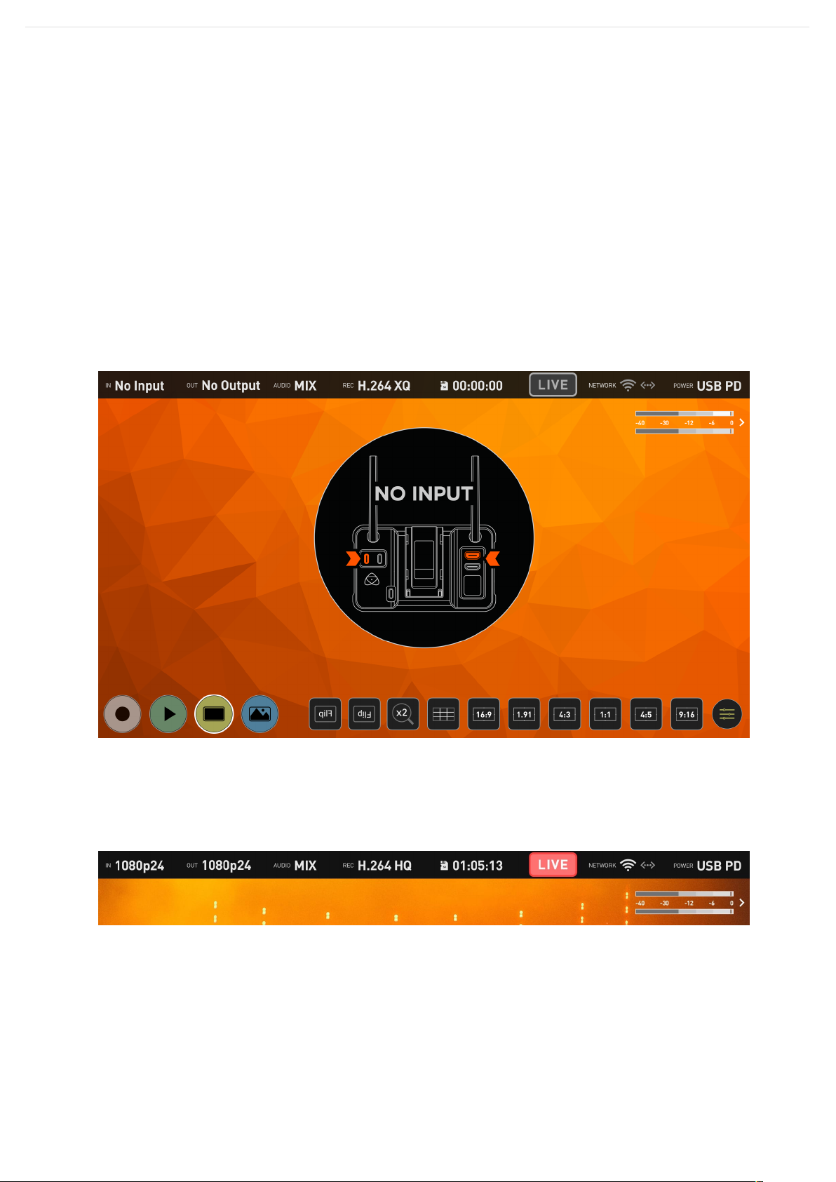
SD Card Icon: Shows a live preview of the remaining record time with the currently inserted
SD card.
LIVE Button: Press to start or stop the streaming output of the ZATO CONNECT.
Network: Details WiFi connection status and signal strength. The second icon highlights the
Ethernet connection status.
Power: Shows the Battery status based on a voltage reading or if the unit is powered via
USB PD instead.
Audio Meters: This shows the audio meters for the Output Mix.
Note: Pressing a label in the top bar acts as quick access that takes you to the
corresponding section in the AtomOS Lite menu system.
Bottom Row Menu:
The Bottom Row Menu provides quick access to a variety of the ZATO CONNECT's
functions.
Record Button: Press it to start or stop recording onto the inserted SD Card. This button
stays greyed out if no SD Card is inserted.
Note: It is also used to get back into Record/Live View mode if you've previously switched
over to Playback mode.
Play Button: Press to switch into Playback mode. Once in Playback mode, it is used to bring
up or hide the File Browser to select the clips you want to play back.
Monitor Button: Toggleable button to hide or show the Top Menu Bar and Bottom Row
Menu.
Overlay Button: Allows you to access the new Quick Access Bottom Function Row for
Overlays and PiP configuration.
Besides the four major function buttons, there are ten toggleable buttons for quick access to
the monitoring tools.
Horizontal Flip (Also known as Selfie Mode): Pressing this button flips the image horizontally
to make filming yourself more convenient.
Vertical Flip: Rotates the image by 180 degrees. Helpful if you want to use the ZATO upside
down.
x2 Zoom: Zooms into the image and allows users to check critical focus.
9 Grid: Used to make framing your shot following the rule-of-thirds more convenient.

16:9: Brings up the 16:9 Frame Guide.
1.91: Brings up the 1.91 Frame Guide.
4:3: Brings up the 4:3 Frame Guide.
1:1: Brings up the 1:1 (Square) Frame Guide.
4:5: Brings up the 4:5 Frame Guide.
9:16: Brings up the 9:16 Frame Guide.
Menu Icon: Provides quick access to the last Menu you've previously had open.

I/O TAB – INPUT, OUTPUT
& AUDIO
The I/O Tab in the ZATO CONNECT's main menu includes three sub-menus, which can be
accessed via the shelf menu on the left side of the menu window.
Input:
The Input menu includes the Video Input section on the left, allowing you to toggle between
HDMI and USB UVC video input sources.
To the right, under SIGNAL, the ZATO outlines the specifications of the input signal.
The signal specification consists of a short version of the resolution, the scan type, and the
frame rate.
Example: 1080p30
Resolution: 1080 (1920 x 1080)
Scan Type: p (Progressive)
Frame Rate: 30 (30 fps)
Compatible resolutions: 1080 (1920 x 1080) & 720 (1280 x 720)
Compatible Scan Types: p (Progressive)
Compatible Frame Rates: 23.98, 24, 25, 29.97, 30, 50, 59.94, 60
Output:
The Output menu details the output signal specifications of the ZATO CONNECT.

There is a row each for both HDMI and USB UVC outputs. Both have a dedicated SIGNAL
section that details the signal coming out of either port.
Note: "Video Output USB" is assigned to the USB-C port labeled USB 2 on the rear of the
device. Compared to USB 1, which just acts as a webcam input, it's a multipurpose port that
may also be used as a connection point for the included USB-C to Ethernet adapter.
Note: While the HDMI Out port supports outputting 1080p signals at up to 60fps, the USB
UVC output is limited to a maximum output frame rate of 30fps. If the ZATO CONNECT's
input signal surpasses 30fps, the ZATO's USB UVC output will automatically drop frames to
output a signal at half of the original frame rate.
Example: HDMI Input = 1080p60, HDMI Output = 1080p60, USB UVC Output = 1080p30
Audio:
The ZATO CONNECT comes equipped with a built-in Audio Mixer.
The mixer consists of 3 stereo audio meters. There is one for each audio input (Mic/Line,
HDMI, USB), as well as the fourth pair of stereo meters for the output mix.
To add an audio source to the mix, press the button below the corresponding meter.
Pressing the button again removes the source from the mix.
After adding a source, you can adjust the volume/gain via the slider to the right of each
meter to make sure that it's mixing well with the audio coming from the other channels.
Once the independent channel volumes have been adjusted to your liking, you may make
Input
Output
Audio
Network
Connect
Overlay
Record
Media
General
-12
-20°
MIC/LINE
»
Mic
-30*
-40.
Mic/Line
HDMI
USB
Output
Mix

final adjustments via the Output Mix slider.
Note: Both Line (-10 dBu) and Mic Levels (-40 dBu) are supported. You may switch between
them by pressing the label text on the right side of the menu window.

NETWORK TAB –!WIFI &
ETHERNET
In its factory state, the ZATO CONNECT isn't connected to the Internet. To connect your
ZATO to the web, which is required to use any of its CONNECT features like Streaming to
YouTube and Co., navigate to the Network tab in the main menu. In there, you'll find two
sub-menus: WiFi and Ethernet.
WiFi:
To connect your ZATO CONNECT to a WiFi network, either at home, your studio, your phone
hotspot, or any other WiFi access point, enable the WiFi switch on the left of this menu.
Within seconds, the ZATO will fetch a list of available networks within its range and display
them in the field on the right. If there are many WiFi networks nearby, use the scroll bar on
the right to navigate the list of entries.
Once you've found the WiFi network you want to connect to, double-tap the WiFi name to

open the network properties. In there, tap on the password field. A keyboard will pop up,
allowing you to enter the password.
Once you enter the password and confirm by pressing OK, the keyboard overlay closes, and
you'll return to the WiFi submenu. A loading indicator is displayed, highlighting that your
ZATO is attempting to connect to the WiFi network. If the connection is established
successfully, a green checkmark is displayed to confirm the connection status. If the
password you entered is incorrect, or if the connection can't be established, the ZATO
displays a warning message, asking you to try again.
If you double-tap the WiFi network you're currently connected to, you'll see a few new
options that weren't available in the unconnected state. On the left, there's the Auto Join
switch, allowing users to automatically join this WiFi network once it's in range. On the right,
there's a field displaying the ZATO's IP address.

At the bottom, there's the "Forget this Network" button that disconnects you from this
network immediately and also disengages the Auto Join functionality.
To turn offWiFi, press the switch on the left to disable it.
Ethernet:
Before establishing a network connection via Ethernet, ensure that"WiFi is disabled. Next,
connect the included USB-C to Ethernet dongle to the port labeled USB2 in the back of the
ZATO CONNECT.
After that, navigate to the Ethernet tab within the Network menu and press the ON/OFF
switch to put it from the OFF into the ON position.

Under Configure IPV4, you can either leave the ZATO in its default state, Using DHCP, or you
can switch it over to Manual mode for a fully manual network configuration.
Next, connect your Ethernet cable to the USB-C to Ethernet adapter. If you've selected
Using DHCP in the previous step, the ZATO will automatically fetch its network configuration
parameters from the Switch/Router you're connected to. In Manual mode, you need to enter
all these parameters manually, depending on your network configuration.
You can deactivate Ethernet via the ON/OFF switch on the right side of this menu.

CONNECT TAB –
!CONNECT TO ATOMOS
CLOUD STUDIO &
CONFIGURE STREAM
The Connect Menu allows you to pair your ZATO CONNECT with Atomos Cloud Studio. It
also displays the network connection status and the status of the connection to the Atomos
Cloud.
Note: Before connecting to the Atomos Cloud, your device must first be connected to the
Internet. You can connect your ZATO CONNECT to the Internet via WiFi, or via the included
USB-C to Ethernet adapter. For more information, check out the article "Network Tab –!WiFi
& Ethernet".
Once the ZATO CONNECT is connected to the internet, the status of the Connect menu
changes to reflect the connection status.

and its details. The three word code is displayed on the image of the device and the device
type appears. When your device is connected to Atomos Cloud, a green circle will appear
next to the device nickname at the top of the device box.
The Connect Menu page of your ZATO CONNECT will also update, with another green circle
indicating that you're connected to the Atomos Cloud. The current mode will also be
displayed under Device Mode, with Device Id used for pairing right next to it.
Note: Since the destination and stream key have not been configured yet, these fields will
stay empty for now.
Next, you will need to configure the services for this device at atomos.cloud. Tap on the +
symbol next to Add Destination in the device box and a new window will open, displaying
the destination options.

Press "Pair Device". The ZATO CONNECT now communicates with Atomos Cloud Studio
and is assigned a unique three-word-combination, which is displayed in the Connect menu
along with a!QR code.
Scan the QR code to connect to Atomos Cloud Studio on your mobile device, or navigate to
atomos.cloud on a desktop browser. Either sign up for a new account, or log in to an
existing account. Once logged in, press the "Pair Device" button and enter the three words
from the ZATO CONNECT's Connect menu. After entering the words, give your device a
nickname.
After going through the initial setup steps, the ZATO CONNECT will be paired with your
Atomos Cloud account. The Devices tab updates to show an image of the device you paired
Other manuals for ZATO CONNECT
1
Table of contents
Other Atomos Measuring Instrument manuals
Popular Measuring Instrument manuals by other brands

Endress+Hauser
Endress+Hauser Liquicap T FMI21 technical information

Simpson
Simpson 2865 instruction manual

Teledyne
Teledyne T100 instruction manual

KBR
KBR multisio D6-ESBS-4RO-ISO-1 user manual

Ahlborn
Ahlborn ALMEMO 202-S operating instructions

Flexim
Flexim FLUXUS ADM 5 07 Series Supplement to User’s Manual