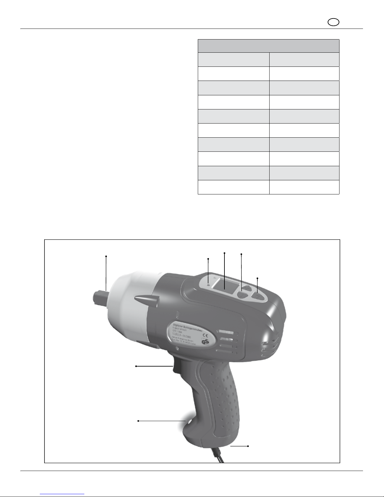
The digital electrical impact wrench
You’ll soon have the hang of it with the electrical impact
wrench. Its simple and clear menu navigation enables you to
easily handle the appliance. In addition to the quiet running
of the appliance, the premium electrical impact wrench also
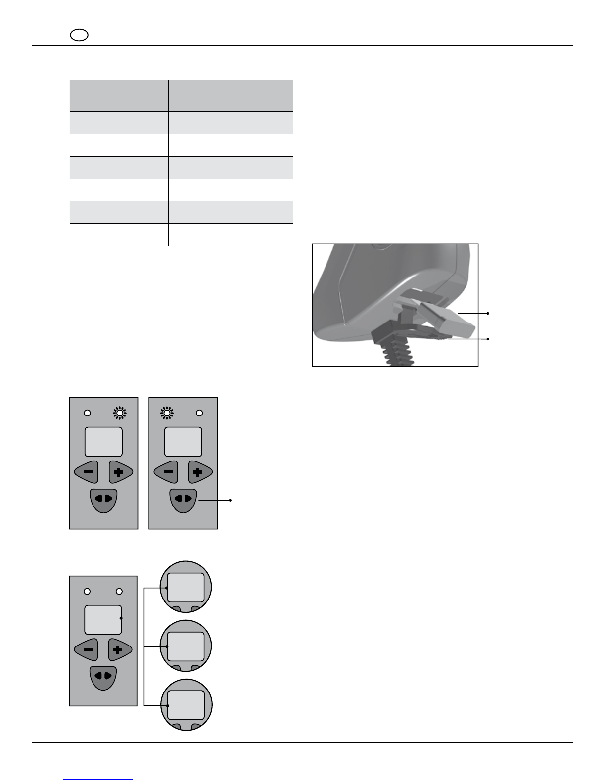
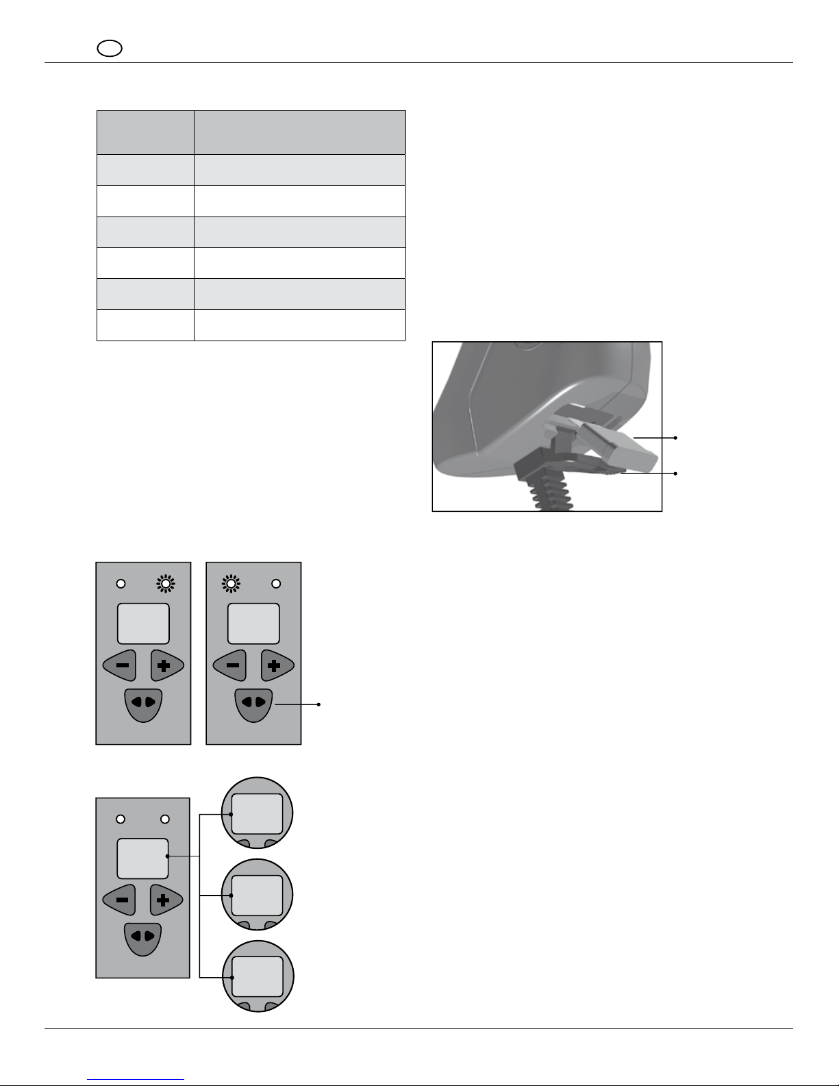
offers the user further features. For example, there are 3 dif-
ferent Newton metre settings to select (see Figure 3): Steel,
aluminium or an individual setting (up to 240 Nm). Due to the
rubber handle and its ergonomic design, the electrical impact
wrench sits perfectly in the hand and thanks to its working
lamp, you will even be able to work in poor light conditions
in the future.
Area of application
The electrical impact wrench is designed for the tightening
and loosening of screw fastenings. The required power vol-
tage for the appliance is 12 V / 10 A nominal. In order to
prevent damage to people or equipment, please familiarise
yourself with the functions of this appliance before using it
for the first time. In order to do this, please read the following
operating instructions and safety information.
Only use the appliance as described and only use the appli-
ance in the areas of application that are stated. Always observe
the following operating information and retain the operating
instructions for later use. In the event that the appliance is
given to a third party, please ensure that all documentation
is also passed on.
Safety information
ATTENTION: When using the electrical impact wrench, the
following safety measures against electric shocks as well as
fire and injury risks must be observed. Please read this infor-
mation and the following operating instructions before using
the appliance for the first time and safely retain the informa-
tion.
Never expose the 12 V electrical impact wrench to rain or wa-
ter. Do not use the appliance in moist or wet conditions and
keep it away from ammable liquids and gases.
1. Be protected against an electric shock.
2. Avoid any bodily contact with earthed parts, for example:
Heating pipes or radiators, ovens or refrigerators, etc.
3. Keep the appliance and cable away from children and
keep other people away from your working area.
4. Keep the electrical impact wrench in the transport case
and out of reach of children in a dry, elevated / locked
location.
5. Please do not use the electrical impact wrench for purpo-
ses for which it is not intended and do not overload the
appliance.
6. Always wear appropriate work clothing whilst using the
appliance and ensure that no loose clothing, hairs or je-
wellery can be gathered by rotating parts of the appliance.
When working outdoors, please ensure that sturdy shoes
are worn and that rubber gloves are worn wherever possi-
ble when using the appliance.
7. Please only use the cable for purposes for which it is in-
tended and never carry the electrical impact wrench by the
cable. Please do not pull on the cable in order to discon-
nect the appliance from the cigarette lighter. Protect the
cable against oil, heat and sharp edges.
8. Please use clamping devices / bench vice in order to
secure the components in order to keep both hands free
for the operation of the electrical impact wrench.
9. Ensure that you are always balanced when working with
the appliance and ensure that a secure standing position
is taken.
10. Always keep the electrical impact wrench clean and take
care of the appliance in order to be able to work better and
in a safer manner. Observe the maintenance guidelines
and information regarding the replacement of screws. Be-
fore each usage, inspect the power cable of the electrical
impact wrench. In the event of damage, only allow a re-
cognised specialist repair or replace the part in question.
Please keep the handle dry and free of grease or oil at
all times.
11. Remove the plug from the cigarette lighter before underta-
king maintenance work or replacing the tools of the elec-
trical impact wrench.
12. The electrical impact wrench may not be connected to the
mains whilst travelling.
13. Before switching the appliance on, please ensure that
tool keys or adjustment tools have been removed from
the appliance.
14. Never carry an electrical impact wrench that is connected
to the mains with your finger pressed on the switch and
ensure that work is carried out in a rational and concen-
trated manner.
15. Always inspect the electrical impact wrench and its moving
parts for possible damage and immaculate functioning.
16. Ensure that all parts are correctly assembled in order to
guarantee trouble-free operation of the appliance.
17. Damaged parts may only be repaired by a recognised
electrical specialist repair shop / importer or may only be
repaired via replacement with original replacement parts.
18. ATTENTION: Only use accessories are auxiliary devices
that are contained in the delivery contents.
19. ATTENTION: Always inspect the torque of the tightened
screws by using the appropriate tool and inspect safety-