ATS RTFO User manual

MAN - RTFO - REV: Org
RTFO
Rolling Thin Film Oven
This manual contains important operating and safety information. Carefully read and
understand the contents of this manual prior to the operation of this equipment.
www.atspa.com
INSTRUCTION MANUAL

MAN - RTFO - REV: Org
REVISED SEPTEMBER 2019
Information in this document is subject to change without notice and does not represent a commitment on the part of
Applied Test Systems (ATS)
154 East Brook Lane
Butler, PA 16002
USA
Telephone: +1-724-283-1212
For assistance with set-up or operation, contact the ATS service department. Please have this manual and product
serial number available when you call.
© Copyright Applied Test Systems 2019

i
MAN - RTFO - REV: Org
Manual Contents
A. Introduction...................................................................................................................................1
A.1 Unpacking ............................................................................................................................................................1
A.2 Warranty Information...........................................................................................................................................1
A.3 After Sale Support ...............................................................................................................................................1
B. Safety.............................................................................................................................................2
B.1 For Owners, Operators, and Maintenance...........................................................................................................2
B.2 Warnings..............................................................................................................................................................3
B.3 Cautions................................................................................................................................................................4
C. System Overview..........................................................................................................................5
C.1 General Description .............................................................................................................................................5
Product Specications...................................................................................................................................5
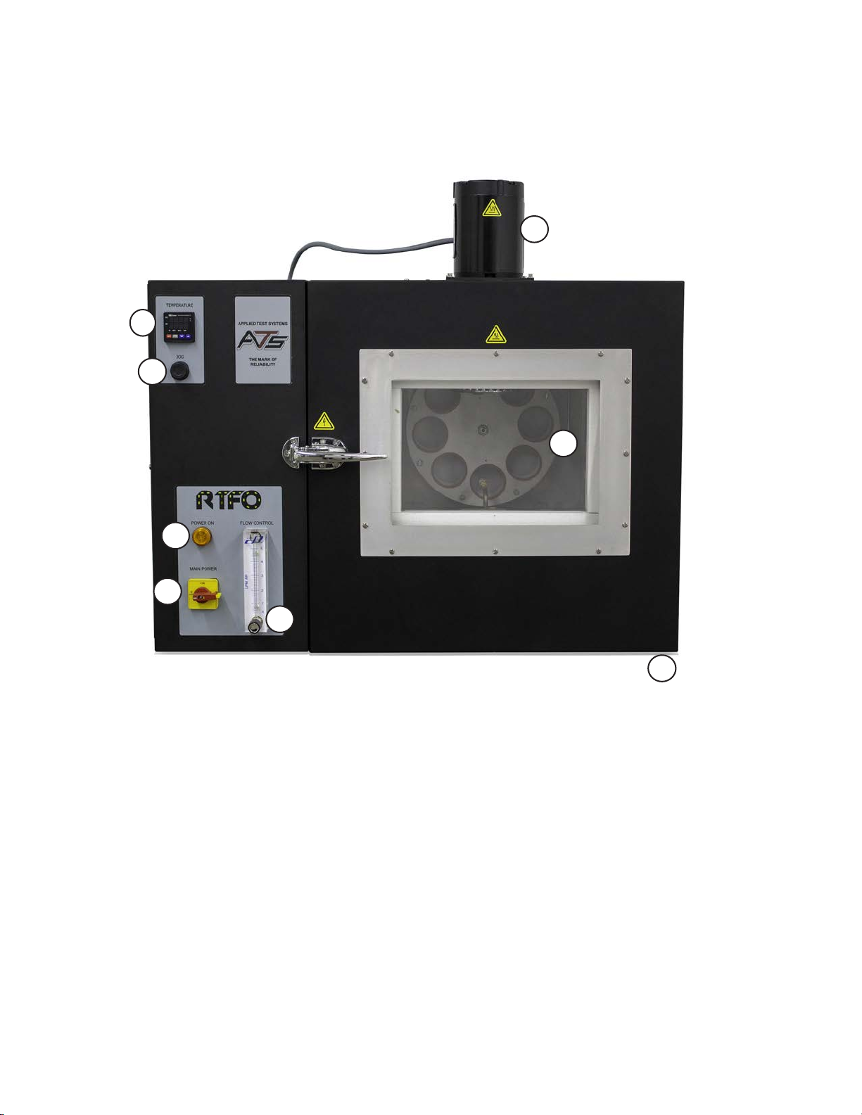
C.2 RTFO Layout........................................................................................................................................................6
RTFO Front.................................................................................................................................................... 6
RTFO Back.................................................................................................................................................... 7
RTFO Chamber............................................................................................................................................. 8
Panel Layout and Components.....................................................................................................................9
Temperature Controller ............................................................................................................................... 10
D. Installation...................................................................................................................................11
D.1 General Installation.............................................................................................................................................11
D.2 Adjusting the Air Flow.........................................................................................................................................11
D.3 Setting the Temperature .....................................................................................................................................12
D.4 Leveling the Machine..........................................................................................................................................13
E. Verication ..................................................................................................................................14
E.1 Temperature Verication .................................................................................................................................... 14
E.2 Verication of Air Flow ........................................................................................................................................14
F. Operation .....................................................................................................................................15
F.1 Basic Operation .................................................................................................................................................. 15
G. Troubleshooting .........................................................................................................................16

ii MAN - RTFO - REV: Org
G.1 Preface............................................................................................................................................................... 16
G.2 Unit Will Not Turn On..........................................................................................................................................16
G.3 Carousel Will Not Rotate....................................................................................................................................17
G.4 Fan Motor Will Not Rotate ..................................................................................................................................18
G.5 Unit Has No Airow ............................................................................................................................................18
G.6 Unit Will Not Heat ...............................................................................................................................................19
H. Maintenance................................................................................................................................20
H.1 Cleaning the Unit................................................................................................................................................20
H.2 Replacing Damaged Cables...............................................................................................................................20
H.3 Bearing Service and Replacement.....................................................................................................................20
H.4 Chain Maintenance.............................................................................................................................................22
H.5 Tray Cleaning.....................................................................................................................................................22
H.6 Replacement Parts and Accessories .................................................................................................................23
Appendix A: Warranty ....................................................................................................................25
Appendix B: Wiring Diagram .........................................................................................................26
Appendix C: Image Glossary.........................................................................................................30

MAN - RTFO - REV: Org | A. Introduction 1
A. Introduction
A.1 Unpacking
Retain all cartons and packing materials until the unit is operated and found to be in good condition. If damage has
occurred during shipping, notify Applied Test Systems (ATS) and the carrier immediately. If it is necessary to le a
damage claim, retain the packing materials for inspection by the carrier.
WARNING: Always lift from under the oven with forks or proper lifting equipment. Do not lift from
the electrical enclosure.
A.2 Warranty Information
All new ATS systems are shipped with a warranty. Units have a warranty against defective parts and workmanship for
one full year from the date of shipment. Please see APPENDIX A of this manual for complete details on the warranty.
A.3 After Sale Support
If there are any questions concerning the operation of the unit or software, contact the ATS Service Department at
+1-724-283-1212.
Before calling, please obtain the software revision number and the serial number from the unit’s data tag. A sample
data tag is illustrated below, and can be completed with the unit’s information for easy reference. Please be prepared
to give a complete description of the problem to the ATS Service Department at +1-724-283-1212.
Figure A.1: ATS Sample Data Tag

MAN - RTFO - REV: Org | B. Safety2
B. Safety
B.1 For Owners, Operators, and Maintenance
Read and understand all instructions and safety precautions listed in this manual before installing or operating the
unit. If there are any questions regarding operation of the unit or the instructions in this manual, contact the ATS
service department at +1-724-283-1212.
In addition to the safety warnings listed on the equipment, warnings are posted throughout this manual. Read and
follow these important instructions. Failure to observe these instructions can result in permanent damage to the unit,
signicant property damage, personal injury, or death.
All Applied Test Systems (ATS) equipment is designed to be operated with the highest level of safety. To maintain the
safe operation of this tester, ATS endeavors to educate the operator about safety issues surrounding certain parts of
the machinery. These safety issues are addressed through the use of labeling on the equipment. The following labels
may appear on your test unit:
Burn Hazard/Hot Surface
Electrical Shock/Electrocution
Protective Earth (Ground)
General Danger. When this symbol is displayed, user must always consult the manual to
determine the potential hazard(s) and any actions required to avoid them.
No Access for Unauthorized Persons
Read Operator’s Manual
Hand Entanglement
Ignition/Explosion
Additionally, the responsible body shall ensure that:
i. appropriate decontamination is carried out if hazardous material is spilled onto or into the
equipment.

ii. no decontamination or cleaning agents are used which could cause a hazard as the result of a
reaction with parts of the equipment or with material contained in it.
iii. the manufacturer or his agent is consulted if there is any doubt about the compatibility of
decontamination or cleaning agents with parts of the equipment or with the material contained in it.
B.2 Warnings
The following statements are warning statements. Unlike caution statements, warning statements alert the operator
to conditions that may injure personnel. Operators must be aware of these conditions in order to prevent injuries that
may occur while operating this equipment.
WARNING: Disconnect power prior to performing maintenance. Place Main Power Switch
in “OFF” position and disconnect the line cord from the power source before performing any
maintenance procedures.
WARNING: Obey electrical code requirements. The oven and control system must be wired and
grounded in accordance with national and electrical code requirements.
WARNING: Be careful when working with equipment at elevated temperatures. In order to prevent
burns, wear protective clothing.
WARNING: Use caution when opening the oven. Electrically heated equipment can cause severe
burns.
WARNING: The air circulation fan is controlled by a door switch to protect operators from the fan.
If the fan continues to operate after the door is opened, discontinue use immediately and contact
the ATS Service Department at +1-724-283-1212.
WARNING: Unpack and operate on a stable surface.
WARNING: Pinch hazard.
WARNING: Do not open the side panel unless explicitly instructed to do so for troubleshooting
purposes.
WARNING: Do not use ammable solvents to clean the oven or use with products other than
designed for.
MAN - RTFO - REV: Org | B. Safety 3

WARNING: Using solvents or products not specied by the equipment manufacturer may create
potential for formation of ammable or volatile gas mixtures. Always refer to product SDS or
contact the manufactuerer.
WARNING: Do not place objects that may obstruct the sample rack or blower.
WARNING: Before removing the air coil assembly always make sure the unit is powered off and
unplugged.
WARNING: Unit should always be operated in a well ventilated area. Refer to and adhere to SDS
sheets of product being tested.
WARNING: Proper Personal Protective Equipment (PPE) required for removal of hot glassware.
B.3 Cautions
The following statements are caution statements. These statements alert the operator to conditions that may damage
equipment. Operators must be aware of these conditions in order to ensure safe operation of the equipment.
CAUTION: Installation of electrical devices must be accomplished by competent personnel and
done in accordance with any current local and national codes.
CAUTION: The RTFO must be grounded and wired in accordance with national and local
electrical code requirements.
CAUTION: Before energizing the electrical power to the RTFO, place all controls in an OFF
position.
CAUTION: Do not exceed the maximum operating temperature.
CAUTION: All supporting and contacting surfaces must be non-ammable. Do not allow
ammable materials to contact the shell.
CAUTION: If an emergency shutdown needs to be performed, place ON/OFF switch in an OFF
position.
CAUTION: Do not overow RTFO bottles. Refer to test specications for proper amount of
material.
MAN - RTFO - REV: Org | B. Safety4

MAN - RTFO - REV: Org | C. System Overview 5
C. System Overview
C.1 General Description
The RTFO provides a controlled ow of heated air directed into the openings of horizontal glass bottles as they
rotate on a carousel rack, simulating short term aging of binder during production, handling, and paving operations. It
exceeds ASTM D2872, AASHTO T 240, and California 346 testing standards with a 5 to 8 minute recovery time.
When operating the RTFO, always make sure to wear the proper personal protective equipment (PPE), including high
temperature work gloves.
This equipment is intended to be used only as described in this manual and the applicable standards. Use in any
other manner may result in personal injury, property damage, damage to the equipment, and void of warranty.
Product Specications
Size 34.50” W x 24” D x 32.00” H
Power Requirements 208V-240V, 1 ph, 50/60 HZ, 10A
Power Rating 2400 VA (+/- 10%: 2640 VA - 2160 VA)
Air Pressure 60-150 PSI inlet pressure
Weight 270 lbs.
Temperature Range 0⁰C to 200⁰C ± 0.5⁰C
Specimen Capacity 8 high temperature glass bottles

MAN - RTFO - REV: Org | C. System Overview6
C.2 RTFO Layout
Front of Unit
1. Temperature Controller
2. Fan Motor
3. Carousel Jog Button
4. Power Indicator
5. Power Switch
6. Flow Meter
7. Carousel with High Temp. Silicone
Rings
8. Leveling Legs
Figure C.1: RTFO Front
1
2
3
4
5
6
7
8

MAN - RTFO - REV: Org | C. System Overview 7
Back of Unit
1. Cooling Fan
2. Air Inlet/Input Filter
3. Power Inlet Module
Figure C.2: RTFO Back
1
2
3

MAN - RTFO - REV: Org | C. System Overview8
Interior Chamber
1. Internal RTD
2. Fan
3. Carousel
4. Jar Holder
5. Air Oriface
6. Airline Plumbing
7. Tray
8. Heaters (located under tray)
Figure C.3: RTFO Chamber
1
2
3
4
5
67
8

MAN - RTFO - REV: Org | C. System Overview 9
Panel Layout and Components
*Fuses 1 & 2 for 24VDC Supply
**Fuse 3 for Blower
***Fuse 4 for Sample Rack
1. Fuses 1-2*
2. Fuse 3**
3. Fuse 4**
4. Blower Drive
5. Sample Rack Drive
6. Heat Control
7. Air Regulator - setting should be at
22-25 PSI
8. Line Filter
9. Circuit Breaker
10. Sample Rack Motor
Figure C.4: Panel Layout & Components
1
2 3
4 5
67
88
9
10

MAN - RTFO - REV: Org | C. System Overview10
1. PV Display
2. SV Display
3. Set Button
4. °F, °C LEDS
5. Down Button
6. Up Button
Figure C.5: Temperature Controller
1
2
3
4
5 6
Temperature Controller
PROCESS VALUE (PV) DISPLAY: The Process Value Display indicates the value from the input source. This is the
actual oven temperature, shown in red, from the thermocouple.
SET VALUE (SV) DISPLAY: The Set Value Display indicates the desired set point in green.
SET BUTTON: Press the SET button to select the desired function mode and conrm the setting value.
ROTATE BUTTON: Press the ROTATE button to select parameters within the function mode.
DOWN BUTTON: Press the DOWN button to decrease values displayed on the SV display. Hold down this button to
speed up the decrement.
UP BUTTON: Press the UP button to increase the values displayed on the SV display. Hold down this button to
speed up the increment.

MAN - RTFO - REV: Org | D. Installation 11
D. Installation
D.1 General Installation
The following procedure describes how to properly unpack, connect, and power the RTFO.
1. Carefully remove the RTFO from shipping packaging, removing any packing material and/or accessories that may
have been placed inside of the oven chamber for shipment.
WARNING: Obey electrical code requirements. To avoid electric shock, the oven and
control system must be wired and grounded in accordance with national and electrical code
requirements. Use a properly grounded electrical supply of correct voltage and current handling
capacity.
2. The oven has been completely tested and checked at ATS before shipment. A power cord 10 feet long is supplied
with the oven. The end user is required to supply a plug and receptacle rated for 10 Amp, 240 Volt, single phase,
electrical service. The customer supplied plug shall be installed by a qualied electrician in accordance with the
Electrical Wiring Diagram (Appendix B) and all applicable Electric and Safety Codes.
3. Rotate the power switch on the front from the horizontal OFF position to
the vertical ON position (Fig. D.1 and Fig. D.2) to turn the unit on. The power
light above the switch should now be illuminated.
4. This unit requires an air supply of at least 60-150 PSI.
5. Set up the air by installing your male air tting into the female receiver (¼”
NPT) (Fig. D.3). Seal threads with Teon tape.
D.2 Adjusting the Air Flow
The RTFO’s airow should always be set at the specication provided on
the calibration label attached to the side of the airow meter (Fig. D.4). If this Figure D.3: Air Receiver
Figure D.1 - Power switch in the OFF position Figure D.2 - Power switch in the ON position

MAN - RTFO - REV: Org | D. Installation12
setting is not correct, adjust the airow to match the value on the label. Adjustments are accomplished by rotating the
knob located on the bottom of the gage (Fig. D.5).
D.3 Setting the Temperature
1. To change the RTFO temperature set point, press and hold the UP and DOWN arrow buttons at the same time
until the GREEN SV temperature display begins to blink.
2. Hold the UP arrow button to increase temperature or the DOWN arrow button to decrease temperature until the
desired set point is reached.
3. When the desired temperature set point is reached, press the red SET button (Fig. D.6).
Figure D.4 - Calibrated label
location on airow meter
Figure D.5 - Airow meter
Figure D.6 - Temperature Controller

MAN - RTFO - REV: Org | D. Installation 13
D.4 Leveling the Machine
1. Using a digital level check the level on the top of the RTFO and the bottom portion of the RTFO for a reference
point.
2. Insert the leveling jar into the carriage to check the level at different points of rotation. The level should be +/- 1.0
degrees from the reference point.
3. Use the adjustable legs on the bottom of the RTFO to attain proper level.

MAN - RTFO - REV: Org | E. Verication14
E. Verication
E.1 Temperature Verication
1. Insert a temperature proble into the top left port-hole.
2. Connect probe with a brass block to the RTD inside (right side).
3. Allow oven to preheat.
4. Allow unit to heat up and stabilize.
5. Once stabilized at the temperature that needs verifying, take ve readings 10 minutes apart and compare results.
E.2 Verication of Air Flow
1. Attach a ow verication device to the copper tubing inside the RTFO (Sec. C.2, Fig. C.3) (if using a ow through
device the orice can be removed from the tubing and attached to the downstream end).
2. Allow 15 minutes to stabilize.
3. Take 5 comparison readings every 3-5 minutes. 3 readings minimum, 5 recommended.

MAN - RTFO - REV: Org | F. Operation 15
F. Operation
F.1 Basic Operation
WARNING: The RTFO door and glass will be very hot during operation. Use personal protective
gear when operating the RTFO and handling materials associated with the testing procedure.
1. Turn the power switch on the front of the Rolling Thin Film Oven (RTFO) to the ON position. The POWER light
located on the front of your RTFO will light up and the temperature controller display will power on.
2. Use the temperature controller to set the RTFO temperature to the desired specication. See (Sec. D.3) for details.
3. Verify that the air ow setting matches the value on the side of the meter. Adjust if necessary. See (Sec. D.2) for
details.
4. Once the chamber reaches the set point and has stabilized per the specication, load the sample jars. Rotate the
carousel using the JOG button. It is normal for the unit temperature to drop when the door is open. The RTFO will
recover back to set point within eight minutes once the unit door is closed.
5. Once the aging process is complete, open the door and remove the samples per the specication.

MAN - RTFO - REV: Org | G. Troubleshooting16
G. Troubleshooting
G.1 Preface
Listed within this section are the most common troubleshooting errors that operators may encounter when using the
RTFO. Users may follow the steps provided to work through these basic errors.
WARNING: Any additional issues or system errors should be brought to the attention of the ATS
Service Department immediately. Please do not attempt to independently x any other system
errors. Any additional errors xed independent of technical support at Company could result in
damage to the equipment, or injury on the part of the operator.
WARNING: Place Main Power Switch in “OFF” position and disconnect power before removing
side cover to access electrical panel. ONLY open the side panel when explicitly instructed to.
Do not touch or alter anything within the side panel unless instructed to. Failure to adhere to this
warning could result in severe electrical shock, injury, or death.
G.2 Unit Will Not Turn On
1. Verify the system is plugged in to the correct power source and that the cord is secured to the power input on the
machine.
2. Verify the power switch on the front of the unit is in the ON position and the amber light is on (Sec. D.1, Fig. D.2).
3. Verify that the system’s circuit breaker is not tripped. Remove the side door panel and refer to (Sec. C.2, Fig. C.4)
for the circuit breaker location. If the breaker is in the OFF position instead of the ON position (Fig. G.1), switch it
back to the ON position (Fig. G.2).
Figure G.1: Circuit breaker in the
OFF position Figure G.2: Circuit breaker in the
ON position
Table of contents
Other ATS Oven manuals
Popular Oven manuals by other brands

Electrolux
Electrolux EOB7S31V user manual

Electro Depot
Electro Depot MO 46MF KX 225C Instructions for use

Candy
Candy FCNES825XL WIFI User instructions

Smeg
Smeg SA112-8 specification

AEG
AEG COMPETENCE B4401-4 operating instructions

Middleby Marshall
Middleby Marshall PS314SBI Owner's operating and installation manual