attitude industries Electronic Jet Kit User manual

Rev 1.1.0 Attitude Industries PN 85004 Patent Number: 7,000,599
Attitude Industries Phone: 406-539-3015 Email: support@tunewithattitude.com
BOX 582 Spanish Fork, UT 84660 Website: www.tunewithattitude.com
Electronic Jet Kit
Instructions
I
In
ns
st
ta
al
ll
la
at
ti
io
on
n
This is about a 20-minute install time.
Tools required: Basic wrench set
Thank you for choosing the Attitude Jet Kit for your Polaris Snowmobile
Our technology interfaces with your fuel injected vehicle to allow EFI tuning based on carburetor tuning
logic. Our product gives you the equivalent of enriching the pilot jet and mixture screw (green mode),
raising the needle (yellow mode), and installing a larger main jet (red mode).
Due to the wide variety of applications we try to be very generic with our instructions, so if you need
further assistance with an install call technical support at 1-406-539-3015, 1-801-794-9367 or see our web
site at www.tunewithattitude.com.
This product is capable of handling the fuel needs for a turbo application up to 18 lbs of boost with a rising
rate fuel reg. If you see a need for a different fuel curve please contact Attitude Industries.
This is an Electronic Jet Kit. Like jet kits in the past the more you modify, the more responsibility you take
in getting your fuel curve right. In the event you fail to create a better tune-up, we suggest looking to our
website at www.tunewithattitude.com for some base settings and tuning help.
Some vehicle modifications with Attitude Industries products may NOT be permitted for use on public
roads and in some cases may be restricted to closed course competition. Those products NOT identified as
US EPA legal are intended for off road or marine applications only. Products are NOT intended for use on
emission controlled vehicles.

Attitude Industries Phone: 406-539-3015 Email: support@tunewithattitude.com
BOX 582 Spanish Fork, UT 84660 Website: www.tunewithattitude.com
Electronic Jet Kit
Instructions
Installation
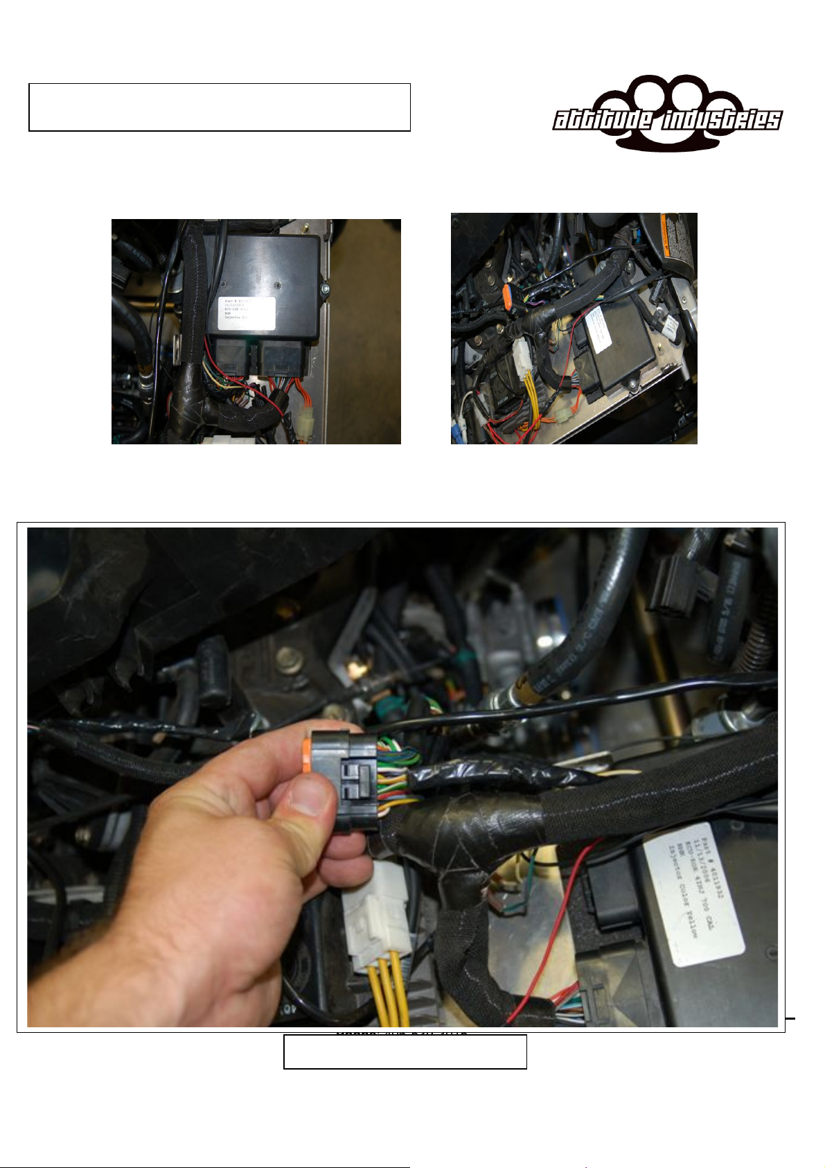
1. Remove LH side panel and black cover over the clutch guard to gain access to the ECU. (see figure 1)
2. Then remove the ECU plug that is located closer the engine or center of sled (see figure 2)
3. When you unplug the ECU connector you will flip it over and see a Yellow wire with a white stripe and a
Green wire with a white strip shown in figure 3.
4. You will cut back some the wire insulator to gain access to more of the wiring harness.
5. Next cut the yellow wire with the white stripe in leaving room to splice into the harness.
6. Splice in the Attitude Box starting with the solid yellow wire. Splice it in to the wire close to the ECU
plug. Than spice the white with yellow stripe to the other end of the wire leading to the wiring harness.
(see figure 4 for wiring diagram)
7. Splice the Attitude box Grey wire into the factory Green wire with a white stripe close the ECU plug.
Than splice the green with grey stripe to the other wire end of the wire leading towards the harness.
8. Place the black wire on the TFI box to a ground on the snowmobile Chassis.
9. In the same loom as the Green/white and yellow/white locate the red wire with blue tracer. Use the
supplied T-tap and spade connector and connect the red wire from the Attitude box. This is your12 volt
power source for the attitude box.
10. Next locate the air temp sensor in the factory box. Cute and splice into the factory blue wire. The tan wire
from the attitude box towards the air temp sensor with the pink yellow splicing into the other end towards
the harness. ( see figure 5)
11. Connect the Boost tube from the box the air box to read boost pressure.
12. The white wire on the box is not used on this application.
13. Find a good mounting location for the box. Try to find a spot away from excessive heat and moisture. (see
figure 5)
14. Start the snowmobile
15. You should have scrolling green lights, followed by a blinking green on light #1 and red on #8. When you
take the snowmobile to a high idle you should have a solid green light on #1. This ensures all connection
is good
Trouble Shooting
If you do not see the LED lights scroll or go to a solid green light please check all connections.
If the motor seems
to run on one cylinder please call are tech lines or e-mail us. Some basic things to check for are the following.
1. Check your ground wire to insure that you have a good ground.
2. Check all connections and make sure that pins are properly seated and making good contact.
3. Make sure no wires have come loose, or been rubbed threw.
If all the above seems ok please contact us at 1-406-539-3015 or e-mail us at
Attitude Industries Phone: 406-539-3015 Email: support@tunewithattitude.com
BOX 582 Spanish Fork, UT 84660 Website: www.tunewithattitude.com
Electronic Jet Kit
Instructions
Figure 1 Figure 2
Polaris
Figure 3

Attitude Industries Phone: 406-539-3015 Email: support@tunewithattitude.com
BOX 582 Spanish Fork, UT 84660 Website: www.tunewithattitude.com
Electronic Jet Kit
Instructions
Figure 5 Figure 6
Figure 4

Attitude Industries Phone: 406-539-3015 Email: support@tunewithattitude.com
BOX 582 Spanish Fork, UT 84660 Website: www.tunewithattitude.com
Electronic Jet Kit
Instructions
T
Tu
un
ni
in
ng
g
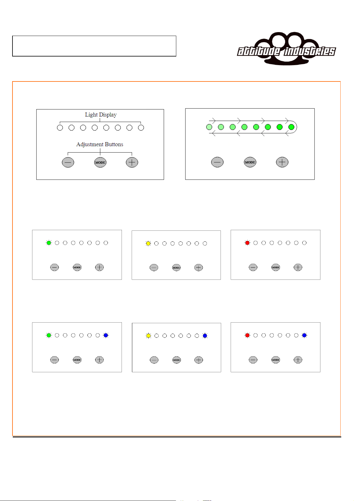
1. Start the vehicle. If installed correctly the unit will begin its startup sequence where the LED’s
display a single green light scrolling back and forth for a couple of seconds. After the startup
sequence a single green light should be displayed on the very left LED. With an improper
installation the light display will consist of a flashing green light to the left and a flashing red
light to the right. If this occurs then the unit is not receiving a proper injector signal. Recheck the
wire connections for any defects. (The flashing green and flashing red lights is common for a proper
installation during deceleration because the stock fuel map shuts off the fuel injectors during this
process.)
2. At this point you are ready to adjust the unit to the base settings supplied with the unit. The first
thing to do is ensure the proper code was supplied by checking the six programmable features
are available. To begin the process, press the MODE button. To enter each successive mode, just
press the MODE button again.
3. Description of each mode and light representation:
Mode 1 - Green - Cruise fuel adjustment
Similar to adjusting pilot jet and mixture screw on carburetor vehicles. Decreasing the light
value will add a lower amount of fuel. Increasing light value will add more fuel.
Mode 2 - Yellow - Acceleration fuel adjustment
Similar to raising or lowering the needle on carburetor vehicles. Decreasing the light value
will add a lower amount of fuel. Increasing light value will add more fuel.
Mode 3 - Red - Full Throttle fuel adjustment
Similar to adjusting the main jet on carburetor vehicles. Decreasing the light value will add
a lower amount of fuel. Increasing light value will add more fuel.
Mode 4 - Green/Blue – Fuel per pounds of Boost
This is your main adjustment for your turbo and is 90% of your tunning. Use this setting to
add fuel to get your sled running its desired A/F or EGT
Mode 5 - Yellow/Blue – Acceleration RPM switch
This fuction is the RPM switch point for the acceleration mode. This is for different turbo s
and different VES springs. Box is preset to normal level. The Lower the number the
Sooner accel fuel is added. Higher the number the later.
Mode 6 - Red/Blue – Full Throttle RPM switch point adjustment
This function is the RPM switch point for when the full throttle fuel addition engages.
Adjustment is necessary to mostly match different pipes or big bore kits which require
different fueling needs. Decreasing the light value will cause the full throttle fuel to engage
at a lower RPM. Increasing the light value will increase the RPM it engages.
Attitude Industries Phone: 406-539-3015 Email: support@tunewithattitude.com
BOX 582 Spanish Fork, UT 84660 Website: www.tunewithattitude.com
Electronic Jet Kit
Instructions
General Layout Start-Up Light Sequence
Mode 1 – Green Mode 2 – Yellow Mode 3 – Red
Mode 4 – Green / Blue Mode 5 – Yellow / Blue Mode 6 – Red / Blue

Attitude Industries Phone: 406-539-3015 Email: support@tunewithattitude.com
BOX 582 Spanish Fork, UT 84660 Website: www.tunewithattitude.com
Electronic Jet Kit
Instructions
Tuning Tips
1. Use the Green to adjust your cruise circuit. If you see a rich idle you need to adjust your fuel pressure. Please
contact the vendor of your turbo kit for their base fuel pressure setting they recommend or contact attitude
industries for what we recommend.
2. The Yellow light will always be equal to or less then your green light.
3. Use the Green Blue setting to dial in your desired A/F mixture or EGT. Use this setting as much as possible
and then use the red for fine tuning. This will allow your sled to move with elevation and temp better.
4. If your sled seems to come out of tune when changing in elevation or temp shut your snowmobile OFF and
then restart it. This will allow the Attitude box to zero its self and recalibrate our boost sensor. Do this before
adjusting your Attitude Box.

Attitude Industries Phone: 406-539-3015 Email: support@tunewithattitude.com
BOX 582 Spanish Fork, UT 84660 Website: www.tunewithattitude.com
Electronic Jet Kit
Instructions

Attitude Industries Phone: 406-539-3015 Email: support@tunewithattitude.com
BOX 582 Spanish Fork, UT 84660 Website: www.tunewithattitude.com
Electronic Jet Kit
Instructions
Table of contents
Popular Automobile Accessories manuals by other brands


Fab Fours
Fab Fours Vengeance V4051 installation instructions

Thule
Thule 168 user manual

Buyers
Buyers 1501250 installation instructions

OMNISTOR
OMNISTOR OMNIBIKE ELITE instructions

APS Auto Parts Specialist
APS Auto Parts Specialist IA04SIA2B installation instructions

Cycle Country
Cycle Country ATV PLOW MOUNT Assembly & owners manual


