ATX Maxnet II QMP 1000 User manual

QMP1000 Forward RF Amplier
Installation & Operation Manual
CCAP™
Com
pliant
1.2 GHz

MAXNET®II is a registered trademark of ATX in the United States and/or other countries. Products or features contained herein may be covered by one or more U.S. or foreign
patents. Other non-ATX product and company names in this manual are the property of their respective companies.
Although every effort has been taken to ensure the accuracy of this document it may be necessary, without notice, to make amendments or correct omissions.
Specications subject to change without notice.

TABLE OF CONTENTS
Page
1. PRODUCT DESCRIPTION........................................................................................................................ 1-1
1.1. Functional Diagrams.......................................................................................................................... 1-2
1.2. Technical Specications .................................................................................................................... 1-3
2. INSTALLATION ......................................................................................................................................... 2-1
2.1. Product Inspection............................................................................................................................. 2-1
2.2. Module Installation into the Active MAXNET®II Chassis................................................................... 2-1
2.3. RF Connections................................................................................................................................. 2-2
2.4. Amplier Set-Up ................................................................................................................................ 2-2
3. STATUS MONITORING ............................................................................................................................. 3-1
3.1. Chassis Interface Options ................................................................................................................. 3-1
3.2. SCTE HMS MIB Software Denition of Module................................................................................. 3-1
3.3. Web Interface .................................................................................................................................... 3-1
3.4. Updating Active Chassis Firmware.................................................................................................... 3-2
3.5. Factory Reset .................................................................................................................................... 3-2
4. STATUS MONITORING FEATURES ......................................................................................................... 4-1
4.1. SNMP Parameters............................................................................................................................. 4-1
4.2. SNMP MIBs Required for QMP1000................................................................................................. 4-2
5. MAINTENANCE & TROUBLESHOOTING................................................................................................ 5-1
5.1. Maintenance...................................................................................................................................... 5-1
5.2. Troubleshooting................................................................................................................................. 5-1
6. SERVICE & SUPPORT.............................................................................................................................. 6-1
6.1. Contact ATX Networks....................................................................................................................... 6-1
6.2. Warranty Information ......................................................................................................................... 6-1
6.3. Safety ................................................................................................................................................ 6-1
MAXNET® II – QMP1000 Forward RF Amplier – Installation & Operation Manual i

Index of Figures and Tables
Figures
#1 Single Stage Forward RF Amplier Functional Diagram .............................1-2
#2 Dual Stage Forward RF Amplier Functional Diagram................................1-2
#3 Front & Rear Panel Pictures........................................................................2-1
#4 Front Panel Plug-ins ....................................................................................2-3
#5 Web Interface Parameter Page (example) ..................................................3-1
Tables
#1 Ordering Information....................................................................................1-1
#2 Technical Specications ..............................................................................1-3
#3 LED Status Indications ................................................................................2-2
#4 Plug-in PAD Specications ..........................................................................2-3
#5 Plug-in 1 GHz EQ Specications.................................................................2-3
#6 Plug-in 1.218 EQ Specications ..................................................................2-3
#7 Plug-in PAD/EQ Ordering Information .........................................................2-4
#8 Common Module Parameters......................................................................4-1
#9 QMP1000 SNMP Parameters......................................................................4-1
#10 General SCTE HMS MIBs Required ...........................................................4-2
#11 QMP1000 SCTE HMS MIBs Required ........................................................4-2
ii MAXNET® II – QMP1000 Forward RF Amplier – Installation & Operation Manual

PRODUCT DESCRIPTION
1. Product Description
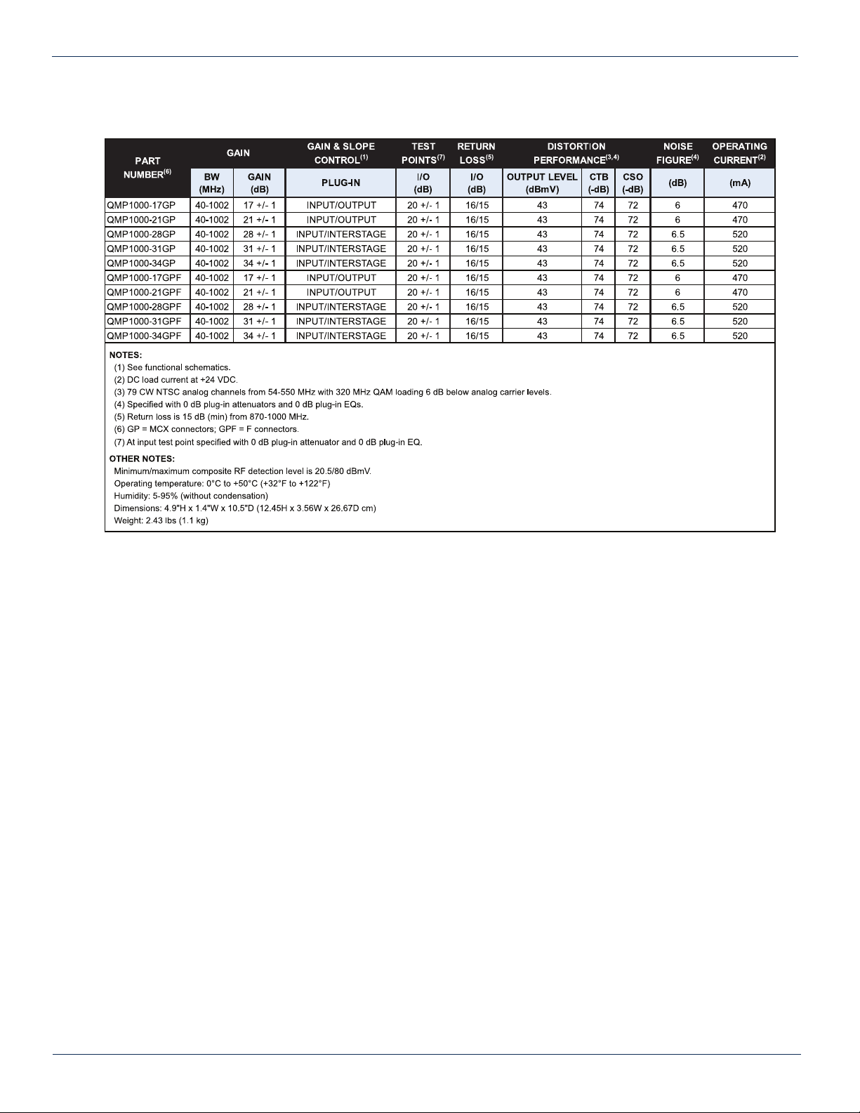
The QMP1000 MAXNET II modules are Forward RF Ampliers, which offer various gains that are determined at the
time of ordering. The lower gain ampliers (17 dB and 21 dB gain) operate in a single stage manner as shown in the
functional diagram – Figure #1, Page 6. The higher gain ampliers (28 dB, 31 dB and 34 dB gain) operate in a dual stage
process as shown in the functional diagram – Figure #2, Page 6. The QMP1000 ampliers are dual-width modules, taking
up two slots in the Active MAXNET II Chassis and they are powered through a hot-swapping backplane. An appropriate
MAXNET II Power Supply in the Active MAXNET II Chassis powers these modules. The QMP1000 modules feature the
standard MAXNET II functionality including high-density packaging through the use of MCX coaxial cable connectors (F
connectors are available as option) in conjunction with Mini RG-59 Type coaxial cable. Also featured are: front access
alarm LED indicator, -20 dB test points and the capability of module status monitoring through SNMP based Managers. The
MAXNET II SNMP interface is HMS compliant.
Please refer to the web page for up-to-date specications – www.atxnetworks.com
Table #1: Ordering Information
MAXNET® II – QMP1000 Forward RF Amplier – Installation & Operation Manual 1-1
CHAPTER 1: PRODUCT DESCRIPTION
Part Number Description
QMP1000-17GP 1000 MHz, 17 dB GaAs Single Stage, MCX Connectors
QMP1000-21GP 1000 MHz, 21 dB GaAs Single Stage, MCX Connectors
QMP1000-28GP 1000 MHz, 28 dB GaAs Dual Stage, MCX Connectors
QMP1000-31GP 1000 MHz, 31 dB GaAs Dual Stage, MCX Connectors
QMP1000-34GP 1000 MHz, 34 dB GaAs Dual Stage, MCX Connectors
QMP1000-17GPF 1000 MHz, 17 dB GaAs Single Stage, F Connectors
QMP1000-21GPF 1000 MHz, 21 dB GaAs Single Stage, F Connectors
QMP1000-28GPF 1000 MHz, 28 dB GaAs Dual Stage, F Connectors
QMP1000-31GPF 1000 MHz, 31 dB GaAs Dual Stage, F Connectors
QMP1000-34GPF 1000 MHz, 34 dB GaAs Dual Stage, F Connectors

1.1. Functional Diagrams
Figure #1: Single Stage Forward RF Amplier Functional Diagram
Figure #2: Dual Stage Forward RF Amplier Functional Diagram
1-2 MAXNET® II – QMP1000 Forward RF Amplier – Installation & Operation Manual
CHAPTER 1: PRODUCT DESCRIPTION
RF
DETECTOR
+24 VDC
CHASSIS
COMM.
RF OUTPUT
RF INPUT
-20 dB OUTPUT
TEST POINT
-20 dB INPUT
TEST POINT
FAN
ACTIVE FUSE,
POWER & FAN
CTRL
PWR
ALARM
MONITOR & CONTROL
PAD EQPAD EQ
Single Stage Forward Amplifier
RF
DETECTOR
+24 VDC
CHASSIS
COMM.
RF OUTPUT
RF INPUT
-20 dB OUTPUT
TEST POINT
-20 dB INPUT
TEST POINT
ACTIVE FUSE,
POWER & FAN
CTRL
FAN
MONITOR & CONTROL
PWR
ALARM
PAD EQ
Dual Stage Forward Amplifier
PAD EQ

1.2. Technical Specications
Table #2: Technical Specications
MAXNET® II – QMP1000 Forward RF Amplier – Installation & Operation Manual 1-3
CHAPTER 1: PRODUCT DESCRIPTION CHAPTER 1: PRODUCT DESCRIPTION

CHAPTER 1: PRODUCT DESCRIPTION
1-4 MAXNET® II – QMP1000 Forward RF Amplier – Installation & Operation Manual
This page left intentionally blank.

INSTALLATION
2. Installation
2.1. Product Inspection
Carefully unpack the amplier module from the shipping box. If the box or amplier module is damaged, please notify the
freight company to make a damage claim. If you suspect that there is a problem with the amplier module that may affect it’s
safe operation, do not install such a suspect Amplier into the Active MAXNET II Chassis.
2.2. Module Installation into the Active MAXNET® II Chassis
Slide the dual-width QMP1000 amplier module into an open slot in the Active MAXNET II Chassis, one that spans two
single-width module locations beginning with an odd number (indicated by a white marker on the chassis), until the module
drops into its lock position. The module must be inserted into an odd number slot in order for the amplier module to
properly mate to the active chassis back plane. If the module is installed properly, the amplier will make contact with the
24 VDC power bus in the chassis and if there is a MAXNET II Power Supply Module installed in the chassis, and it is plugged
into the respective power source, the module’s PWR (Power) LED indicator will light green. To remove an amplier module
from the chassis, gently lift the front handle and pull back on the module until it is clear of the chassis guide slot.
Initially, when inserted in the Active MAXNET II chassis, the amplier will start alarming (the front panel ALM (Alarm) LED
indicator will start ashing red), as there is no RF input signal. The amplier will stop alarming once RF signal is applied to the
input and all other parameters are within operating conditions.
Figure #3: Front & Rear Panel Pictures
Shown with MCX (left) and F (right) Rear Panel Connectors
MAXNET® II – QMP1000 Forward RF Amplier – Installation & Operation Manual 2-1
CHAPTER 2: INSTALLATIONCHAPTER 1: PRODUCT DESCRIPTION
QMP1000-17GPF
QMP1000-17GP QMP1000-17GPF
QMP1000-17GP

2.3. RF Connections
The RF jacks on the QMP1000 ampliers front/rear panel are MCX [female]. As an option, the RF jacks on the rear panel
can be F type [female]. There will be one RF input and one RF output at the rear, plus two front panel -20 dB test points per
QMP1000 amplier. The output (OUT) test point is –20 dB relative to the RF output. The input (IN) test point is –20 dB relative
to the RF input, if input PAD and EQ are 0 dB (see Functional Diagrams on Page 6). The RF Input connector on the rear
panel is the top connector and the RF Output connector on the rear panel is the bottom connector. Connect a test jumper
from output or test point ports to a signal level meter or spectrum analyzer to verify signal quality and adjust RF levels before
connecting subsequent equipment.
The operator can adjust the RF level by inserting PAD’s and EQ’s as shown in functional diagrams (Figure #1 and
Figure #2).
2.4. Amplier Set-up
2.4.1. Amplier LED Indicators
The MAXNET II QMP1000 Ampliers have two LED indicators: PWR and ALM.
a) The PWR (Power) LED veries that the amplier module is receiving power from the MAXNET II Power Supply
through the 24 VDC Chassis Bus. The PWR LED is always solid green when the module is powered. If no powering
is available then the PWR LED is off. The PWR LED does not have a ashing condition.
b) The ALM LED will FLASH RED if there is a problem with the amplier or if any of its monitored functions are beyond
the specied limits (e.g. absence of RF input signal)
Table #3: LED Status Indications
__________________________________________________
1 If the ALM LED is ashing red at a slow rate of approximately 1s on-1s off, this is indicative of a communications failure between this module and
the chassis. See Troubleshooting section.
STATUS
FLASHING
RED1
SOLID
GREEN OFF
LED
PWR N/A Power ON Check Power
Supply
ALM Alarm N/A Normal
2-2 MAXNET® II – QMP1000 Forward RF Amplier – Installation & Operation Manual
CHAPTER 2: INSTALLATION

2.4.2. Amplier Front Panel Controls (Padding & Equalizer)
Figure #4: Front Panel Plug-ins
The QMP1000 Amplier plug-in padding and plug-in equalizer locations are accessible by removing the front cover. Remove
the access cover from the front of the QMP1000 Amplier module by turning the thumbscrew counter-clockwise. This will
expose two blocks of two PAD/EQ locations. By default, ampliers are shipped with plugged in 0 dB values in all four
locations. Within a module, the PAD’s/EQ’s on the left side are connected to the RF Input and the ones on the right side are
connected to the RF Output (Single Stage Amplier), or interstage (Dual Stage Amplier).
Table #4: Plug-in PAD Specications
Table #5: Plug-in 1 GHz EQ Specications
Table #6: Plug-in 1.218 GHz EQ Specications
Single Stage Amp Dual Stage Amp
MAXNET® II – QMP1000 Forward RF Amplier – Installation & Operation Manual 2-3
CHAPTER 2: INSTALLATION CHAPTER 2: INSTALLATION

Table #7: Plug-in PAD/EQ Ordering Information
CHAPTER 2: INSTALLATION
2-4 MAXNET® II – QMP1000 Forward RF Amplier – Installation & Operation Manual
Part Number Description
MP*PAD Plug-in Pad, 1218 MHz (* = dB value, 0-20 dB) (must order in quantities of 10)
MP*EQ Plug-in EQ, 1000 MHz (* = dB value, 1.5-10.5 dB) (must order in quantities of 10)
MP*EQLH Plug-in EQ, 1218 MHz (* = dB value, 1.5-10.5 dB) (must order in quantities of 10)
MPPT Pad/EQ Insertion and Extraction Tool

STATUS MONITORING
3. Status Monitoring
3.1. Chassis Interface Options
The Active MAXNET II product line can be monitored and controlled in either of two ways:
a) A free, web-based interface. This comes pre-installed on every active chassis and provides a user friendly method
of conguring the administrative set-up and all monitoring and control. It is based on SNMP, but requires little
knowledge of SNMP. Any Internet browser, such as Internet Explorer, is all the software that is required.
b) Any third-party SNMP Management software (e.g. www.castlerock.com,
www.ndt-inc.com/SNMP/MIBrowser.html) may be purchased separately. These suites tend to be expensive and
not as user friendly as the web interface. The web interface is also still required for administrative set-up. The 3rd
party interface is recommended only for systems that have an existing SNMP architecture. All MIBs (Management
Information Bases) are freely downloadable from the SCTE website (www.scte.org/standards). ATX was able to
support all modules using the SCTE standard HMS MIBs, so no custom MIBs are required.
3.2. SCTE HMS MIB Software Denition of Module
The headend RF Amp MIB is used to provide only an Output RF detector value, allowing HI and LO alarm thresholds to be
set.
3.3. Web Interface
The MAXNET II active chassis uses an integrated web page to supplement the SNMP management. All congurations of
the chassis (static IP address, trap/email recipients, rmware upgrades, etc) must be done through the web page. Simply
use any web browser (Internet Explorer, Firefox, etc.) and enter the IP address of the chassis as the URL – see Section
3.5.1. for default parameters when shipping from ATX. Login as administrator (select administrator and type in: admin) to
modify conguration and have full read/write access to monitor and control modules. Login as Operator to have full read/
write access or login as observer to have read-only access. There is only one password per login level – see Section 3.5.1.
for default parameters when shipping from ATX.
Figure #5: Web Interface Parameter Page (example)
MAXNET® II – QMP1000 Forward RF Amplier – Installation & Operation Manual 3-1
CHAPTER 3: STATUS MONITORINGCHAPTER 2: INSTALLATION

3.4. Updating Active Chassis Firmware
a) Login to web page interface of the chassis as an administrator.
b) Check software status page for current rev level. If an upgrade is necessary, proceed with next steps.
c) Go to Firmware tab.
d) Select ‘HTTP Server’ and verify it reads: www.atxnetworks.com/rmware/MN2/image.bin
e) Select Upload and wait for conrmation page to appear. The chassis will perform an MD5 checksum on the
downloaded le to verify that no bit errors occurred.
f) If you are updating a version prior to 1.4.2, then the calculated MD5 Checksum will be displayed on the screen.
Contact Engineering at ATX to verify what this value should be (it will be the same for each chassis you upgrade
with a given revision).
g) If you are updating a chassis later than 1.4.2, then the checksum is veried automatically via a text le taken from
the ATX web server.
h) If md5checksum is veried, select Flash to memory. Do not ash if it fails the MD5 checksum, as this could
permanently corrupt the memory.
i) Wait approximately 5 seconds, then disconnect the network cable and proceed to the next chassis. Leave the
recently updated chassis powered until it completes a reboot.
j) Optionally, the chassis may now be factory reset to restore all IP settings to factory defaults. Read the Factory Reset
section fully before doing this to know what data will be lost when doing this.
3.5. Factory Reset
A factory reset will restore the chassis to the state which it left the ATX production facility.
3.5.1. Parameters that will be Changed
IP address = 192.168.0.1
Net Mask = 255.255.255.0
Gateway = 192.168.0.254
Passwords set to same text (but all lower case) as the login level (e.g. Operator password is operator).
All analogue and discrete alarm thresholds of modules will be reset to default values.
Alarm log will be cleared.
3.5.2. Purpose
Common reasons for requiring a factory reset are:
a) The chassis is unresponsive, or the IP address is not known
b) The Administrator password has been forgotten
c) The yellow COMM LED does not blink after the 2 minute boot cycle, even after a power cycle or press of the
RESET button
3.5.3. Method
If you are sure you want to factory reset, hold down the RESET button near the RJ45 port for at least 10 seconds. The yellow
COMM LED will be solid-on during this time, and once it turns off you can release the button and the reboot process will
begin.
3-2 MAXNET® II – QMP1000 Forward RF Amplier – Installation & Operation Manual
CHAPTER 3: STATUS MONITORING

STATUS MONITORING FEATURES
4. Status Monitoring Features
4.1. SNMP Parameters
MAXNET® II – QMP1000 Forward RF Amplier – Installation & Operation Manual 4-1
Display Name Description HMS MIB Variable
Model
ATX model number (note, in empty slots you can
enter passive, dual-passive, or empty to populate the
overview page with passive picture placeholders).
entPhysicalModelName
Description Description of the module. entPhysicalDescr
Name Indicates the slot of the chassis the module is in. entPhysicalName
Alias
Optional user dened eld - added to fth variable
binding of traps and emails
e.g. set this to “Node 69” for a given Receiver and any
alarms generated by this receiver will have “Node 69” in
the description. Otherwise, traps would only contain the
IP address of the chassis, the Model and Name (slot
number).
entPhysicalAlias
Manufacturer ATX entPhysicalMfgName
Asset I.D Optional user settable eld (suggestions: enter in a
custom serial number or purchase order # for tracking). entPhysicalAssetID
Serial No Module’s serial number. entPhysicalSerialNum
Hardware Rev Hardware rev of module. entPhysicalHardwareRev
Firmware Rev Firmware rev of module. entPhysicalFirmwareRev
Temperature [C] Module’s current heatsink temperature. heCommonTemperature
Alarm Detection Control
detectionEnabled: normal operation, with active alarms
detectionDisabled: used to temporarily disable alarms/
traps from this module
detectionEnabledandRegenerate: enter
detectionEnabled state while regenerating all alarm
table entries
heCommonAlarmDetectionControl
Fan Unit Status Alarm status of the fan. heFanUnitAlarm
Display Name Description HMS MIB Variable
Voltage In [Volt] Measured voltage supplied to the module from the
chassis (nominally 24V). hePsUnitVoltageIN
Current In [mA] Current taken from the 24V rail by the module. hePsUnitCurrentIN
Power In [Watts] P.S. Voltage * P.S. Current hePsUnitPowerIN
RF Amp Output
Description Description of the approx gain value of the amp. heRFAmpOutputDescription
RF Amp Output Level
[dBmV] Composite RF level at output of amp. heRFAmpOutputLevel
CHAPTER 3: STATUS MONITORING CHAPTER 4: STATUS MONITORING FEATURES
Table #8: Common Module Parameters
Table #9: QMP1000 SNMP Parameters

4.2. SNMP MIBs Required for QMP1000
Table #10: General SCTE HMS MIBs Required
Table #11: QMP1000 SCTE HMS MIB’s Required
4-2 MAXNET® II – QMP1000 Forward RF Amplier – Installation & Operation Manual
HMS# SCTE#
SCTE-ROOT 028 36
SCTE-HMS-ROOTS 072 37
SCTE-HMS-HEADENDIDENT-MIB 114 38-11
SCTE-HMS-HE-COMMON-MIB 111 84-1
SCTE-HMS-PROPERTY-MIB 026 38-1
SCTE-HMS-HE-FAN-MIB 117 84-3
SCTE-HMS-HE-POWER-SUPPLY-MIB 116 84-2
HMS# SCTE#
SCTE-HMS-HE-RF-MIB 133 83-4
SCTE-HMS-HE-RF-AMP-MIB 131 94-1
CHAPTER 4: STATUS MONITORING FEATURES

MAINTENANCE & TROUBLESHOOTING
5. Maintenance & Troubleshooting
5.1. Maintenance
Daily, ensure that the Power LED’s are ON for all of the modules and that there are no Alarm lights. Ensure that the yellow
‘COM’ LED near the rear RJ45 port (rear of active chassis) is blinking, as well as that the green 24V LED on the rear of the
active chassis is ON.
Weekly, ensure that all module cooling fans are operational and unobstructed.
Monthly, vacuum all module cooling fans.
5.2. Troubleshooting
The following guide will help the operator to diagnose problems in active modules or chassis’. If none of the items in this
section are of help, please contact ATX for Technical Support.
5.2.1. Slow Flashing Red LED on Module Front
If any alarm LED on the front of the module is blinking at a rate of approximately 1 second ON, 1 second OFF, then this is
indicative of a slot addressing communications failure. RF and Optical functionality will likely still work, but the unit will have
no software monitoring or control during this time.
Try removing the module and replacing it. If this does not x the problem, then switch the module to a different slot in the
chassis. If the red LEDs return to normal operation, then the problem is in actual slot of the chassis and likely the connector
on the back rail is damaged. Contact ATX and report a defective chassis.
If this does not x the problem then contact ATX and report a defective module.
5.2.2. Chassis’ Yellow COM LED Not Blinking
It is normal for the round LED near the RJ45 port at the rear of the chassis to be solid ON or OFF during various states of
system boot-up. If the chassis has been powered up (solid green on the round “+24V” LED near the terminal block at the rear
of the chassis) for at least 2 minutes, then the yellow LED should be blinking to indicate the chassis software is running. If it
is not, a reboot is necessary.
Ways to reboot the chassis:
- If the chassis can be interrupted briey, then simply remove power to it by pulling all MPAC/MPDC modules out
part-way.
- If the chassis must remain live then try pressing the black RESET button near the RJ45 port. If this does not work,
then the communications module itself (mounted on the back of the chassis) can be removed from the back of the
chassis. Remove the two Phillips screws that hold the module on, then pull it off and replace it. This will not interrupt
the operation of the modules within the chassis.
If this still does not start the yellow LED blinking after boot-up, then a factory reset will be necessary. See Section 3.5.
MAXNET® II – QMP1000 Forward RF Amplier – Installation & Operation Manual 5-1
CHAPTER 4: STATUS MONITORING FEATURES CHAPTER 5: MAINTENANCE & TROUBLESHOOTING

5.2.3. No Response from Chassis Over Network
Typically, this is a ‘subnet’ issue. In order for any device to see another device on the same network, they must be on the
same subnet. Consult your IT department for details of your network, but typically the subnet refers to the rst three of
the four octets in an IP address (e.g. if the computers in your network are given IP addresses of 192.168.10.1 through
192.168.10.250, then the subnet is the 192.168.10 part).
Each MAXNET II chassis ships with a default IP of
192.168.0.1, so the PC connected to it must have
an IP address of 192.168.0.x where x is not equal
to 1. This is not generally the case, so it must be
forced.
To modify the PC’s IP in Windows, choose Start
-> Settings -> Network Connections -> Local Area
Connection -> Properties -> Internet Protocol
(TCP/IP).
If the chassis IP is no longer at the default IP,
modify the subnet portions of these settings (IP
address and Default Gateway) to match.
If the chassis is still not visible, it is possible the IP address of the chassis has been forgotten (see Factory Reset section),
the network connection is not good (see Ethernet Port section for LED diagnostics) or a network port is blocked or rewalled
(check with your IT department)
5.2.4. Some Modules Do Not Show Up On Web Page
If the chassis is visible on the web or through SNMP walks, but one or more installed modules is not, try removing and
replacing the module in a different slot. Verify that the green power LED is solid and the red LED is either off or blinking quickly
(approx half second on, half second off). If the LEDs are not as stated, see the appropriate troubleshooting section.
5.2.5. Module Power LED Off or Intermittent
Check the ‘24V’ green LED on the rear of the chassis. If it is off, then the problem is that the chassis is not getting power.
See MPAC/MPDC troubleshooting section. If it is on or if other modules in the chassis are okay, the module itself is suspect.
Continue.
Remove the suspect module and trade slot positions with another functioning module.
a) If the suspect module is okay and the previously good module fails, contact ATX and report a defective chassis.
b) If the suspect module fails and the previously good module is okay, contact ATX and report that the suspect module
is defective.
5.2.6. MPAC/MPDC Not Powering Chassis
*Note that 220 VAC applied to an MPAC-110 will damage the module, but 110 VAC applied to an MPAC-220 will simply not
turn on.
a) Check the fuse continuity on the MPAC or MPDC module
b) Verify that the 110 VAC / 220 VAC electrical outlet is active using a voltmeter and checking the circuit breaker. (In
the case of the MPDC insure that there is -48 VDC on the rear terminal block)
c) Verify that IEC power cord is properly inserted into the receptacle on the rear of the module and properly connected
to a 110 VAC / 220 VAC electrical outlet.
5-2 MAXNET® II – QMP1000 Forward RF Amplier – Installation & Operation Manual
CHAPTER 5: MAINTENANCE & TROUBLESHOOTING

5.2.7. Module Will Not Insert Fully into Chassis
a) Remove the module and inspect it for damage or bent guide rails.
b) Inspect the chassis for bent metal or obstructions.
c) Be sure that the active module is inserted such that the left side is above an odd numbered slot and the right side is
above an even number slot.
d) Try the module in a different slot. Due to machinery tolerances, some modules may be more snug in some slots than
others. If the tolerances are unacceptable, contact ATX.
5.2.8. Temperature/Fan Fault Alarm on any MAXNET® II Active Module
Check to see if the module fan is operating. If not replace with a new fan from ATX
(Fan Part #: MPFANA) using the below procedure.
5. Install replacement fan in the opposite order shown. Ensuring that:
a) The red and black wires are aligned.
b) The labelled side of the fan faces inward toward the module
c) The wires do not bunch up behind the fan, interfering with fan rotation.
MAXNET® II – QMP1000 Forward RF Amplier – Installation & Operation Manual 5-3
CHAPTER 5: MAINTENANCE & TROUBLESHOOTING CHAPTER 5: MAINTENANCE & TROUBLESHOOTING
1. Remove two screws holding plate and fan
in place.
2. Remove fan cover and screws.
3. Pull out fan with tweezers. 4. Remove push-t power connections.

CHAPTER 5: MAINTENANCE & TROUBLESHOOTING
5-4 MAXNET® II – QMP1000 Forward RF Amplier – Installation & Operation Manual
This page left intentionally blank.
Table of contents
Other ATX Amplifier manuals