ATX AL-WS-DR1-PIR User manual

ATX LED Consultants Inc
815-A Brazos #326
Austin TX, 78701
512 377 6052
http://atx-led.com
Motion Sensing
LED Dimmer/Driver
AL-WS-DR1-PIR
•Vacancy / Occupancy
mode
•Ambient Light Sensor
•Night-Light
•LED driver ( 30 watts )
•FAN driver ( 12 watts )
•Push Button Switch
•Fan Timer mode
•3-Way supported
•Gang Operation
•DALI option
Product Description - AL-WS-DR1 wall switch with Vacancy/Occupancy
This switch operates just like any standard residential light switch – however it takes 24-51v DC instead of 120VAC, and directly drives up
to 30 watts of LED bulbs or a 12 watt fan. This Decorator style switch in a standard residential style outline fits into any home, looks like
any switch yet meets NEC article 411 for Low Voltage lighting. It also meets Title 24 vacancy code requirements for lighting controls.
When used as a LED switch - the built in Ambient Light sensor, and presence sensor, exceeds Title 24 requirements. The switch can
operate in:
•Vacancy mode ( manual on, automatic off )
•Occupancy mode ( automatic on and off )
•Occupancy with Ambient ( automatic on if the room is dark, automatic off)
When used as a FAN controller – the push button starts the fan and it runs for a user defined time. Vacancy will turn the fan off after a
programmable delay. Occupancy will turn the fan ON if presence is detected for a settable duration. Fans are automatically detected.
Unlike conventional On/Off vacancy switches – the dimming feature of this device means that the light does not go off all at once, instead,
it dims slowly down to zero. Should someone be in the room and undetected – the room does not go dark – allowing the occupant to
create sufficient motion to maintain light.
Stand alone it operates as a simple switch for 30 watts of LED’s. For example, 5x 6 Watt LEDs can connect in series to this switch /
dimmer device. Use AWG 16 or 18 to bring 48v ( or 24 to 52 volts ) from a central power supply over to the switches, then use AWG 20
to connect to your LEDs – no crimping tools are required to wire this device.
For 3-way operation – a simple 2 wire link with AWG24 or better allows 2, 3, or an unlimited numbers of switches to control one set of
LED’s. Any single pole switch found at Home Depot can be used to add a 3-Way remote switch, or the AL-WS-M momentary switch can
be used for unlimited 3-Way connections. Multiple AL-WS-DR1 devices can communicate without any Hub using this interface.
To enable Home / Business automation – the AL-WS-DR1-PIR includes a DALI serial bidirectional port for remote and voice control and
central management. Use the AL-DALI-Pi Hub to connect to Alexa or Google home voice control. The DALI protocol is supported, with
automatic addressing. Use low cost wire in uncomplicated topology to implement remote management. Power and DALI have in and
out connectors to avoid wire nuts.

-
Specifications
Power source and load Spring loaded connectors ( 2 pairs )
for AWG 16-20 wire
LED constant current output 660 mA with 0 to 100% dimming
Spring loaded connectors ( 1 pair )
Input voltage range 24v to 52 volts ( power for LEDs)
Standby power consumption <50 milliwatts
Conversion efficiency Over 95%
Protection Reverse protection and static protection
Operating Temperature 0°C ~ 50°C
Size 115 x 46 x 50 mm
Dimming 100% to 1%
Current control with temperature tracking
FCC and interference All outputs are RF filtered for minimal
interference
Maximum output voltage Input minus 4 volts
Minimum output voltage 6 volts, minimum current self calibrating*
Hot Swap Yes – can unplug and connect LEDs with
power applied.
DALI interface
Individual, group and scene
support
AWG 18-24 gauge wire spring fit
short and long addresses 16 to 24 volts 2 mA
User Programming Limited user programming supported by a
round button
N-Way input see features list
FAN output 12 volts, 1 amp with speed control
FAN Timer 0 to 90 minutes – using DALI commands
Wiring the AL-WS-DR1-PIR
See
http://atxled.com/How2 for more examples

Powering the AL-WS-DR1-PIR
Power the switch via the Power input connectors, 48 to 52v is recommended. No DALI connection is required.
You can feed from the input to the output up to 2 amps. After power up – you might see a flicker while it learns the
capability of the attached LED. After that phase – the result is stored in on-board EEprom and will be updated for
temperature and aging changes or each time the slider is moved to low dim.
Default Operation – stand alone
By default – the AL-WS-DR1-PIR operates stand alone – no controller or master is required. Connect the LED
output to your LED’s. See https://atxled.com/How2 for wiring suggestions. No other wires are required. Press the
button and the light will turn on. Occupancy, Vacancy modes can be selected from the front panel. The light can
be turned off from the switch as well.
Presence Sensing
The AL-WS-DR1-PIR detects the presence of people by infrared passive sensing. The sensitivity is learned over
time. Each time the On button is pressed when the switch has inferred that no person is present, the minimum
sensitivity will be increased. Each time the light is manually turned off, after the expected vacancy timeout period,
and we can infer that sensitivity needs to be reduced.
Daylight Harvesting for Motion sensing
When the AL-WS-DR1-PIR has turned the attached LEDs off – it can measure the light in the room. If there is
enough light in the room – then detection of presence will not automatically turn the lights on, the user would have
to press the switch to turn the lights on.
Vacancy Sensing and learning
When the AL-WS-DR1-PIR has detected no presence for 120 seconds, the slow fade dimming to off begins. This
will slowly turn the lights off to allow anyone in the room to reach the switch or trigger detection before the room is
dark. A button press during fading indicates that the vacancy sensing was not sensitive enough and the device will
increase sensitivity.
Built in or remote Night Light
If enabled, the AL-WS-DR1-PIR will turn on a light to guide people in the room without turning the lights on. This is
most useful in Vacancy mode. The night light brightness is controlled by DALI settings or user selection.
Fan operation
If a fan is detected, then the device will drive a Fan. The user can turn the fan on manually, or it will turn itself on if
motion is maintained for 3 minutes. In this mode, fan will stay on for 10 minutes after the last motion is detected.

On / Off Operation
Press the button once to toggle the light on or off. If the light is turned on by the switch during fade out, then the On
Time is doubled
Local and Remote Dimming
Press and hold the switch to dim the LED down. To dim up – hold the switch down until it fades to low, and
continue to hold so it will brighten back up again. If you reach to high a dim level – then release and press again –
the level will decrease.
Auto Gang Operation
If no DALI address is assigned, the AL-WS-DR1-PIR assumes that the device is in autonomous mode, and not
connected to a DALI bus. In this mode, each time there is an On/Off event locally – the device will transmit via
DALI the dimming level using the reserved command 0xDD. This will be recognized by other AL-WS-DR1-PIR as
an ARC level command and ignored by regular DALI devices. This allows multiple devices to be connected as one
large, multi motion sensing network controlling a large number of LEDs.
Daylight Harvesting Modes
If daylight harvesting is enabled, the device will increase and decrease the ceiling LED brightness to match the
target “Harvesting” brightness set by the user. Every 10 minutes, the system will compare the light in the room with
the requested level, and adjust up and down as needed. The level will be sent on the DALI bus, allowing a large
number of LEDs to be automatically controlled.

User Programming
The round programming button is used for setting user options. It is used together with the main switch. Press the
two switches as shown below, the Night-Light will flash each time the second button is pressed. Repeat until the
operation mode requested is active as confirmed by the flashes of the Night-Light. In Title 24 states, the
Occupancy mode is disabled. This mode will be exited 15 seconds after no action is performed.
Round button pressed and held
Large button is tapped
Large button pressed and held
round button is tapped
Option Function Number of flashes Option Function
Manual Manual Control Only 1 Fan - manual No Automation
LED Occupancy* Automatic on, Automatic
off
2 Fan – 90 second
Delay to ON
Automatic On
Automatic Delay Off
LED Vacancy Manual On
Automatic Off
3 Fan – Vacancy Manual On
Automatic Delay Off
LED Ambient Automatic On if dark,
Automatic Off
4Night-Light Enter Night-Light
Brightness Mode
Night-Light Brightness Mode
If the device is placed into Night-Light Brightness mode, then the brightness of the Night-Light will be controlled by
the large button for the next 15 seconds. Toggle the Night-Light on/off or dim it by pressing and holding the main
switch. Once the level is set, don’t do anything for 15 seconds.

Hub Controlled Operation
Default DALI Operation
After a factory reset – the AL-WS-DR1-PIR only responds to DALI broadcast commands. There is no group or
short address assignment yet. Since the device accepts DALI broadcast commands – any DALI switch or master
that sends broadcast commands can connect to this device remotely for on/off/dimming – the LED outputs are
controlled by the switch or DALI broadcast packets. In Default mode – no standard DALI ARC level transmissions
occur. DALI received commands are treated like 3-way switch controls.
Auto Virtual 3-Way Operation
If no DALI address is assigned, the AL-WS-DR1-VAC assumes that the device is in autonomous mode, and not
connected to a DALI bus. In this mode, each time there is an On/Off event locally – the device will transmit via
DALI the dimming level using the reserved command 171 in broadcast mode - this will be recognized by other AL-
WS-DR1-VAC as an ARC level command and ignored by regular DALI devices. This allows multiple devices to be
connected as one large, multi motion sensing network controlling a large number of LEDs.
Full DALI Operation
For full DALI operation - connect your powered DALI bus to the DA+ connections of the AL-WS-DR1-PIR. The
device responds to the provisioning commands from a DALI master. In order for addressable functions to work, a
‘short’ address [0 thru 63] needs to be assigned. This can be done by a DALI Master with configuration features.
Once a short address is assigned – the device can be understood to operate as two devices in one.
1) LED driver with DALI control – the LED outputs will have a unique DALI short address after provisioning.
The LED driver outputs are connected to LED’s and each switch can now be individually controlled by DALI
commands from the bus. All DALI 60929-2006 commands are supported. The actual address and group
is defined and can be changed by the DALI master. See below.
2) Dimmer / Switch with DALI outputs – after provisioning – the mechanical front switch in this device is
placed into either short address or Group mode – see below – flipping the switch, or the 3-way remote
switches, or the slider dimming value will cause a DALI command to be sent internally to the LED outputs
as well as externally to the DALI bus.
3) A DALI Short Address Reset command will return the device to broadcast receive mode and disable all
On/Off/Dim transmissions.
Use an AL-DALI-PI or DALI-100 or similar provisioning tool to assign short and group addresses.
DALI command set
See the AL-WS-DR2 spec for the full set of DALI commands.

DALI Address Assignment - Auto - Grouping
The switch from the factory has no DALI Short address by default. When a DALI master assigns a short address
to the switch, one built-in feature rule has been implemented in all DALI ATX-LED devices.
•If the short address assigned is from 0-15, then the built-in switch will send a Group On/Off/Dim command
to the DALI bus each time the local status changes – On, Off, Dim – from the switch, slider or N-Way. This
method allows multiple DR1-PIR to be configured as a gang – to all operate as one switch. After assigning
each DR1-PIR a short address less than 16, add to each DR1-PIR the group address of the others to be
ganged together. An AL-WS-010v can also be assigned to the same group.
An Al-WS-010v can thus be used as a 3-Way switch with full slider dimming. Use the dip switches in the
AL-WS-010v to set it to a fixed Group address 0-15 for remote On/Off/Dim. Set the AL-WS-010v via dip
switch to a Group ( say starting at 15 downward) and use the DALI Master to assign the DR1-PIR target to
the same numeric short address as that Group ( say 15)
•If the short address is from address 16-63, then the switch will output these state changes using its short
address, not a group address: An AL-WS-010v can be assigned the same short address to implement 3-
way control with dimming.
DALI commands also are used to determine the 3-Way state. Therefore, a DALI command with the matching
Group or Individual address will set the light on or off – and all local switches – physical or virtual – will reflect that
change – so that the next flip of any switch will turn the light off or on as intended. This may result in UP and
DOWN being reversed – like any conventional 3-way mechanical switch.
Software 3-Way Operation
DALI commands also are used to determine the 3-Way state. Therefore, an Alexa to DALI interface will set the
light on or off – and all local switches – physical or virtual – will reflect that change – so that the next flip of any
switch will turn the light off or on as intended.
The Virtual 3-Way method uses 2 or more AL-WS-010v devices with the same short or group address which
communicate via the DALI bus. Using the Virtual method just means that each AL-WS-010v will XOR it’s physical
switch state with the data it receives to its address from the DALI bus. The result allows unlimited numbers of
switches to dim and control a common light. Since each DR1-PIR or 010v device supports the N-Way input – the
number of control points is limitless.
Note: DALI commands from other devices – such as AL-DALI-Wiz or AL-DALI-Pi receive commands from the
Cloud (Alexa, Google, etc) and output those on the DALI bus. These commands ( on, off, dim) override the local
switch setting – operating as 3-Way switches. Therefore, rocker UP or DOWN will be inverted if a command has
arrived from the cloud.
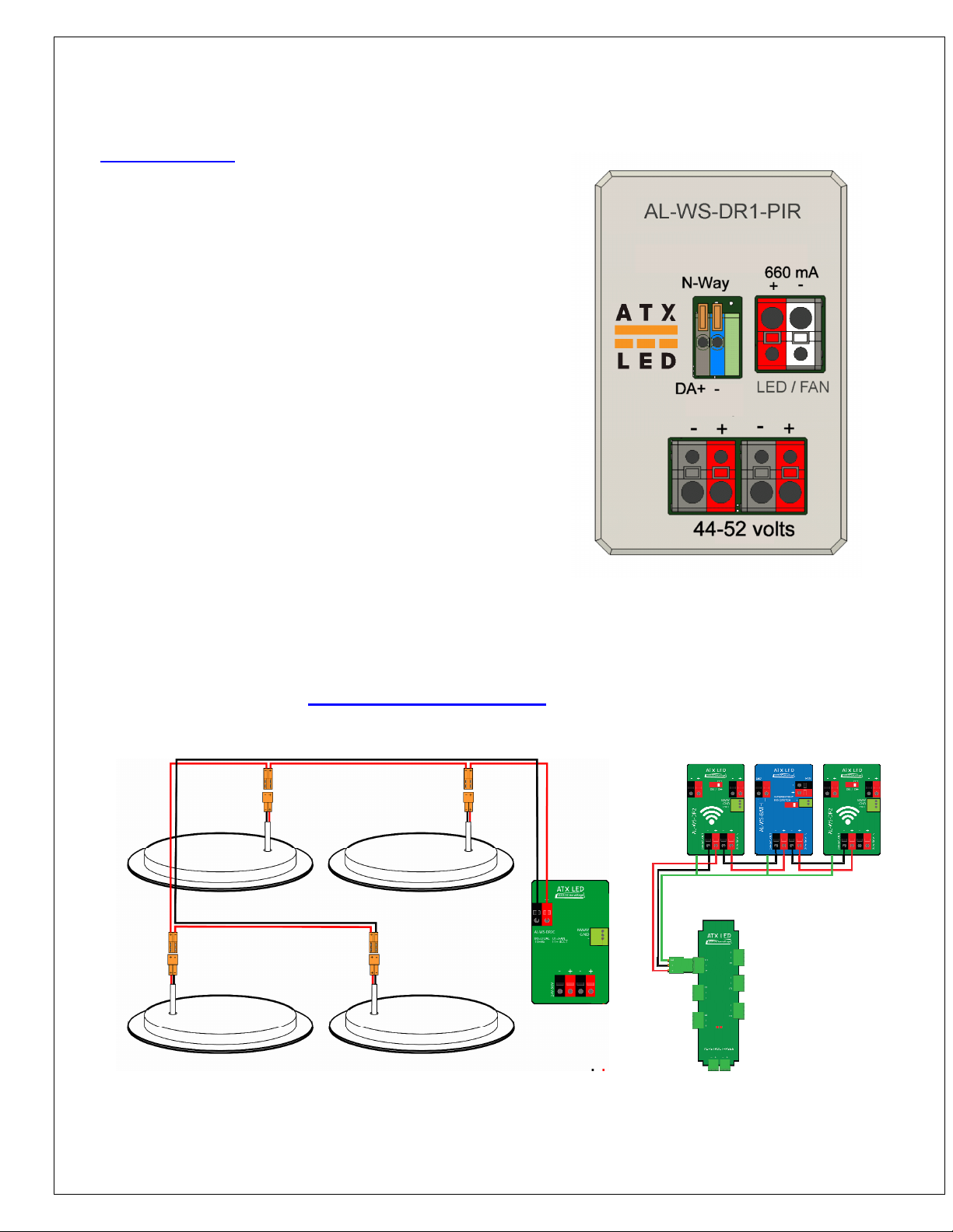
DALI wiring / N-Way operation
Unlike all other ATX LED dimmers, this device only has 2 connectors for DALI and N-Way, this DALI is not isolated,
and the polarity must be assured. The Gray / Blue connector is the DALI I/O connector, Gray is DA+ and Blue is
DA- .
Connect 2 PIR together via the DALI/Nway pins for stand alone peer operation.
Connect an AL-WS-M switch to the DALI/Nway connector for simple remote on/off/dim operation. The device will
automatically detect the difference between DALI and N-Way.

Motion Sensing DALI configuration
Unique to this device are the DALI memory bank 0 contents. They are read / writable
On Time
16
Seconds of On Time renewed each time moment motion is detected
The 8 bit value is multiplied by 30 for the number of seconds
Maintain
Sensitivity
17
Sensitivity for keep alive. Typically 10 to 15 should be used. Higher values are less
sensitive. If no motion in at this sensitivity is detected, the light will turn off
automatically in either vacancy or occupancy mode
Detect
Sensitivity
18
Sensitivity for new motion. Typically 40 to 80 should be used, higher values are less
sensitive. In occupancy mode, this level will cause the light to turn on
Brightness
19
Night-Light Brightness
a value from 0 ( off ) to 255 ( full power )
Harvesting
20
if there is ample light in the room
– the motion sensor will not turn on the LED lighting
– the ceiling light can be dimmed to this level
255 = always turn on the LED lighting
Fade Out
21
this is the number of seconds it will take to fully turn the light off
when no motion is detected
Dark Level
22
Night-light Threshold
The Ambient light setting that will turn the night-light off
if the light exceeds this value
NightLight
23
mode value Onboard Light Ceiling Light DALI bus
Off 0 Off No update No update
Built In 1 Active No update No update
Overhead 2 Off Active Update
Both 3 Low level Active Update
Motion
24
mode Value On Rule Off Rule Brightness
Occupancy 0 Auto Auto Memory
Vacancy 1 Manual Auto Memory
Manual 2 Manual Manual Memory
Occupancy Harvest 3 Auto Auto Automatic
Vacancy Harvest 4 Manual Auto Automatic
Manual Harvest 5 Manual Manual Automatic

ZWD management
Sensitivity Settings
The motion sensor can be adjusted from requiring a large amount of energy to activate or requiring little energy.
40 is a typical value, 0 is too sensitive for all applications, and 255 will disable the sensor.
Brightness Settings
The sensor can be adjusted to turn on the lights only when the room is not fully lighted already. The main light
threshold is adjusted by the Daylight Harvesting slider to only turn the LED on when needed. The Night-Light
threshold is adjustable to be on when the room is dark enough to need a guide light. In addition, the brightness of
the Night-Light can be adjusted.
Timing Settings
The motion sensor will keep the light on for the time you define, from 30 to 7200 seconds. After this time, the light
will start to fade off. During this fade out time, the occupant will have ample light to be able to trigger an extension
should the sensitivity be set too high.

N-Way signal options set via DALI command 35
Using the Dali command 35 – several modes are available. A DALI command 35 with the following values will
select these advanced features. These settings override and disable the round programming button
0 THREE WAY Default
2 Full Automatic Turn on when presence is detected and the room is dark
3 Occupancy Turn on when presence is detected
4 Vacancy Manual turn on, turn off after a delay with no presence detected.
5 Ambient Same as Occupancy, but only on if Ambient light is low
6 FAN Force fan mode ( CV 12 volts)
Fan control
Intended for bathroom fans, if the B output is a light, and the light switch is turned on locally and stays on, then the
A output will be turned on for the Hold-ON duration. The delay before turn on is set by the DALI command 51, then
once on, the on time is set by the DALI command 52. If the light stays on, the fan stays on past the Hold-On time
DALI Function Set DTR value before these commands Scale
50 Fan Idle Sets the speed of the fan when it is ‘off’ – can set a low level 20-200
51 Delay before ON
∞
,7, 10, 14, 20, 28, 40, 56, 80, 113, 160, 226, 320, 452, 640, 900 Seconds
0 =
∞
15=900
52 Hold-ON
∞
,
½ , ¾, 1, 1 ½ , 2, 3, 4, 5, 8, 10, 15, 20, 30, 40, 60 Minutes
0 =
∞
15=60
53 Fan Operate Sets the speed of the fan when it is ‘on’ 50-254
∞
means never. The A output can also be controlled by a simple contact switch connected to the N-Way input.
The N-Way switch overrides the timers. Note: Set mode 35 to FAN to set Delay and Hold. Set mode 35 to 0 to set
lamp fade rates – then change to Fan mode to set Delay and Hold

DALI bus products from ATX LED Consultants
Structured Wiring
DALI power supply with easy wiring
Wall Switch +
LED Driver with
tunable white
ATX LED Product family

Memory Bank 0
(DTR1 = 0)
DTR register Bank 0 Name Bank 0 Value
0 Bytes per Bank
( minus 1)
63
1 Checksum Calculated
2 Number of Banks
( minus 1)
3
3 UPC code – msb
4 UPC code
5 UPC code
6 UPC code
7 UPC code
8 UPC code – lsb
9 FW Version
10 HW Version
11 Serial Number – msb
12 Serial Number
13 Serial Number
14 Serial Number – lsb
Assigned by Master
15 N-Way Mode See details
16 On time with Motion detected Value*30 = Seconds
17 Vacancy Sensitivity (keep alive) 6-255
18 Occupancy Sensitivity (detect) 6-255
19 Night-Light Brightness 0-255
20 Daylight Harvesting 0-254, 255
21 Fade out time if no Motion Seconds
22 Night-Light on below this ambient 0-255
23 Night-Light Mode 0 = off, 1 = built in,
2= overhead 3 = both
24 Occupancy or Vacancy 0 = Occupancy
1 = Vacancy
2 = Manual
25 Debug Mode if > 0 Send motion sense data and more
26-63 Storage User Defined

Memory Bank 4
(DTR1 = 4)
DTR register Name Value
3, 4 Up Time ls (3) ms (4) Hours
5, 6 On Time ls (5) ms (6) Hours
12 Wh/10 99 = 990 Wh
add to kWh elow
7, 8 kWh ls (7) ms ( ) kWh
9 Average Watts since oot Watts
10 Peak Watts Peak when LEDs at 100%
Watts
11 UPS mode Power limited output level
20-254
13 Present Watts – rough Watts Total
14, 15 Input Voltage ls (14) ms (15) Milli Volts
16, 17 Present Wattage detail
ls (16) ms (17)
milli Watts
18, 19 n/a
20 Am ient Light level now 0 - 255
21 Am ient with Night-Light off 0 – 255
22 Last Motion detected level Last max level since light turned off
Table of contents
Popular Dimmer manuals by other brands

Crestron
Crestron 4 Channel Fluorescent Dimming Module... Specifications

Leviton
Leviton Decora Mural MCX10-1 installation instructions

Lightronics
Lightronics RE-121 manual

Lightronics
Lightronics AS-40M owner's manual

EcoDim
EcoDim ECO-DIM.05 Zigbee user manual

Universal Remote Control
Universal Remote Control MRFA-3LD-URC installation manual