OccuSwitch DALI
User Guide
Page 10
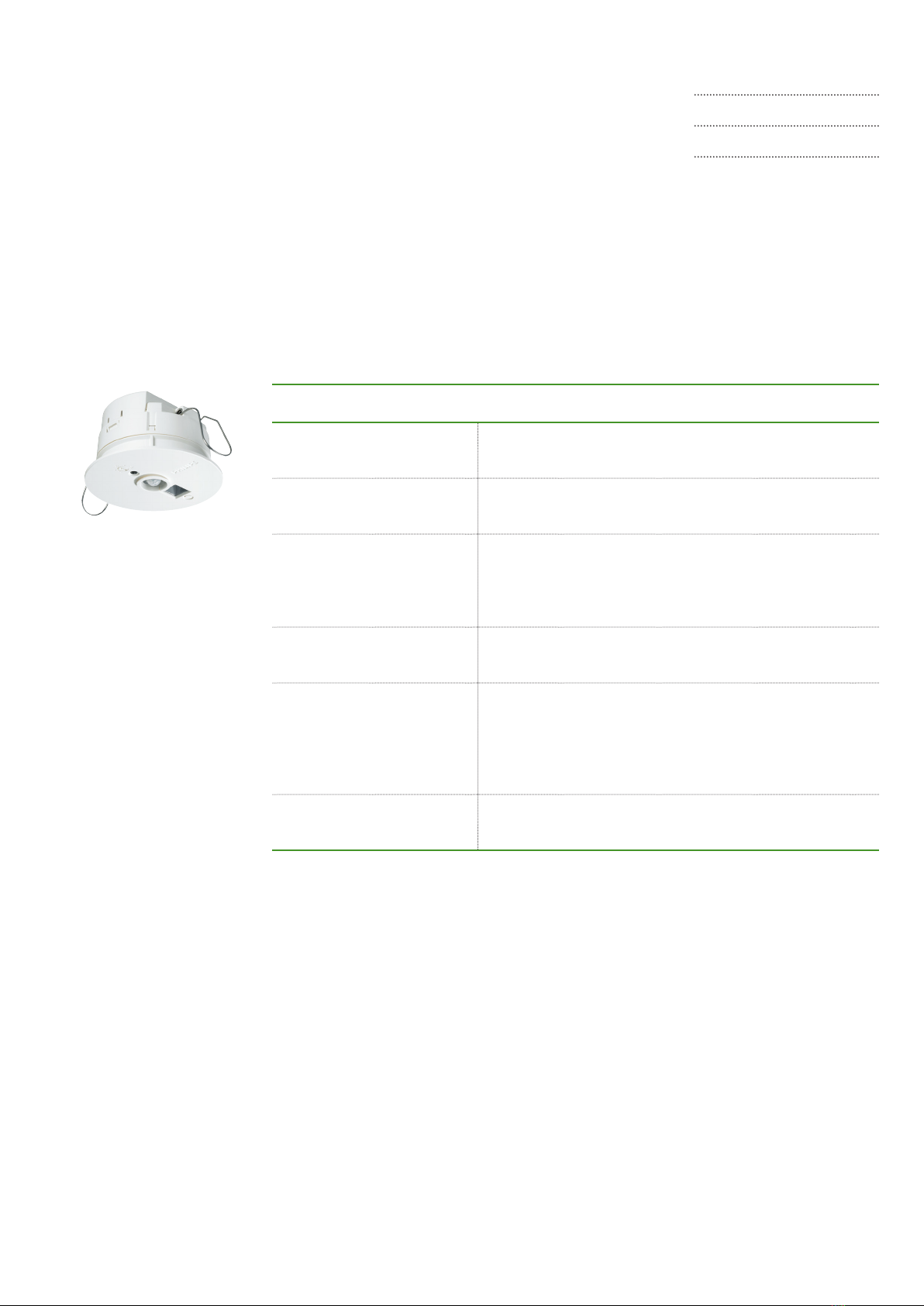
2.1.2 OccuSwitch DALI Advanced (LRM208x)
Figure 2: Two grids in one oce linked with an OccuSwitch DALI Advanced
installation
The OccuSwitch DALI Advanced is a module that allows
covering larger areas such as open plan oces. Up
to 22 modules can be connected in parallel to create
lighting zones in an open oce. These lighting zones
can be used, for example, so that the local lights in one
area are switched on at occupancy and the lights of the
surrounding areas are automatically set to the background
lighting level.
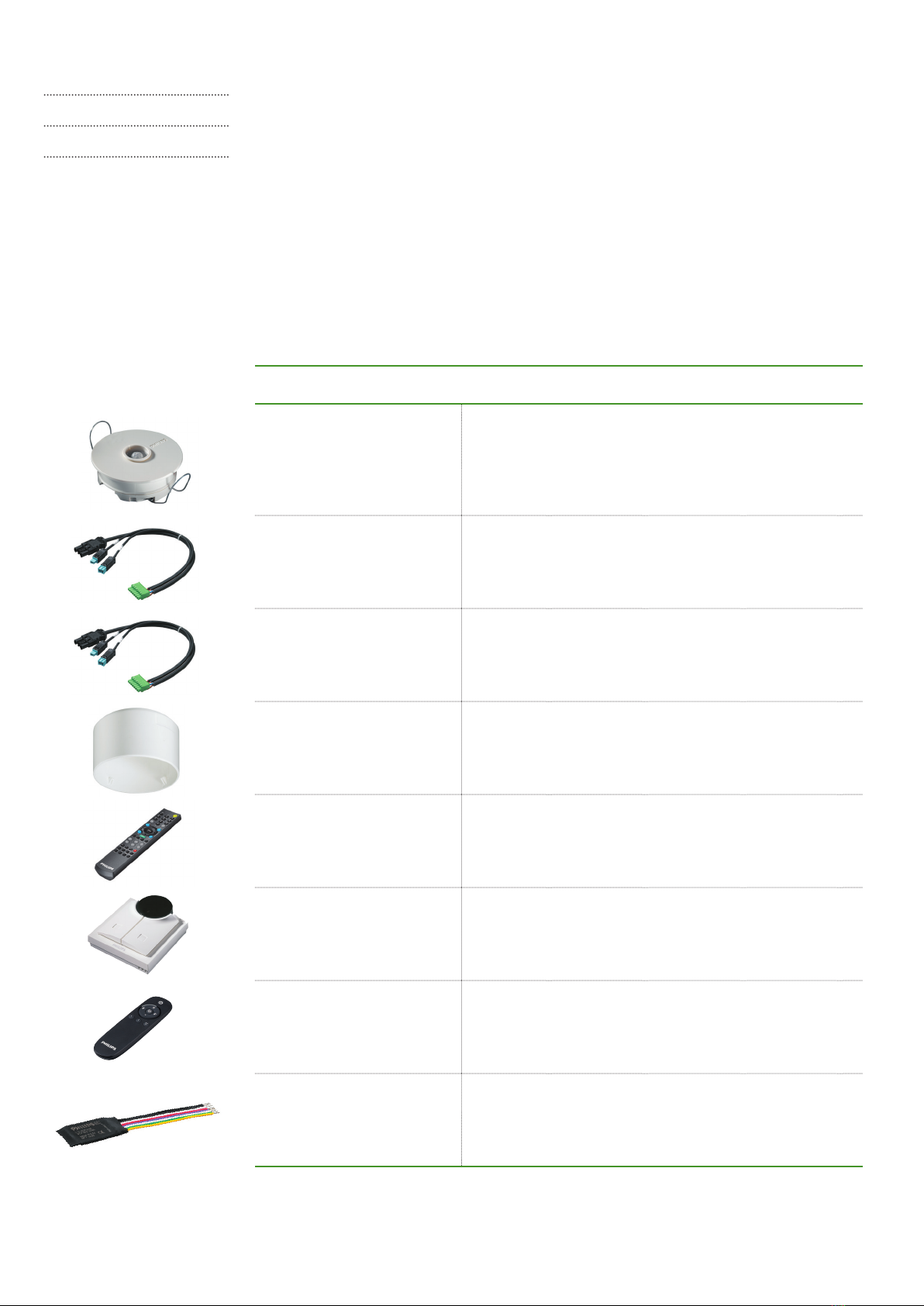
Table 5: OccuSwitch DALI Advanced connectors
Example
Figure 2 shows an example with a larger room existing of
two oce grids with each their own OccuSwitch DALI. The
two devices are connected via parallel linking, so they can
share their occupancy status with each other. This means
that when someone enters the oce the lights on that side
will switch on. A message is send to the neighboring unit.
Depending on conguration, the lights in that area will
switch on to the normal level or to the background level.
Output connectors Un-commissioned system Commissioned system
DALI Output connector “DA” The system regulates all connected
luminaires identically. This can cause
insucient light further away from the
window.
Up to four output groups (window
row, corridor row, plus two additional
groups) can be set. This allows setting
correct light levels for all luminaire
groups.
For commissioning, see chapter 4.
Parallel link connector “X” By default the OccuSwitch DALI
Advanced is set to local occupancy
(Mode 1). Once one OccuSwitch DALI
detects occupancy, all OccuSwitch
DALI devices on the same parallel link
will turn their lights on.
It is possible to set other OccuSwitch
DALI devices using the same parallel
link to go to background level when
one OccuSwitch DALI is occupied
(Mode 9).