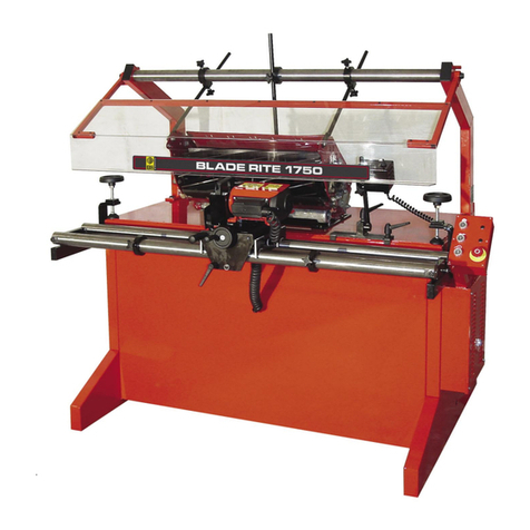
AU Tool PR2 User manual

Automatic
Grinding Machine & Eng.
Co.
Ltd"
PADIHAM ROAD,SABDEN, BLACKBURN, LANCS.
8B69EW
E
NGLAND
.
Tal.
0282
(PadihamJ771838173821
Cables: AUTOGRIND,
PADIHAM'
( \
AUTOOL
GRINDER
,,
_M_O_D_E_L_P_R_2
__
)
Installation
and
Operating
Instructions
Parts
Identification
-
www.DaltonsWadkin.com
www.DaltonsWadkin.com
www.DaltonsWadkin.com

Page
1
'AU
TOOL
' PROFILE
GRINDER
MGDEL
PR/2
Teclmical
Specification
Grinding
W
heal
diameter
'"
~.
9
in"
)
GrinHng
Wheel
width
5
~
.
Grinding
Wh
eel
bore
"
in
••
Output
of
Grinding
Wh
eel
Mo
tor~
,
>,.
standard
It
bp
.
on
re
qu
est
.
12
ins.
Maximum
longth
of
cut t e
rb
ead
Maximum
diameter
of
cutting
circle
Output
of
coolant
pump
motor
Coolant
tank
~ap&city
14t
ins.
(standard)
O.lR
bp.
Over
..
ll
heig
ht
Vorkin
g
vidth
V
orking
depth
40
litrH
1600
mm
.
1450
m
on
.
1100
mm
.
Eloctrical
s
upply
required.
Control
voltage
220-580
volt.
3
ph
..
se
50/60Ilz
.
(Standard)
110
volts
ATT~::NTION
Safety
Precaution"
Note
th<>
various
~
af"ty
poi
nh
glVe
n b
elo
;(
and
in
the
text
and
ob
5
0rva
t h
em
when
operating
t
he
m..
chine.
Isolate
the
machine
before
touching
or
changing
a
~beel
and
vhen
setting
up
.
Carefully
fo11o"
the
the
machine
off
...
ait
s
af
ety
instructions
vhen
until
the
wb
eel
comes
to
changing
a
...
heel
.
re.t
before
mal,i"g
After
s
...
itching
any
adjugtment.
Rest
th~
o
arricge
in
th"
rm.r
position
~h
"n ~e
tting
up,
changing
over
a
cuttcrhe"d
,
"hitting
El.
knife
or
holder
and
"hen
dressing
th"
....
h
eel
.
Gently
lover
the
cutterhead
s~sembly
onto
the
machi
ne .
DO
NOT
DROP
.
These
cutters
cu
t.
" ..
tch
your
ha
nds
and
fingers
and
k
eep
th"m
out
of
the
~ay.
Do
not
fully
tighte
n
either
a
knife
or
a
holder,
nor
loo
~
en
them
from
fully
tight
vhiht
the
cutt"rhe"d
is
on
th
e
grinder.
Fully
tighten
knive~
and
holders
immediately
after
removal
fro
m
the
grinder
•
..
hen
in
th
e
area
and
u
~
ing
the
machine
V..
ar
~uit!l.bly
approved
goggle~
or
a
visor
.
Never
run
a
grinding
head
vithout
all
the
guards
in
place.
Check
the
~bcel
fo
r
~le
..
ran~
o
a.
lld
the
guards
for
security
before
starting
up.
Grind
w
et,
but
do
not
run
cool
..
nt
against
a
$t&tiona
ry
vheel.
Note
that
the
vheel
is
of
vitrified
bond
..
hich
by
its
natur"
i
~
hard
and
brit
t l e .
Becau~c
of
this,
and
it~
thickne~"
,
exe
rci
se
ca.ntion
vhen
applying
s
ide
pressure.
Read
and
f
olIo
...
the
instruction.
given
in
this
manual,
and
"ar
k
in
",ccordance
vHh
good
safety
and
oper"tional
practi
ce
s .
www.DaltonsWadkin.com
www.DaltonsWadkin.com
www.DaltonsWadkin.com

2
7-
- +
23
PW . 1
I , Ha.",\
...
heel
for
fin~
for"'ard
,n
ovemc
n t of
grinding
head
2 .
Spotl
i
ght
switc
h
3 ,
Locli
for
1
"no
fOl
'
""
,
vd
mOY"
rn
'>nt
of
grind
in
g
head
4 .
Locating
lev,,,
'
for
""ivi>!
mOv""".'llt.
5.
[.
e
veT
for
s,"ivel
rrl
o,-"ment
6 . U
pp
e r
cuoh
n t
pi
pe
7 .
Spotlight
8 .
Knit
" SlIPP01't
9 .
H"nd")",,,\
for
left_
h
and
adjubtablu
e"nt
r "
1O
.
1!"",I~·h
c
ul
Ll
"cd
to
rotal
..
""ttcrh,',,d
" h
~n
!p'inding
to
m"
in
t~in
CO
l1ouct
he
t,,,
.,,,, i
<Hif
<l
and
s u
pport
.
11
•
Cutter
)
1<'lld
12
.
T"mp
l
Rl~
holdn
13
.
]!,,"dle
for
cO
ll
trollinK
moveme
nt
of
cllrri"ge
14.Elho~·
re
.•
t
15
.
Sample
turning
16
.
nllnd"h
e
cl
for
a<l,jn.
<t
in
g
rest
po.ition
of
cn
rri
age
17
.
H
,,
" d
"h
~,,1
for
po"itioning
carriage.
18
.
I
,
ocl,scre"~
for
17.
19
.Contr
ol
pus
h bu
ttons
.
20
.
Coohwt
filter
-
"ash
out r
egu
larl
y ,
unsoro"
to
remove.
21 .
Cool
..
nt
pULlp
22
.
Conlant
t a
nk
_ ..
c
ces~
from
r"
..r
23
.
Contrel
ta
p
fur
lo"
"r
cool
..
"t
jet
24.Control
t
ap
for
upper
coola
nt
je
t
25
.
Lock
for
27.
26 ,S"
ing
,
,,,ay
cove
r
for
t
"o
_
~p~e
d
drivg.
27
.
Ha"d"h
~d
for
,,
(!j
U
~tilll(
cle!tranCd
engle
19
www.DaltonsWadkin.com
www.DaltonsWadkin.com
www.DaltonsWadkin.com

Page 2
IN'nlOIltlCT
I(!;
The
machine
ha
B
been
deeigned
primarily
tor
grinding
hexagon
cylinde
r
head~
ae
used
On manual
end
eutoaatic
shap
ing
l
at
h
es
.
By
using
a
ts~plate
ehaped
to
the
rev
e
r~e
of
the
turning
pToftle
requi
r
ed,
th
e kni
ves
are
accurately
fOnl~
to
the
correct
profUe
eac
h
ti_
thoy
are
ground
_
with
o
ut
r
eliance
on
the
traditional
grinding
,
kill
. .
Accuracy
and
repeatability
of
pr
ofi
le
is
gu
arsnteed
reg
ar
dh
••
at
the
ahear
.nd
cutting
angh
.
ot
the
kniv
u and
of
the
8ty
le
.nd
pa
ttern
ot
th
e
he.d
b
ein
g
used
.
By
grinding
knives
'in
.
itu'
on the h
e.d
to
b,
used,
knif
e
sotting
ia
e
liminat
ed
Dnd
,
in
f a
ct
,
groater
."cur.cy
of one
knife
profile
to
the
n,.t
ia
poa.ibl.
than
"i
th
conventional
grinding
and
set
tin
g .
The
front
.nd
side
clearance
englel
ere
va
riable
and,
once
.et
,
remain
co
r
rect
for
all
s
hear
and
cutting
.ngle.
of
knive
l
in
.ny
set_up.
I n
e~pha.iz
i
ng
that
I.e.
ekill
ie
r
equi
red
to
prof
il
e
grind
using
this
..
chine
,
it
would be ia
pn
,
dent
to
e.p
loy
en
ope
rator
wi
thout
previous
grinding
knovledge
or
ski
ll
s . The
uae
of
thia
..
chi
ne ,
of
cour
se,
8t
i
ll
requir
e'
the
traditional
sk
ill
..
in
knife
.nd
holder
nhcHon
and
fitt
ing.
but
the
.ccuucy
"ith
..
hich
it
can
fa""
c","ple
" pr
ofi
lea
,
.nd
th
e
speci.l
features
it
_bod
i
..
,
in
lI.ny
c
••
oa
f~cil
it
~t8
sirnplif
i
e
~ti
on
nf
knife
8e
t_up8 by
allo~ing
knivee
to
co~plete
JIIore
than
one
8ec
tion
of
turning
.
fNSTALLATION
Vh
on
the
m~ch
i
ne
i s
to
be
i
natalled
on
n 6
in
.
thic
k
80l
id concr
ete
tloor
no
apeciel
found~tions
..
re
r"<tuired
.
Cut
4"
squo.
re
ho lee
tor
r.g
both"
sho
'om
on
tho
foundat
ion
plan.
A good
"oodon
Cloor i .
al
ae
8uitable,
and
co.ch
8crev'
..
y be
u.ed
.
.!J.tting
the
Ha
ch
i
n.
T..o
lifting
eye
• •
re
provided
.t
the
Tear
of
the
machine
and
s
ling
. ahou
ld
pass
around
the
..
achine
b~8e
..nd
to
the
in
side
of
the
support
real.
a....8
at
the
front
.
Remove
the
temporary
suppor
t s
locking
th
e movemen
ts
in
pl
ace
and
secure
the
work
table
i n
position
if
suppli
ed
.e
p..ro
,t
e
(locllt
ing s t
uds
provide
accurate
dignment)
,
Fit
ting
th~
M
,,,
,hine
CarufuUy
levol
tbe
machine.
usini
j.c:k
acre
".
in
the
t~
pped
holes
provided
,
plac
i
uB
a
level
on
the
.rbor
and
on
the
e
tylu
s vee
_"
..y• •
Grout
the
"",chin
e
in
position
"
ith
liquid
ceme
nt,
Aft
er
.llo
..
ing
time
for
the
grout
to
.et
coup
l
etely,
tighten
the
holt
••
nd
egain
check
for
l
evel
.
The
electrical
cabling
bet
..
een
",otors
and
control
gear
ia
completed
betor.
the
...
ch
ine
is
de'!"'tched
,
togethe
r
..
Hh
a
ahor
t
lead
tro",
th
e
hol.tor
fOT
connec
ti
on
to
the
factory
supply
via
a
junction
box
or
an
approv
ed 3
pha.e
plUII
Bnd
socket
.
The
colouT
codings
are
,_
Ei
thar
J
cablu
bra""
_
live
(hot)
1
cable
Greon/Ye
l
lo
" -
Eo.
rth
(groun
d )
Or
1
ceb
l .
aed
live
(hot)
1
"able
Yello..
live
(hot)
1
cable
Blu
e
live
(hot)
1
cabla
Green/lello"
-
...
rth
(ground
)
www.DaltonsWadkin.com
www.DaltonsWadkin.com
www.DaltonsWadkin.com

\ \
'0
-
~
\ \
~-
,
\ \ \
FIO.2.
Pi
t
of
template
to
u.mple
.
-I-
++
-
~
---
FIG.}.
M&
rk
th
e
template
for
cylind
er end and pos
it
ion8
ot
hold
&rs and
knive.,
-\
www.DaltonsWadkin.com
www.DaltonsWadkin.com
www.DaltonsWadkin.com

o \
/A
//
E
+
~
¥,,-
_,
~
_
C
_
PIG.4.
Clearanc
..
of
cutt
i"i
I
+-
'C' r ..
"", i ,,~
"nd
sit
"on~ta,,
~
ea
r
anglee
.
\
I'
IG
.5. Tho
grindin
""gl
es B
.t
g ""
gh
,.
A & C v..
;;,:;::
;;~;;;-;;-;:::o,---
_.J
accor
di
ng
,0
cu
t
ting
F
IG.
6 .
Grind
'
1n,
"n,le
s v
...
ry
"'
''
1'0
•••
alt".
r
-c,,~
.,- "
.
....
1 • •
www.DaltonsWadkin.com
www.DaltonsWadkin.com
www.DaltonsWadkin.com

Page
3
Check
that
the
cabling
and
fu~e~
to
t
he
main
distribution
board
corru~pond
to
the
details
on
the
machine
electrical
plato
.
It
is
important
t
hat
the
grinding
",heel
grinds
in
..
do"n"ard
direction,
i,e.
clock"ise
rotation
"'hen
vie""d
from
the
left
hand
side
of
the
machine
.
If
thi~
is
not
the
case,
reverse
any
two
connections
of
the
l
ive
(hot)
cable
• •
The
pump
motor
(21)
is
wired
prior
to
de
s
patch
and
~hould
be
correct
"hen
the
correct
direction
of
rotation
has
been
e ~
tablished
with
the
grind;ng
"'h
e"
l
motor
. Howeve
r,
check
the
rotation
by
noting
th
e
arro
w
cest
on
the
impellor
c..
~ing
.
SETTING
THE
GRINDER
Grindin
g
Coolant
The
coolant
tank
(22)
should
be
filled
with
a.
coolant
cOMisting
of
soluble
oil
and
water.
Add
oil
to
the
mixture
as
recommended,
usually
in
the
ratio
of
one
pa
r t
or
soluble
oil
to
)0
pa.rts
of
water.
Replace
the
coola
nt
by
a
fresb
mix
every
2-4
""ek~.
'AUTOOL'
~
u
pply
a
sui
t
ahle
concentrated
~
oluhlc
but
the
follo
...
ing
are
also
$uitable:_
Shell-Me
x
and
B.P.Ltd.
Vacuum
Oil
Co
.
Fitting
the
Cutterhead
Shell
Dromus
10
Solvac
Clear
T
he
cutterhead
must
be
fitted
to
an
"r
bor
prior
to
mounting
on
the
m..
chine
.
The
arbor
and
type
of
fitting
varies
according
to
the
types
of
hesd
to
be
m
ounted.
Shaping
Lathe
Cuttcrhead~
Pairs
of
short
hush
es
..
re
provided
to
correspond
to
the
size
of
the
shaping
lathe
arhor
(one
pair
is
provided
for
"nch
size
of
arbor
u
~ed).
Lock
the
se
on
the
grinding
machine
arbor,
as
needed,
to
~upport
the
ends
of
the
hesd
in
the
required
posi
t
io
n.
(Note
the
marks
on
the
arbor
indica
t
ing
the
maximum
traverse
positions
of
the
tfl.ble) .
Insert
the
arbo
r
and
hushes
into
the
cutterhcad
and
temporarily
lock
in
place
u
sing
the
securing
scre
" s
on
the
latter.
Moulder
and
Sh
aper
Cutterheads
Select
the
appropriate
arbor
and
bush"s
requir
ed
and
lock
the
head
to
the
srhor,
generfl.lly
in
a
~imi
l
ar
manner
to
that
used
on
the
parent
machine.
Us e
the
spacing
collar
snd
end
nuts
to
po
s
ition
and/or
se
cure
the
cutterheads
as
requir
ed .
Fitting
the
Arbor
Sm
ear
a
little
grea
se
in
t o
the
centre.
of
the
arbor
snd
SCre"
on
the
end
co
l
lar
s
(56)
(if
not
already
in
use
for
locking
the
cutterhead
in
po
s
itio
n).
Gently
place
the
arbor
unit
on
the
machine
table
so
that
the
e
nd
collars
reat
in
the
supports
sdjscont
to
the
centres
(57)
See
Pig
.
2L
DO
NOT
DROP
THE
ARBOR
INTO
THE
SUPPORTS
.
Screw
i n
the
lefthand
centre
(9)
to
grip
the
arbor
sufficiently
tight
to
t ..
ke
up
any
play
"hiht
retaining
a f
ree
rotnry
m
ove
m
ent
.
Rele
..
~"
screw
s
(18)
_ u
nd
er
the
rubber
cover
_ a nd
turn
handwheel
(17)
un
til
the
cutterhcad
balances
"hen
in
the
grinding
position.
Lock
8CreWS
(18)
www.DaltonsWadkin.com
www.DaltonsWadkin.com
www.DaltonsWadkin.com

!!2i! T
he
e
tt
e
ct
of t i
lti
ng
the
v
heel
to
gi¥e
clearance
to
ri
ght
end
lItt.
PI
G.8
1.
Na
n
dvheel
for
fine
for
verd
feed
of
grinding
head
J .
Lock
for
I and
grindinl
~
heel
I~ivel
movement
4 .
Locating
leve
r
for
"~ivel
move
me
nt
of
grinding
head
(l
ocate.
with
~hu
l
vertica
l
or
tiltad
5
or
10
degree.
to
right
or
left
.
5.
Svivel
.avem
ent
lever
8 .
Knife
~uppo
r t
10 . Handv
heel
for
r
ot"
t
ing
cutte
r
h.ad
11.
Cutte
r
head
13 . Handle
tor
control
l
ing
.ovement
of
carriago.
2
8.
Il
an
dv
heel
f or
BlUe
..
d,i"$t
ment
of
~tylu
• •
(ind
i
cat
i
ng
collar
for
28,
lock
vi
th
zero
,..rk
oppodte
pointer
vhon
stylus
has
heen
positioned
).
29.
Loc
k
for
28 .
30 . lI"ndw
heel
for for
v
ar
d and ba
ckvard
moveme
nt
of
styl"
• •
www.DaltonsWadkin.com
www.DaltonsWadkin.com
www.DaltonsWadkin.com

Page
4
Templa
t e
Preparation
The
te
mplate.
(49)
u"od
to
guide
t he
table
during
grinding
can
be
made
from
.heet
iron
or
"
teel
of
a
bout
1/16"
thick
and
s bo
ul
d
be
accurately
formed
to
the
reverse
of
the
turned
profile
required
,
Le.
~o
that
the
profile
accurately
fits
t
he
turning,
see
Fig
. 2.
}'or
tur
ni
ng
g
of
abov
e
10"
in
length
the
template
is
made
in
t wo
or
mo
re
sections
each
corresponding
in
length
to
one
or
more
cylinder
up
to
a
combined
length
of
10",
plus
a s
uitable
overlap
w
here
abbutting
any
adjacent
cylinder
,
Template
width
should
be
not
less
th
an
2" a t
any
point
and
the
back
edge
must
be
paralle
l
to
the
centre
line
of
the
turning
"hen
h
eld
against
th
e
latter
.
The
distance
is
nominal
,
but
must
be
common
to
a l l
templete
.ections
f
orrJing
a
complete
""t
.
(See
aho
note
"
on
of
f_set
centres
under
'O
perating
the
Gr
inder
').
Carefully
mark
on
each
template
the
exa
ct
position
of
the
cylinder
ends
snd
,
for
convenience,
the
po.ition
of
th
e
ho
l
der
. and
knife_width
coverage
. , "
ee
Fig
.
3.
It
i.
suggested
thst
standing
.et_ups
are
reground
initially
before
attempt
i
ng
ne~
se
t_up
..
Thi
~
viII
a l
lo
w
special
t~chniqu
e~
to
be
perfected
b
efo
r e
at
t
~
mpting
cOMpletely
new
work.
During
this
time
short-cuts
in
getti
ng
sud
th
e
pO"5ibHitie
s
of
using
knives
to
cover
more
than
One
.ection
of
t
ur
ning
vi
II
become
apparent
_
to
the
benefit
of
"
ubsequent
.e
t_ups.
P
or
more
detai
l;
$ee
'
Operating
Techniques
'.
GRINDI
NG
W
HEEL
ADJUSTm.:NTS
Both
the
m..
in
..
n~
side
clearance
a
nghs
..
re
sdju ~t able
snd
should
be
s e t
according
to
the
nature
of
the
work
and
the
knife
charact
eris
tics.
Main
Cle
..
rance
AnKle
The
main
cleara
n
ce
locked
by
the
lock
above
or
belov
the
is
poss
i
ble
.
s n
gIe
is
adj
u
sted
by
lever
(25)
. A
scale
tilting
centre
line
.
haudwheel
(27)
and
t
be
m
ovemMt
is
indicates
t
he
height
of
t he
wheel
Adjustment
of
between
20
0
and
40°
Unlike
hand_ground
cutter
s ,
the
clearsnce
angle
re
mai
ns
consis
t
ant
regsrdle9
~
of
the
~
h ea r
or
cutting
angle
of
the
knife,
even
though
t he
ground
angle
on
the
knife
vsrie.
betwe
en
different
knive5
and
from
edge
to
edge
of
e..
ch
$he
sr_
cut
kn
i f e .
Th
i s
gives
a
consistant
clearance
betwe
en
the
heel
of
the
knife
and
the
stock
and
doe.
,
in
fact
,
con
s
iderably
5implify
grinding
proceedure
,
5ee
F
igs
4,
5
and
6.
For
,"
os
t
"ark
a
clearance
angle
('C',
Fil:
••
l)
of
27t
O
suffices
,
an
d
this
is
su
ggested
as
a
starting
figure
.
Below
21!Othe
cutting
edge
is
"t
ronger
(a
s
needed
for
hard
timbers)
but
clearance
is
COrre$pondingly
le
~ s
.
Angle
s
greater
thsn
27~"
a
re
u~e
d
only
for
very
"o
ft
t
im
ber
~
,
on
larger
diame
t
er
turning.
or
~
In
all
diameter
head
s ,
to
dlo"
more
hon
in
g
bet
"
een
regrind
$ ,
or
when "
subsequently
grinding
a
second
..
ry
clearsnce
angle
.
(0"
on
the
scale
i s
:!7~
clearance
angle)
.
Once
set
,
the
clesran~e
angle
needs
no
f
ur
ther
adjustment
for
sny
individual
so
t-up,
..
nd
remains
cons
t ..
nt
regard
less
of
whe
el
ve
sr
.
www.DaltonsWadkin.com
www.DaltonsWadkin.com
www.DaltonsWadkin.com

if
ro'
rr
""'
0 0 ®
/'
I1
PIG.9
Swive
l
locating
l
ever
in
cent
..
e
po~ition
giving
vertical
set
ting
of
grinding
wheel.
-l
0 0
@)
/ 3
4
31
32
0
FIG.lO
Swivel
loc~ting
lever
in
extreme
right
position
giving
10°
cl
e
arance
of
grinding
wheel.
3. Lock
for
sw
ivel
and
forward
feed
movement
of
grinding
wheel
.
4.Swivel
locating
lever.
31.Swivel
locating
lever
locator
plate
32
Main
grinding
he
ad
support
.
FIG.
Il
Consi"tancy
of
clearance
angle~
A & B
irre
s
pective
of
varying
s
hear
angle
.
www.DaltonsWadkin.com
www.DaltonsWadkin.com
www.DaltonsWadkin.com

Page 5
Side
Clear
a
nce
A
ngh
Thia
can
be
set
for
either
SO
or
100
el.eranee
to
right
or
left
or
to
00
(vertical)
position,
a
ee
Fi
g.
1 .
The svi v
el
.o
vement
i.
controlled
by handl
ever
(5)
end
locked
by
lever
(J),
see
Pi~
$
.
8, 9 and 10 .
Lever
(4)
l
ocates
the
head
i n
th
e
vertic
al po
sition
or
to
giv
e
SO
or
100
right
or
l
.f
t
lide
cl
earance
.
Depress
the
lever
end to
roh
... e the
1001\
w
hil
s t
app
l
ying
dovn....
rd
pro
u u
re
to
lever
(5)
to
b..
lanca
the
head
auombly
.
lI"to.te
tho
hoo.d
to
the
required
poaitlon,
rele
... e
lev
er
(4)
..nd l
ock
by
lever
(3)
.
Nnrmall y
SO
cleaTance
..
ill
s
uf
f i
ce
fOT
.oat
work and
thi
a ia
suggested
as
an
initial
set
ting
.
By
tilting
th
e
head,
the
grinding
"'h
eel
gr
i
nds
at
SO
or
100
to
th
e
plan
e
of
r
otation
and
gives
..
cons
is t
ant
degree
of
clea
ran
ce
to
all
kniv
es
reg
..
rdle
..s of
shear
angle
, See
Pig
.
11.
NOTE
: No
altern
t
ion
of
t he main
or
.ide
de
..r..
nce
""gle
is
n
ece
. s..
ry
...
hen
ct'"nging
be
t"'
ee
n
l~
f t
..
nd
right
..
ngled
k
niv
es
,
or
ba
tw
een kn
iv
es
of
diff
er e
nt
sh
asr
sngle
sesting
.
MOUNTING
TIlE
VII~:F.L
Remove
the
guard
a
id
e pl..
te,
nut
and
oute
r
flange
.
Clean
all
ma
ting
faeee
.
Check
th
e
~h
.ol
for
so
undne
ss
end
,
if
correct
,
fit
",ith
•
com
pr e~
8ive
$ond
vi
ch
..
a.~her
bet~
ee
n
tho
~h ee
I
..nd
each
flange
.
Note
the
thTead
of
the
securing
nut
before
tight
e
ning
or
sl
ac
k
ening
.
Do
not
ov
er_tigh
ten when
se
cur
in
g ,
..
nd
be
sure
to
r
epl
sce
t he
sido
ilullrd .
Check
that
the
wh
oe
l
le
free
to
rot
ate
before
star
t
ing
under
power. A
llew
a
new
..
heel
t o
run
f r
ee
under
pow
er
for
a
fav
~ inut
es
with
all
personnel
s
tanding
v
ei
l
cleer
.
Should
a
grinding
wheel
dis
integrat
e
vhil
s t on
th
e
..
chine,
check
the
s
pindl
e,
flangea
and
gu
..
rd
thorOUihly
for
d
....
ge
before
fitting
a
further
wh
ee
l .
Tak
e
note
of
any
'afe
ty
regul
a.
tion
a
app
..
rot
..
ining
to
grinding
w
heel
u
sage
.
Dres
s the
wheel
be fo
re
".e
.
www.DaltonsWadkin.com
www.DaltonsWadkin.com
www.DaltonsWadkin.com

<
6--rn
43
FIG.12
Adjustments
of
knife
s
upport
and
dresser
,
shoving
di&mond
dre8ser
in
position
.
3
7.
Knif
e
Support
Assembly
.
38
.
Diamond
Dre~"er
.
39.
Rotary
mo
vement
of
a8~embly
to
change
f~om
knife
gupport
to
dr
es.e
r
and
vi
ce v
ers&,
also
v
hen
dressing
the
wheel
square,
at
an
angle
or
to
width,
40
.
Adjusting
"ere
"
for
alignment
of
37
_ $
ea
method
of
checking
Fi r..JG
page
16
.
41.
Ad
j
usting
screw
&8
sembly
_
rotate
dovnwards
to
allow
knife
~
uppo
..t
o.uu)"bly
to
ha
rotated.
Se
t
horizontally
to
aliw'
..
s"e,a~ly.
42.
Lock
for
rotary
movem..
nt
39
.
43
.
Knife
Support
(interchange"ble)
44.
Lock
for
8wivel
movement 45
45
.
Swivel
movemant
us
ed
w
hen
h..
U-roWld
dressing,
or
when
"..
tting
dresser
for
8qu"r~,
"ngle
or
s
ide
dreuing
of
grinding
vh
eel
.
46.
Scale
and
indicator
~hoY
~
vivel
movement
setting
.
40
www.DaltonsWadkin.com
www.DaltonsWadkin.com
www.DaltonsWadkin.com

START
ING
AND
STOPPING
mE
MACHINE
The c
ontr
oh
aru
-
I H
Control
Bo
x 19
Pu.1I
button
to
"tart
the
motor .
(note
the
.a
fe
ty
precautions
a
bove)
.
I'u"h
button
t o
~t
..r t
the
lubricant
p"",p.
(do
not
run
th
e
pumpo
\(ith
th
e
\(h
ee
l
~tll.tio""ry
)
Po.I
eh
button
to
stop
both
grind
ing
ho..d
mo
t
or
and
p...mp
. (AutDMatic
10ck-off,
to.lrn
to
relea
se
be
f
ore
.t
..
rt
ing
...,ton
).
holator
(15)
-
(for
.atety
r"Uon~
180111.1.11.
the
machine
bofore
setting
up
).
~ING
mE
GRINDING IIlmEL
Pa
ge 6
Before
grinding
C<)IlImenCM
,
and
.. t
int
erv
..h
during
th
e
grinding
_
equenc
e ,
dress
th
e wheel
to
maintll.in i
t.
corroe
t
pro
file
and
po.ition
reletiv@
to
the
stylu$,
and
to
retain
s
cle
a
ll
cu
tting
f..
ce
,
sce
P
ig
• • 12 and
13.
The
diamond
dre
••
er
is
~oun
te
d
on
the
oppo.ite
end
of
asaembl y
(J7)
to
the
knife
support
.
To
b~ing
it
int
o
the
operat
iv
e
po,ltion
turn
ass
embly
(4
1)
dovn
to
cl
eer,
re
l
ease
l
ever
(
42)
and
r
otate
th
e
e.e
..
bly
un
til
thu
di","ond
i ~
uppaJ'nlO''\..
Turn
aue",b
l y
(41)
to
the
h"rizonl.&
l p"
"i'\.ion
and
rotld
e
(37)
until
H
abu
'\.'\.s
scre\(
(40),
'\.hell
8ecu
re by
lever
(42)
. Abut'\.
""umbly
(H)
IIgain,t
8cro
W (4
0)
bo'\.h
\(b
e
ll
drc
n
ing
~o
a
lIalt_round
~e
ction
ane1
wh
o)\
U
Si
lll:
the
kni
te
~uJlJlnrt
,
"",1
~
ecure
hy
leve
r (42
).
NOT,;
Ae
cur
..t e
abu
tt
..
ellt ag..
in
s
'\.
BCra
...
(40)
is
ah801utely
euenti
..l
wh
8n
Ilr
in
di
nr,
shear-cu
t
knives
S$
t.ilure
to
do
thi
~
llI/ly
ruult
i n
in
accuracy
of
radial
heir.ht
ot
fini
she
d
knivu.
PeriDllicaUy
chec
k t.he u
Uirtt
:
of
adju.Unll
scre
"
(40)
""
descr
i
bad
on
Pac
e
16,
rho
"he
el
can
he
d
r.'led
'\.
0
a)
a h
air
_
ro
und,
b)
8qu
are-ac
r
os,
or c )
angled
prot
i
le
,
bu'\.
tor
..
".t
wc
rk
a
half_rOund
,ec
tion
is
us
ed.
Sq
u
are-acros
s
and
angled
profil
es
ar
e
uee
d
for
internal
corners
(1I.1'\.houlI'h
..
11
overl
apping
knife
techniq
ue
can
be "
sod
)
or
",hen
grinding
extr
s
cleer
ance on kn
iv
oB.
Se
..
l
at
er
Ilotu
on
'O
perating
T
ec
hllique
s
'.
D
r
e.~in 8
to
a
half-round
sect
ion
(Fig.
1)
Relea~e
s
ecuring
SCrew
(44)
~ o
a l lo\(
the
assembly
(37)
to
. w
ivel
'\.hr
ough
180
0
(45)
. Check
that
the
diamond
clear.
the
wh
e
el
vhell
the
la'\.'\.er
is
'\.
ur
ned
by hand
and
'\.h
e
dree,er
~
viv
e
l
led
th
rou/l'h
ih
ful
l
movemen
t . If
not
, II.dju.
t.
as
la'\.er
d
08cribod
.
~i'\.h
'\.
he
wh
eel
ver
ti
c
al
and
runn
ing
, and
with
lock
(l)
released
, t ood
the
...
heel
'\.
over
da
the
dr
eue
r ,
usin
g halld
...
hq
el
(1),
vh
1h
t
I
wivel
l
ing
the
drosler
left
and
right
through
the
ful
l
180
0
rnovemen'\.
. COlltinue
until
the
whe
el
1, f
ully
dre
~_
ed,
th
on
loc
k
(l
)
and
stop
t
he
vhee
l.
Thi.
ac
t
ion
dre.
~e8
th
e
vheol
'\.0
profil
e ..nd
'\.
0 a
zero
poai'\.ion _
which
ensurea
accu
r
ate
regi e
'\.
r
ati"n
.
Do
no'\.,
therefo
r e ,
r
e~e
'\.
the
vh
eel
posi'\.ion
in
any
wa
y
except
aa
n
e.ded
fo
r s
ide
cl
ea
r
ance
grinding
.
www.DaltonsWadkin.com
www.DaltonsWadkin.com
www.DaltonsWadkin.com

1\ /
'-
PIG.1)
Halt_round
dreuing
.
PIG 17
PIll
14
Si
de
Dr"~8
i
ng
PIG
15
Squa
r e
DUBBing
16
.
Handvheel
for
po.itionin~
carriage
.)
vhen
checking
knivee
against
pattern
,
b)
eo
that
knives
cleer
elbov
rest
vhen
resting
or,
PIG.16.
!
ngt.
Dreui"i'
t)
'0
that
knives
ere
veIL
clear
ot
vh
•
.,l
vhen
dra
••
ing
whe
e
l.
))
.
I!andlever
for
locking
bucl,,,t
34
in
PO$
i
tio
n
34.
Brackot
for
16
35 .
C&rriago
36.
he
ahart
-
www.DaltonsWadkin.com
www.DaltonsWadkin.com
www.DaltonsWadkin.com

Page
7
Dressing
ov~r_thick
"he
"h
(Fig.H)
Vh
eel"
may
vary
in
thickness
and
can
be
dressed
true
immediately
a
fter
fac
e
dre~sing
.
S"ivel
th
e
dre~s6r
to
its
extreme
rig
h t h!lnd
position
and
lock
~cre~
(44).
Release
lever
(42),
and
rotate
t he di!lmond
clear
of
the
vh~
el
.
Vi
t h
the
vheel
running
,
rotate
the
di!lmond
acro'
~
to
dre~s
tho
side
of
t he
"hed
.
Stop
the
"he
el
and
repeat
"ith
the
oppo~ite
side
.
Thi
s
usually
requires
doing
once
vith
each
vhe
e
l,
there!lfter
face
dres
8
only
.
Dr~~~ing
to
a squ
are
acro~g
or
an
gl
ed
~ection
(Figs
.
IS
!lnd
16)
Set
the
indicator
against
sca
l e
(46)
to
zero
for
s
qu
o.
r e
across
or
at
the
requi.red
a"gle
,
then
lock
scre~
(44)
. R
el"ase
l
ever
(4
2
).
Check
the
di(l,mond
and
..
heel
tor
clearance
and
!ldjus
t
if
neceuo.ry.
'o'ith
the
vh
ael
running
,
rot
ate
the
dr
a~~nr
acros~
the
vh
eel
until
th
e l
at
ter
i
~
fully
profiled
.
Af
t
er
dres~ing,
rotate
th
e
!l~
sem bly
until
th
e
knife
~
upport
i~
upp~rmo
st
,
~xac
t
ly
cen
tra
l , !lnd
square
to
the
arbor
,
then
lock
lever
(42)
and
(44).
NOTE :
The
m!lchine
is
primarily
designed
f.or
use
"ith
half_round
sec
tion
..
heel$
•.
Vh
aeh
of
any
othaT
~actio
n
m!ly
foul
the
knif<l
~upport
nece8~itating
!l
rear"ard
adjust
m
ent
of
the
grinding
"hee
l
before
u
se
.
KNIFE
SUPPORTS
K
nife
~upport~
(8)
are
provided
for
360, 450 a
nd
550
shesr
angle
holder~.
All
..
re
reversible
for
left
or
right
h!lnd
she!lr
.
Cle!lll
mating
faces
befor~
fitting
and
en
sure
th!lt
the
suppor
t
S~!lts
on
the
locating
do"el
before
securing
. Tho
supports
..
ro
jig
bored
for
u
se
"ith
the
special
securi
ng
bolts
provided.
U8e
only
the.e
bolts.
Grind
all
knivM
of
ident
i
c8.1
angle
!lnd
hund
of
shear
in
so
quence
before
changing
the
support
. By
dressing
the
"hoel
pr
ior
to
tin!l
l
grinding
,
accur
..
te
alignment
is
aS
$ured
r
egardless
of
the
ol
·
der
in
..
hich
knives
are
act
u
ally
ground.
ALIGNING
CU'M'ERHEAD
AND
TD
1PLATE
Set
the
cu
ttorhaad
on
the
a r
bor
so
that
i h
full
cutting
v
idth
i s
vithin
the
table
t
raverse
relative
to
the
grindinf(
"heel.
NOTE
A maximum
tr
..
ver"e
of
1 2
in
.
is
provided
.
'o'h
en
.. t
raver
se
in
excess
of
thi
~
i~
n..
"d
..
<1
,
grind
p
....
r t
of
tit
..
cutterhea,l,
then
shift
both
cutterhe
..d
an,\
tomplate
sidevays
to
r.rind
the
reCl8.ind"r.
Vith
the
,..h
",,}
upright
~e
t
the
table
~uch
that
one
end
of
the
he
x
agon!ll
disc
and
the
..
he
el
!llilln
ex
actly
USing
!l
straight
edge.
Fit
a
plain
~
tylu
~
.
Fit
th
e
corresponding
templ
at
e
(49)
..
nd
"djust
it
,
"hil
st
keeping
it
ba
ck
ugainst
the
fence
pegs
(51)
Fig
21
,
so
that
the
di
~ c
end
line
on
the
template
correctly
align
s
..
ith
the
~ty1u
s,
usin
g a
~q
uare,
Pig.
18
.
www.DaltonsWadkin.com
www.DaltonsWadkin.com
www.DaltonsWadkin.com

PIG.18
Met
h
od
of
a l
ign
i
ng
hexagon
di
sc
with
wheel
using
~traight
edge
D,
and
to
"et
templete
line
to
stylus
E
using
a
square
F.
PIG
.
19
Styl\l~
Assembly.
47.
stylus
in
position
48.
Lock.crew
for
47
(locks
against
mille
d
flat
on
st,'lus
)
FIG .
ZO
Correc
t
stylus
se
t
ting
for
lef
t
and
ri¥ht
hand
she
s r
suppo
r
t$
.
www.DaltonsWadkin.com
www.DaltonsWadkin.com
www.DaltonsWadkin.com

Pllga
8
Lock
the
template
in
position
.
Begin
...
ith
the
sty
l
us
in
its
mid_cro
••
_
traverse
po
s
ition
,
than
use
h,,"dwhe~l
(28)
for
final,
fine
setting
,
(after
ralessing
lock
29)
.
STYLUS Sf:Lr:CTION
AND
SETrING
Th,.ee
Ilre
provided,
coded
A,
C
and
E,
also
Il
plllin
stylus
.
Select
the
correct
stylus
according
to
the
holder
shear
angle
and
....
in
clell,.ance
angle
in
use
by
referring
to
the
chart.
Pit
the
~tylus
(47)
and
secure
ag
..
inst
the
fl
..t
using
lockscrev
(48),
Fig
19,
so
that
the
point
is
to
w
ards
th~
operator
an
d
at
the
s
am
~
side
as
the
high
point
of
the
knife
support,
see
Pig.
20
.
Note
that
each
s
ty
l
us
can
be
reversed
end
for
ond
for
use
vith
a
left
or
right
hand
shesr
holder
.
Th"
~ t
ylu"
(47)
is
used
to
cro
..
to
tho
ex
..
et
turning
profile
throughout
the
cutting
"idt
h
(See
'O
pera
ti
ng
Techniques'
for
method
of
use)
.
C"o"~-
..
dj
u.,
tmen
t
The
s t
ylus
can
be
cros8_a
(
ij
u
"ted
using
h
and"hoel
(28)
llnd
locked
by
(29).
Once
set
("h~n
aligning
c
ut
terhead
llnd
te
m
plate)
it
shou
l d
roma
in
undist
urhe
d
throughout
the
complete
cutterhe"d
grinding
.
It
c"n,
however,
be
used
to
regul"te
additional
side
grinding
clearance
on
non_cutting
section
s
of
eac
h
knife
where
this
is
thought
necessary
(
see
'
Ope,.ating
T
ec
h
nique
s
'.
Nor
m
ally
one
compl~to
rota
t
ion
of
the
h"nd"heel
"ill
torm
sufficient
extra
clear"
n
ce
...
here
needed
,
but
having
done
this
be
s
ur
e
to
re
t
urn
the
orig
i
nal
setting
before
commencing
furthor
work.
A
graduated
100so
indicator
ring
is
provi~ed
for
moro
accurate
off
and
re_setting,
having
a
2ero
lino
vhich
"
aligned
to
a
pointer
vhen
tha
setting
has
initially
been
made
.
Thi"
is
locked
hy
an
alIen
key
•
.£!>ttorhead
dia
m
eter
adjustm~nt
The
cutting
diameter
of
the
cutterhead
ia
regulated
by
front
to
rear
setting
of
the
s
tylUS
.
Fine
adjustmont
h
provided
by
h
andvheal
(30).
No
lock
iB
required.
H,wing
once
Bet
the
,tylus
,
the
adjustment
is
normally
l
eft
undisturbed
throug
hout
the
grinding
of
the
co
m
plete
cutte,.head
,
correction
for
"heel
vo
..r
boing
made
each
ti
..
e
the
"heel
is
dr
essed.
Stylus
adjustmen
t
can
be
made
,
for
ex
"",ple,
"'hen
rogrinding
damaged
kriives
or
vhen
blanking
,
but
s
uch
knives
t
hen
need
resetting
and
the
s
ty
l
us
re_set
to
its
original
position
.
FIT
T
TIlG
AND
US
I
NG
A
SAMPLE
TURNING
(Fig
.
21)
A
s""'ple
t u
rning
c"n
he
fitted
as
a
guide
when
positioning
knife
bl"nks,
"hen
re_""tting
knives
during
""grinding,
wh
en
Checking
finished
knife
profiles
and
w
hen
adding
extrn
relief
a
ft
e,.
final
profile
grinding
.
(See
'O
p",.ating
Techniques'
).
www.DaltonsWadkin.com
www.DaltonsWadkin.com
www.DaltonsWadkin.com

"
,.
1":J--_57
PIG.2
1
Sa~ple
turning
fix
ture
47.
Stylus
.
49.
Template
12
.
Tem
pl
ate
Holder
50.
Template
~ecuring
scre"s
<adj
ust
screws
nellr
adg"
to
correct
for
diffar-nn
t
thickness
of
template)
.
51.
Fence
peg~
.
13
.
Carriage
handle.
52.
Adjust"ble
contre
for
~Il.mple.
53 .
Brncket
for
52
(can
be
reversed
or
placed
in ~i
de
or
outside
supports
to
suit
various
length
~
of
sample
).
1
4.
Elbow
rest
54.
Lock
leve
r
for
l
ocking
awnpl"
or
albo
"
re~t
in
position
.
15.
Swople
55 .
Bracket
for
controlling
p03ition
of
~wnple
turning
..
nd
elboW"
re3t.
56.
Arbor
collar.
57.
Cup
supports
collar
.md
"rbor
"hilst
being
centred.
www.DaltonsWadkin.com
www.DaltonsWadkin.com
www.DaltonsWadkin.com

Page 9
The
turning
il
held
bot~een
ad
justable
contres
(52)
whi
ch
ar
e
init
i
al
ly
lot
parallel
f.<)
the
arbor
~hen
thu
centru
,
swi
v
el
bar
and
arbor
are
.ll
level.
S~ing
the
centres
to
this
P08'
tion
on
the
swivol
bar
and
eec
ure
.
Vith
the
turning
between
the
centre8,
adjuet
both
centres
auch
that
an
appropriat
e
aection
of
the
turning
aligna
with
the
corrupond
ing
knife.
Lock
the
centree,
then,
for
final
tine
eetting.
uee
the
tabl
e
croaa
-
.owo.ent
.
(par
eho
rt
turninga
f
ix
th
.
centrel
within
th
e
traae,
r
eve
rs
ing
if
n
ec
auary
.
Por
long
turning
a
ule
an
.xtende
d
bllr)
.
U
se
adjus
ting
handwheel
(16) lIee
Fig
21
,
for
final
fin
e
lIetting
of
cutter
h
ead
to
patte
rn.
By
pus
hing
against
levor
knob
OH,
th
e
cu
tt
erhead
is
te~porarlly
ahifted
out
of
contact
with
the
tu
r
ning
_
.,
,ometi.ea
ne
ede
d
"h
en
rotating
a
cutte
rhead
contain
ing
aome
knive
a
inco~pl
e
tely
ground
_
but
then
return
.
automat
i
cal
ly
to
the
original
eetting.
Vh
en
reverting
f.<)
grinding
,
return
the
arm
rest
and
•
....,pl.
turning
to
their
original
position.
,"oving
the
work
table
for
"ard
as
required
. The
re
lit
and
operative
posi
ti
ons
of
the ..
rm
rest
ond
sa
mple
can
be
varied
by
adjusting
brad,et
(55).
(
Su
'
Opeuti
ng
Te
chnique,
'
for
off_
set
ccntru
) . Use
hand
w
heel
(16) t o
give
a
bsck
posit
i
on
of
the
cutterhead
80
that
the
knive
8
clear
the
erm r
est
when
rotated
.
OPERATING
THE
GR
I
Jil!l8R
CAUT
I
o.'1
no
NOT
fully
t i
ghten
either
a hol der
or
a
knife,
nor
looa
an them from
fully
tight
, w
hilst
mounted on
the
grinde
r.
Pre
_I
oosen
any
knife
Or
holder
befor
e
mounting
on
the
~ehine
( i f
.dju.~ent
~y
be
needed)
and
fully
tighten
i~ediately
after
r
emo
v~l
.
Take
care
that
no
furth
er
ahift
tak
es
place
on
final
tighte
ning
•
•
www.DaltonsWadkin.com
www.DaltonsWadkin.com
www.DaltonsWadkin.com

GmERAL
OPEIL\T
I
CtI
A l"ay
~
grir><l
"et.
The
d i
rection
and
no"
of
coolant
frOll
both
the
overhead
jot
and
e i
de
je
t
..
are
con
t
rollable
by
shif
t
inc
th
e
jets
and
by
regu
l
ating
tap
s
(2)
/lnd
(24
).
Do
not
run
c"obnt
agsinat
...
s
tat
ionary
vheel
.
GR
I
NDING
BUNKS
Method
nf
blank
ins
Set
the
"hoel
vertical.
Yi
th
t
he
knit
e r
elting
on
the
approp
r
iAte
sup
port
make a
.er
i
ee
nf
straight
cnU
a t
"bout
5
1Ml
.
pitch
until
th
e
rough
profile
is
tormed
. (To fortll
cut,
o!
clo~or
pitch
"n"ld
re.u
it
in
applying
side
pressure
to
the
vheel
vhich
could
cauUl
tra
c
tur
e
in
~"tre
..
e
circlIOlshnco8)
.
In
tha
atome
vay
grind
&vay
al
l
the
unev
an
projec
t
ion"
r&maining
betore
f i
nelly
traversing
the
knit
e
tully
acrou
(aee
later
notes
on
tinal
end
regrindins
knives)
.
Regular
Stylus
Sattinn
Knitll
s.lLtt
.
ina
.i
..
eut
..
ide
.t.ha...soo
pe
ot
Lb.ia in.a.t.r_
ue-tioll
book-but
.
ne"
.....
tbal.
...... .
aftect
s
the
grinding
_othod
.
a)
A~sw
,
'ing
that
.hor
t
holder.
""d
ahor
t
knives
are
"s
ed
for
the
l a
rge
s t
dlo.meter
of
turning.
set
the
stylus
vhiht
grinding
ono
of
the80
knives
.
Adju.t
the
stylus
progre.sively
toward
s
the
rear
until
the
tull
vidth
ot
knite
i s
fully
for.ed
.
Uso
this
sty
lU
8
8ettlng
vhen
grinding
th
e
ra-aining
blanks.
b)
Alternatively.
adjust
the
~ty
lu
a
ror
..
ach
knife
individually
a.
needed
to
r
oughly
form
the
profile
acrou
the
full
width
.
Check
the
knivu
a
gnin
s t
the
sMlpla
pattorn
and
either
re-set
or
further
grind
the
..
(
at
the
dhcretion
of
the
operator}
unt
il
th
oya
ll
align
.
Fino.lly
rough
grind
a t
tho
average
sty
l
us
setting
so
e8t
..
bli
.h~d
.
Strlug
Setting
vhen
uaing
Support
Sugments
Roughly
grilld
all
knive8
as
st
b).
Check
them
against
the
s
...
ple
turning
and
note
those
needing
further
griooing
or
re_etting.
Select
and
fit
suitable
seRDent.
to
give
.i
ni
mal
grinding
and/or
re_
setting
of
the
kniv
es
.
Set
the
stylus
t,o
the
ugment
(aee
full
notea
in
"Final
end
Regrinding
or
Knives")
.
Re_set
..
nd
re
_
grind
all
knives
t o
this
nev
stylus
aetting
.
Frequoncv
ot
vlo
nol
'Iro~sinS
Regular
wh
eel
dreSSing
is
not
essen
tial
wh
en
rough
grinding
except
imae
dlately
betnTe
a
final
light
grind
vh
en
sett
ing
th
e
atylus
or
vh
en
ca-p
leting
knive
s •
• e
vheel
vear
takea
place
it
ia
an
advantage
to
periodically
advance
the
..
heel
to
..
intoin
slightly
_nre
tha
n
normal
c l
earence
between
wh
eel
and
support.
To
Qven
out
vhoel
vear,
wh
i
ch
is
unbalanced
..
nd
uneven,
rnugh
grind
right
and
left
hand
s h
ear
kn;vos
al
t
ernativoly.
www.DaltonsWadkin.com
www.DaltonsWadkin.com
www.DaltonsWadkin.com
Table of contents
