Bernhard BLADE RITE 1750 User manual
BLADE RITE 1750 MANUAL
BLADE RITE 1750
Please read this manual carefully before using the Blade Rite.
This manual should be kept in a safe place so that it can be used for future reference.
BR1750 Blade Relief Grinder
User’s Guide &
Instruction Manual

2
BLADE RITE 1750 MANUAL
© Bernhard and Company Limited
BLADE RITE
Contents
BERNHARD AND COMPANY LTD
Bilton Road • Rugby • England • CV22 7DT
Tel +44 1788 811600 • Fax +44 1788 812640
Email: info@bernhard.co.uk
USA Toll Free 1-888 GRIND IT (
1-888 474 6348)
BR1750 Blade Relief Grinder
You are now the owner/operator of a Bernhard’s Blade Rite 1750 which, if cared for
and operated correctly, will give you years of good service.
This manual will enable you to obtain the best results from your Blade RIte so
please read it thoroughly before using your machine.
If you have any service or operational problems contact your distributor,
or phone our
Technical Helpline (USA only) – 1-888 474 6348
or
Bernhard and Company Ltd, England – (+44) 1788 811600
or email
use the technical support feedback form on our web site
www.expressdual.com or www.bernhard.co.uk
Safety 3
Assembling the Blade Rite 4
Reel Grinding 5
Part Lists and Exploded Diagrams 10
BR1750_02/2007

3
BLADE RITE 1750 MANUAL
© Bernhard and Company Limited
1.1 This machine is designed to perform the operation of single blade/relief grinding on reel
mower cutting units.
The machine should not be used for any other purposes other than those for which it was
designed.
1.2 This machine should be installed, operated and maintained by only competent personnel.
1.3 Before carrying out any work on the machine, other than actual grinding, isolate the
electrical power supply.
1.4 Always operate the machine with the spark guard in place. Always wear adequate eye, ear
and breathing protection.
1.5 Only use recommended grinding wheels specically designed for this type of grinding unit.
1.6 Never leave rags or tools on the machine, or allow combustible materials to accumulate
around the machine.
1.7 Always ensure that the unit to be ground is securely mounted on the machine with no
loose components.
1.8 Always ensure that all electrical connections are sound, with cables safely routed.
Stay alert. Wear suitable clothing. Never operate the machine when tired or under the
inuence of alcohol or drugs.
1. Safety
4
BLADE RITE 1750 MANUAL
© Bernhard and Company Limited
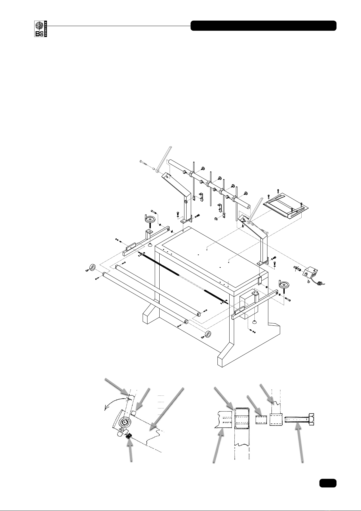
2. Assembling the Blade Rite 1750
2.1 You should receive this machine partly assembled.
2.2 Bolt the two support uprights to the top of the main chassis with the M12 hex bolts
provided. Do not fully tighten at this stage.
2.3 Slide the suspension and stop rod assemblies over the upper support rail.
Bolt the support bar between the support uprights tting the lift over guard at the same
time.
Guard Guard
Spacer
Support Upright
Upper Stop
Adjustable Lower Stop Upper Support Rail M12 Hex Bolt

5
BLADE RITE 1750 MANUAL
© Bernhard and Company Limited
3.1 Setting up for Blade Thinning (Relief grinding)
Note 1: Blade thinning (Relief grinding) is best carried out after the reel has been spun
ground to a perfect cylinder.
Note 2: Occasionally it may be necessary to remove the front roller and/or scraper from
some units to gain better access.
3.2 The mowing unit should sit with it’s rear roller in ‘vee’ support of the mower support
carriage [1] (g. 3.2.1.)
The hook/rope from the ratchet pulley block [2] should be attached to/around a convenient
point on the front of the mowing unit.
Raise the front of the unit whist simultaneously pulling the rope of the pulley block (g.
3.2.1.).
Slide the support carriage forward, complete with mowing unit, and set the unit into a
suitable position for grinding.
Tighten the 8mm Allen screws at the sides of the support carriage.
Rigidly secure the front of the mowing unit with the suspension rods by:
a) bolting directly to a convenient point on the mower frame, or (g.3.2.2.).
b) clamping to a suitable point with the suspension rod clamps.(g 3.2.3.).
1
3. Reel Grinding
Fig. 3.2

6
BLADE RITE 1750 MANUAL
© Bernhard and Company Limited
Note: The mounting system enables a wide range of
movement so that reels of all types and sizes
can be positioned to achieve the desired angle of
relief grind.
3.3 The grinding carriage should now be moved along the guide rails so that the grinding disc
can be adjusted close to the reel blades.
The grinding head can be adjusted up and down by loosening the locking ring [3] and
raising/rotating the head about its rear pivot by turning the adjuster knob [3A].
3. Reel Grinding (Continued)
Fig. 3.2.1
2
1
Fig. 3.2.2
Fig. 3.2.3
3A
3
Fig. 3.3
4
6
5

7
BLADE RITE 1750 MANUAL
© Bernhard and Company Limited
(Cont.) It can be adjusted in and out by means of the feed handwhee [4].
The blade rest (support nger) [5] should be positioned as close to the grinding wheel as
possible, then feed the grinding head in so that one end of one blade is supported by the
rest with the grinding wheel hardly touching the blade (Very light contact).
Traverse the grinding carriage to the other end of the blade, rotating the reel with the other
hand to keep the blade supported on the rest. Contact between blade and grinding wheel
should be even along the blade length. Adjustment to achieve this can be made using the
handwheels on the left and right hand guide rail side arms.
(Generally raising a side arm, turn handwheel clockwise, will bring the blade closer to the
grinding wheel at that end, whilst lowering a side arm, turn handwheel counter clockwise
will have the opposite result).
Note: It may be necessary to re-adjust the position of the mower, to obtain the desired
relationship between grinding wheel and blade, in order to achieve the desired angle of
relief grind, but with experience this positioning becomes quick and easy.
3.4 Set the left-hand traverse stop collar on the guide rail so that the grinding wheel covers
the left-hand end of the reel blade. The reel blade stays on the blade rest whilst the index
nger [6] springs up above the blade ready for traverse towards the right.
3.5 Set the right hand traverse stop collar on the guide rail so that the grinding wheel and
blade rest (support nger just clear the end of the reel blade without coming into contact
with the mower’ side plate or frame). The reel rotates forwards and the next reel blade
pushes the index nger down aligning the blade so that it will run onto the blade rest when
traverse is to the left.
3.6 Adjust the “low” position of the index nger so that it leads the reel blades smoothly onto
the blade rest (support nger) The weight of the reel blade should not be at this index
nger during right to left traverse; Adjust the “high” position so that the index nger is just
clear (above) blades for r/h traverse AND is caught by the next blade when the reel rotates
at the index position (r/h traverse stop); If necessary the index nger can be adjusted in
and out of it’s mounting block (It is locked in place by a small grub screw).
3. Reel Grinding (Continued)
View from Operator Position Support Finger M6 Wing Knob
Index Finger
Support
Finger
Set Index Finger
“High” Position
Set Index Finger
“Low” Position
Support
Finger
Reel control motor
moves reel so
that blade collects
index nger
Index nger is set
‘Low’ position so
that blade is led
smoothly onto
support nger
View from Operator Position
At Left-hand Traverse
Reverse Position:
Index Finger springs up
Index Finger
Roller
(High position)
As grinding head
traverses left to right,
ideal position of index
‘High’ nger leaves a
small clearence above
reel blade
Stone stays on
end of reel blade
Index Finger
Roller
(Low position)
8
BLADE RITE 1750 MANUAL
© Bernhard and Company Limited
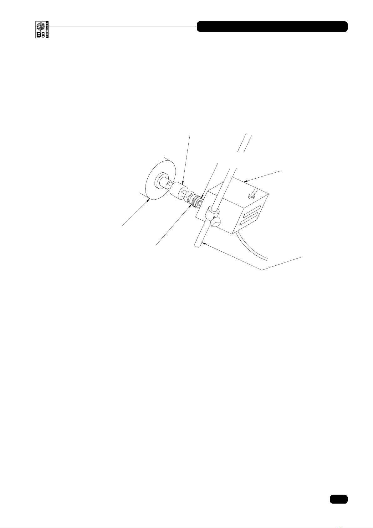
3.7 Connect reel drive motor. Loosen the locking lever clamping the support rod position
and the wing knob that locks the motor to the support rod; Rotate the support rod in it’s
mounting and slide the motor up and down until the output shaft aligns with the reel drive.
Connect the “slip clutch” output to the reel with a suitable coupling.
3.8 Select the direction to drive reel down onto blade rest (down from the top) and switch on
the motor.
3.9 Adjust the “slip clutch” so that it just keeps the reel blades onto the nger so that there is
sufcent torque for a smooth index between blades. This is achieved by loosening the
locking ring and by rotating the adjusting collar at the rear of the “slip clutch” (closest to
motor/gearbox) to increase spring compression; Clockwise rotation increases torque,
counter clockwise rotation reduces it.
3.10 Traverse the grinding head, by hand, to the left and right to check that the indexing is
working (remember to pause at the r/h traverse stop to give the reel time for the next blade
to reach the rest)
3.11 Switch on the traverse motor and engage with the lever, to conrm indexing works (The
traverse automatically pauses at each end, longer at the right-hand end to allow time for
indexing). If all is ok, disengage the traverse. Traverse speed may be adjusted by means of
the potentiometer knob on the control panel.
3.12 Mark one blade as a “datum” so that it can be returned to each time.
3.13 Lower the safety guard.
Note: Before actual grinding takes place, ensure that appropriate safety wear is used (see safety
notes in section 1).
3. Reel Grinding (Continued)
Reel Drive Motor
Reel Cutting Unit
Coupling
Slip Clutch
Torque Adjusting Collar
Suspension Rod

9
BLADE RITE 1750 MANUAL
© Bernhard and Company Limited
4.1 Switch on the grinding motor and apply a light cut. Traverse the length of the blade
manually without touching the l/h stop or allowing the blade to index. Check that the
width/angle of cut is constant along the blade length. Adjust the side arm handwheels, if
necessary, to achieve this.
4.2 Apply a reasonable cut and engage the traverse.
4.3 Increase the feed as necessary to keep the cut on each blade constant.
4.4 Finish the nal rotation of the reel with a light cut so that grindstone wear does not effect
the relative amount of metal removed from each blade.
4.5 Disengage the traverse and switch off vacuum and grinder, traverse and reel drive motors.
4. Relief Grinding (Blade Thinning)

10
BLADE RITE 1750 MANUAL
© Bernhard and Company Limited
5. Parts List
Page
BASE _________________________________________________ 11
CARRIAGE _____________________________________________ 13
MOTOR PLATE AND TRANSMISSION ______________________ 15
ELECTRICAL CABINET __________________________________ 17
CONTROL BOX _________________________________________ 18
GUARD ________________________________________________ 19

11
BLADE RITE 1750 MANUAL
© Bernhard and Company Limited
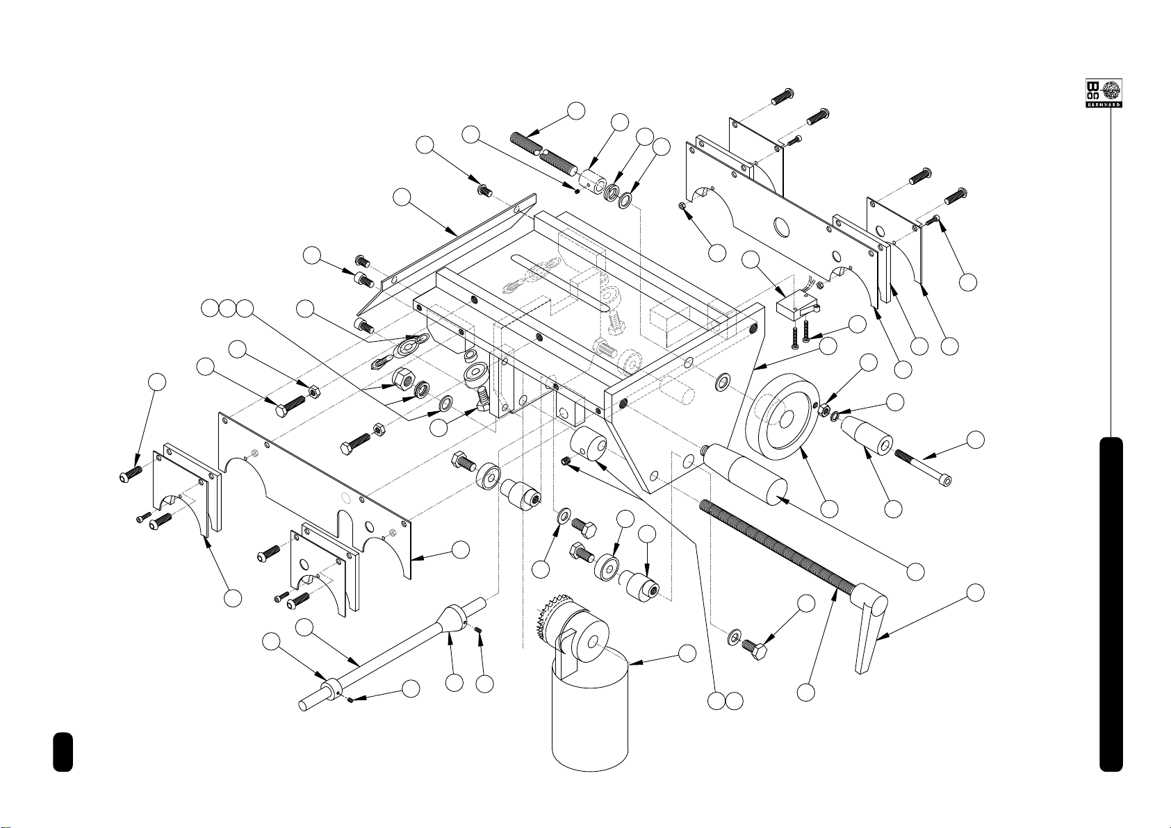
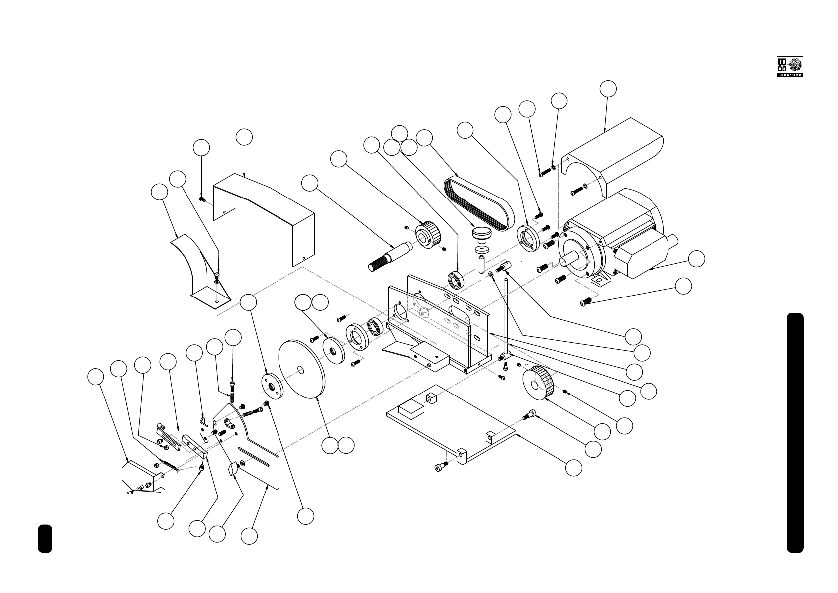
BASE ________________________________________________________________________
1 Base Frame ............................................................................. 1 A4216
2 R.H. Top Rail Support Arm ..................................................... 1 A4232
3 L.H. Top Rail Support Arm ......................................................1 A4233
4 R.H. Sidearm...........................................................................1 A4218
5 L.H. Sidearm ........................................................................... 1 A4219
6 Roller Cradle ...........................................................................1 A4239
7 Suspension Clamp ..................................................................2 A4237
8 Suspension Clamp Cradle ......................................................2 A4238
9 Top Rail ...................................................................................1 A6152
10 Front Rail .................................................................................2 A9134
11 Traverse Collar Stop................................................................ 2 A9136
12 ” Drive for Clutch ..................................................................1 A9140
13 Top Rail Clamp Block (large) .............................................3 (4) A4235
14 Setting Rod/Reel Motor Support....................................... 1 (2)
15 Cylinder Drive Motor ...............................................................1 A6028
16 Clutch ...................................................................................... 1 A9727
17 Handwheel 100 dia .................................................................2 A6148
18 Lobed Knob M8 x 20 ......................................................... 6 (8) A6146
19 Lobed Female Knob M8..........................................................2 A6166
20 Foot 50 dia............................................................................... 2 A6147
21 Wing Knob M6 x 15 .................................................................1 A6129
22 Lobed Knob M8 x 20 ............................................................... 2 A6146
23 Shoulder Screw 16 dia x 40 x M12.......................................... 2 A5178
24 Shoulder Screw 12 dia x 50 x M10.......................................... 4 A5177
25 Hex. Set Screw M12 x 30 ........................................................ 4 A5713
26 Washer M16 ............................................................................4 A6808
27 Cap Head Screw M10 x 20 .....................................................4 A5180
28 Washer M12 ............................................................................4 A5315
29 M16 Double Coil Spring Washer ............................................. 2 A5493
30 Grub Screw M4 x 6.................................................................. 3 A5190
31 Cap Head Screw M10 x 25......................................................1 A5116
32 Washer M10 ............................................................................4 A5310
33 Side Arm Plastic Cap .............................................................. 4 A6150
34 Top Rail Support Arm Plastic Cap ..........................................2 A6153
35 12” Scale (not shown) .............................................................2 A6629
36 Traverse Chain ........................................................................ 1 A7408
37 Chain Tension Bolt ..................................................................2 A5420
38 Chain Link................................................................................ 2 A7502
39 Tension Spring ........................................................................2 A6739
40 Nut M10 ...................................................................................4 A5504
41 Chain Link................................................................................ 2 A7502
42 Tension Spring ........................................................................2 A6739
43 Nut M10 ...................................................................................4 A5504
44 Diamond Dresser (Not shown)................................................1 A6737
9. Parts List (Continued)
Ref # Name of Part Qty. Part #

12
BLADE RITE 1750 MANUAL
© Bernhard and Company Limited
9. Parts List
(Continued)
1
2
3
4
5
6
9
10
11
14
16
17
18
19
20
21
23
24
25
26
28
27
29
30
31
32
34
33
35
36
37
39 40
41
42
43
20
8
15
7
BASE

13
BLADE RITE 1750 MANUAL
© Bernhard and Company Limited
Ref # Name of Part Qty. Part #
CARRIAGE __________________________________________________________________
1 Carriage Base ......................................................................... 1 A4241
2 Carriage Deector Front.......................................................... 1 A6367
3 R.H. Inner Wiper Plate ............................................................ 1 A6368
4 Outer Front Wiper Plate ..........................................................2 A6369
5 Wiper Felt ................................................................................4 A6811
6 Eccentric Adjuster ................................................................... 2 A4223
7 Feedscrew ............................................................................... 1 A9150
8 Feedscrew Locking Bush ........................................................1 A9151
9 Bearing Spacer ....................................................................... 4 A9147
10 Bearing 628zz ......................................................................... 7 A7723
11 Feed Screw Handle 80mm......................................................1 A6154
12 Handle M6 x 20 dia ................................................................. 1
13 Handle M10 x 20 .....................................................................1 A6170
14 Hex Head Bolt M8 x 18 ..........................................................2 A5731
15 Hex Head Bolt M8 x 20 .......................................................... 4 A5726
16 Button Head Screw M6 x 16 .................................................. 8 A5148
17 Button Head Screw M6 x 10 ..................................................2 A5142
18 Brass Hex Set Screw M6 x 25 ................................................2 A5750
19 Brass Full Nut M6....................................................................2 A5528
20 Cap Head Socket Screw M3 x 12 ........................................... 4 A5181
21 Nut M3 ..................................................................................... 4 A5510
22 Cap Head Screw M6 x 60 ....................................................... 1 A5157
23 Washer M8 ..............................................................................2 A5321
24 D’Coil Spring Washer M10 ...................................................... 1 A5309
25 Washer M10 ............................................................................2 A5310
26 Washer M6 ..............................................................................1 A5320
27 Grub Screw M3 x 4.................................................................. 1 A5207
28 Traverse Motor 24v DC ...........................................................1 A3396
29 Cap Head Screw M6 x 12 ....................................................... 2 A5171
30 Microswitch.............................................................................. 1 A8163
31 Slotted Pan Head Screw M3 x 20 .......................................... 2 A5430
32 Traverse Actuator Rod ............................................................ 1 A9148
33 Traverse Actuator Cone .......................................................... 1 A9149
34 Traverse Rod Stop Collar ........................................................ 1 A9163
35 Socket Screw M5 x 6............................................................... 1 A5137
36 Socket Screw M6 x 6............................................................... 1 A5156
37 Clutch Shaft (Long) ................................................................. 1 A3391
38 Clutch Lever M10..................................................................... 1 A6157
39 Clutch Eccentric ...................................................................... 1 A9159
40 Socket Screw M5 x 5............................................................... 1 A5137
41 Washer M10 ............................................................................1 A5310
42 D’Coil Spring Washer M10 ...................................................... 1 A5309
43 Nyloc Nut M10 ......................................................................... 1 A5505
44 Outer Rear Wiper Plate ........................................................... 2 A6370
45 L.H. Inner Wiper Plate.............................................................1 A6371
46 Nut M6 ..................................................................................... 1 A5516
47 Traverse Motor Bracket/Adaptor Plate (Not shown) ............... 1 A3394
9. Parts List (Continued)
14
BLADE RITE 1750 MANUAL
© Bernhard and Company Limited
12
43 42 41
40
39
38
37
36 35
34
33
32
31
30
29
28
15
23
6
10
14
13
11
22
5 4
3
26
1
21
25
24
8
7
27
17
2
9
19
18
20
16
BR1750 CARRIAGE
46
44
45
9. Parts List
(Continued)

15
BLADE RITE 1750 MANUAL
© Bernhard and Company Limited
MOTOR PLATE AND TRANSMISSION __________________________________
1 90 Degree Rotating Base........................................................1 A4245
2 Motor Transmission Housing................................................... 1 A4147
3 Index Mounting Plate............................................................... 1 A4151
4 Index Finger Block................................................................... 1 A4152
5 Index Finger c/w Roller ........................................................... 1 A3397
6 Blade Rest ............................................................................... 1 A4154
7 Cover for Index Mechanism .................................................... 1 A6373
8 Pin Lock Plate ......................................................................... 2
9 Stone Guard ............................................................................1 A6374
10 Stone Spacer for 6mm Stone..................................................1 A3387
10A Stone Spacer for 9.5mm Stone...............................................1 A3386
11 Grinding Wheel Spindle .......................................................... 1 A9152
12 Lobed Knob .............................................................................1
12A Locking Ring............................................................................ 1
12B Spacer .....................................................................................1
13 Bearing Housing......................................................................2 A9153
14 30 tooth Pulley 60Hz (Driven) ................................................. 1 A7214
15 40 toothed Pulley (Drive) ........................................................1 A7210
16 Drive Belt 5mm x 16mm x 420mm ..........................................1 A7108
17 Bearing 6003 2RS................................................................... 2 A7726
18 Main Motor 60Hz single phase ...............................................1 A6006
Main Motor 50Hz single phase ...............................................1 A6004
Main Motor 50 / 60Hz 3 phase................................................1 A6005
19 Motor Cover Plate ...................................................................1 A6446
20 125 x 6mm Stone ....................................................................1 A3382
20A 125 x 9.5mm Stone ................................................................. 1 A3383
21 Shoulder Screw M8 x M6 x 12 ................................................ 3 A5165
22 Upper Height Adjust Boss .......................................................1 A3393
23 Wing Knob M6 x 15 .................................................................1 A6129
24 Height Adjust Stud................................................................... 1 A3390
25 Lower Height Adjust Stud........................................................1 A3389
26 Button Head Screw M5 x 25 ...................................................2 A5169
27 Button Head Screw M5 x 16 ...................................................6 A5133
28 Button Head Screw M8 x 16 ...................................................4 A5813
29 Cap Head Socket Screw M6 x 12 ........................................... 2 A5171
30 Cap Head Socket Screw M5 x 6 ............................................. 4 A5139
31 Nylock Nut M5 .........................................................................2 A5513
32 Index Finger Spring .................................................................1 A6814
33 Spring .....................................................................................2 A6908
34 Button Head Screw M5 x 6 .....................................................2 A5139
35 Socket Grub Screw M4 x 6 .....................................................4 A5190
36 Washer M6 ..............................................................................2 A5320
37 Washer M5 ..............................................................................3 A5318
38 Button Head Screw M5 x 10 ...................................................1 A5129
39 Transmission Cover Guard .....................................................1 A6372
40 Button Head Screw M3 x 10 ...................................................2 A5187
Junction Box Assembly (Not shown) ...................................... 1 A3403
9. Parts List (Continued)
Ref # Name of Part Qty. Part #
16
BLADE RITE 1750 MANUAL
© Bernhard and Company Limited
2
3
4
56
7
8
11
12 13
14
15
16
17
18
19
20 21
22
23
25
26
27
28
29
30
31 32
33
34
35
36
37
38
40
1
24
39
MOTOR PLATE
& TRANSMISSION
12A 12B
20A
9
10 10A
9. Parts List (Continued)
17
BLADE RITE 1750 MANUAL
© Bernhard and Company Limited
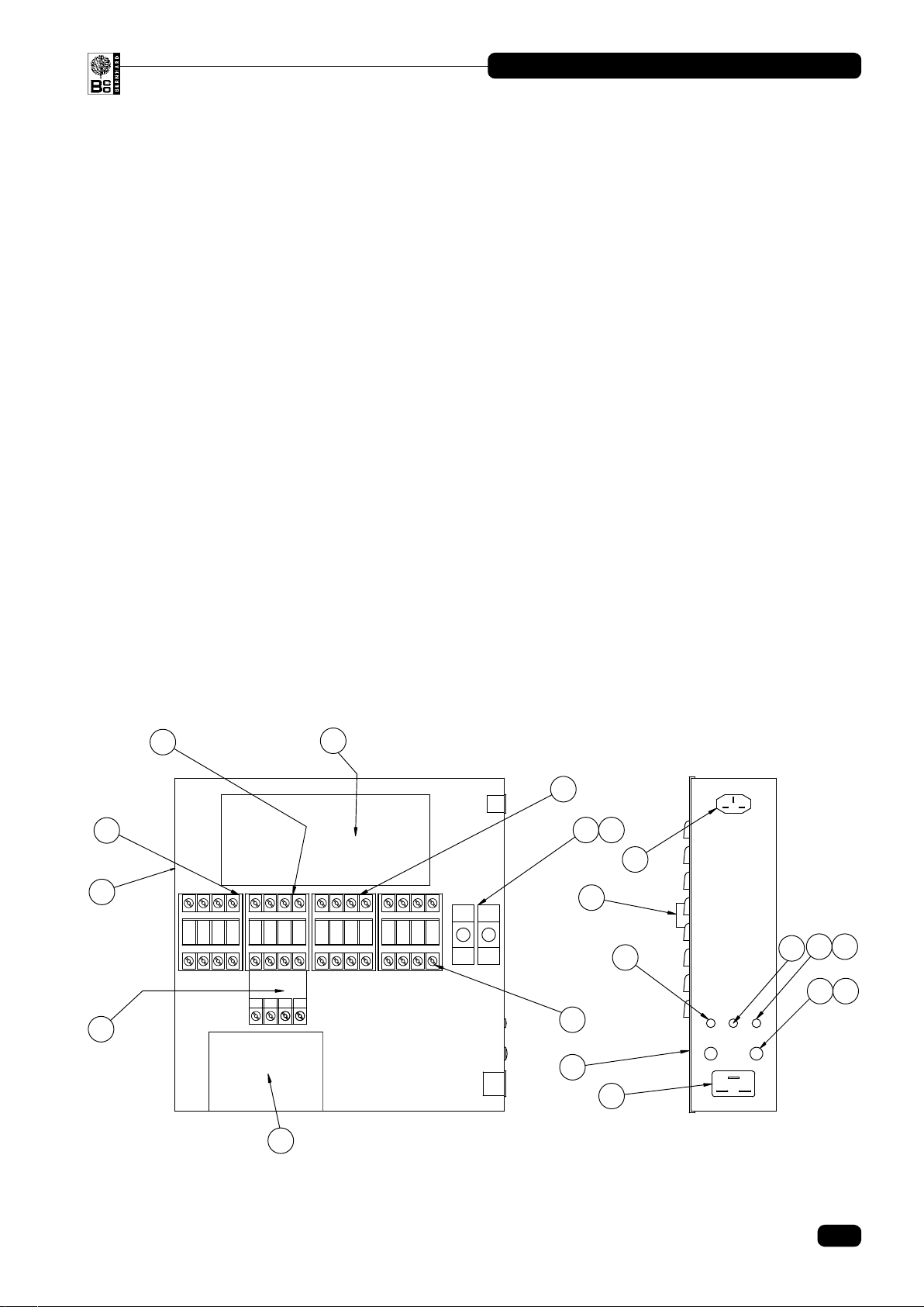
ELECTRICAL CABINET ___________________________________________________
1 Electrical Box .......................................................................... 1 A6379
2 Cover .......................................................................................1
3 Main Motor Contactor..............................................................1 A8063
4 Thermal Overload ...................................................................1 A8116
5 Traverse Motor Contactor .......................................................1 A8063
6 Reversing Contactor ............................................................... 1 A8062
7 Reel Drive Motor Contactor ....................................................1 A8063
8 Transformer 24v ......................................................................1 A8928
9 Timer Base ....................................................................... 1 (2) A8176
10 Timer ................................................................................. 1 (2) A8175
11 10 amp 3 pin Plug.................................................................... 1 A8172
12 10 amp 3 pin Socket................................................................ 1 A8171
13 Control/Traverse Fuse 2 amp .................................................1 A8085
14 Fuse Holder ............................................................................. 2 A8173
15 Transformer Fuse 5 amp ......................................................... 1 A8086
16 Mains Supply Fuse 10 amp.....................................................2 A8083
17 Fuse Holder ............................................................................. 2 A8174
18 Reset Button............................................................................ 1 A8130
19 Reel Control with Motor Fuse 2 amp....................................... 1 A8085
20 DC Control Card (Traverse Motor)..........................................1 A8187
Ref # Name of Part Qty. Part #
9. Parts List (Continued)
1
2
4
5
6
7
8
9 10
11
13 14
15
16 17
18
19
IMO
TY4
SIDE VIEW
INTERNAL VIEW OF ELECTRICAL CABINET
3
12
ELECTRICAL CABINET
TY4
IMO
20
18
BLADE RITE 1750 MANUAL
© Bernhard and Company Limited
Ref # Name of Part Qty. Part #
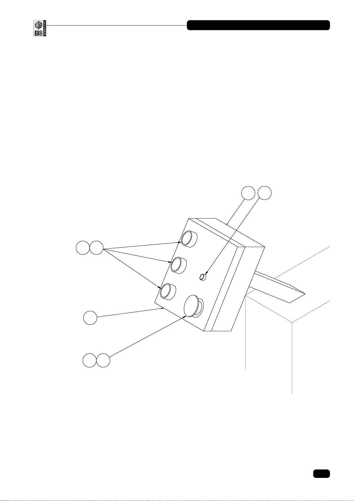
CONTROL BOX ____________________________________________________________
1 Control Box.............................................................................. 1 A6452
2 Control Box Lid........................................................................1 A6454
3 Emergency Stop......................................................................1 A8073
4 Push Button.............................................................................3 A8040
5 Contact Block N/O .................................................................. 3 A8235
6 Contact Block N/C...................................................................1 A8236
7 Traverse Speed Potentiometer ...............................................1
9. Parts List (Continued)
1
2
3
4
CONTROL BOX
5
6
7
19
BLADE RITE 1750 MANUAL
© Bernhard and Company Limited
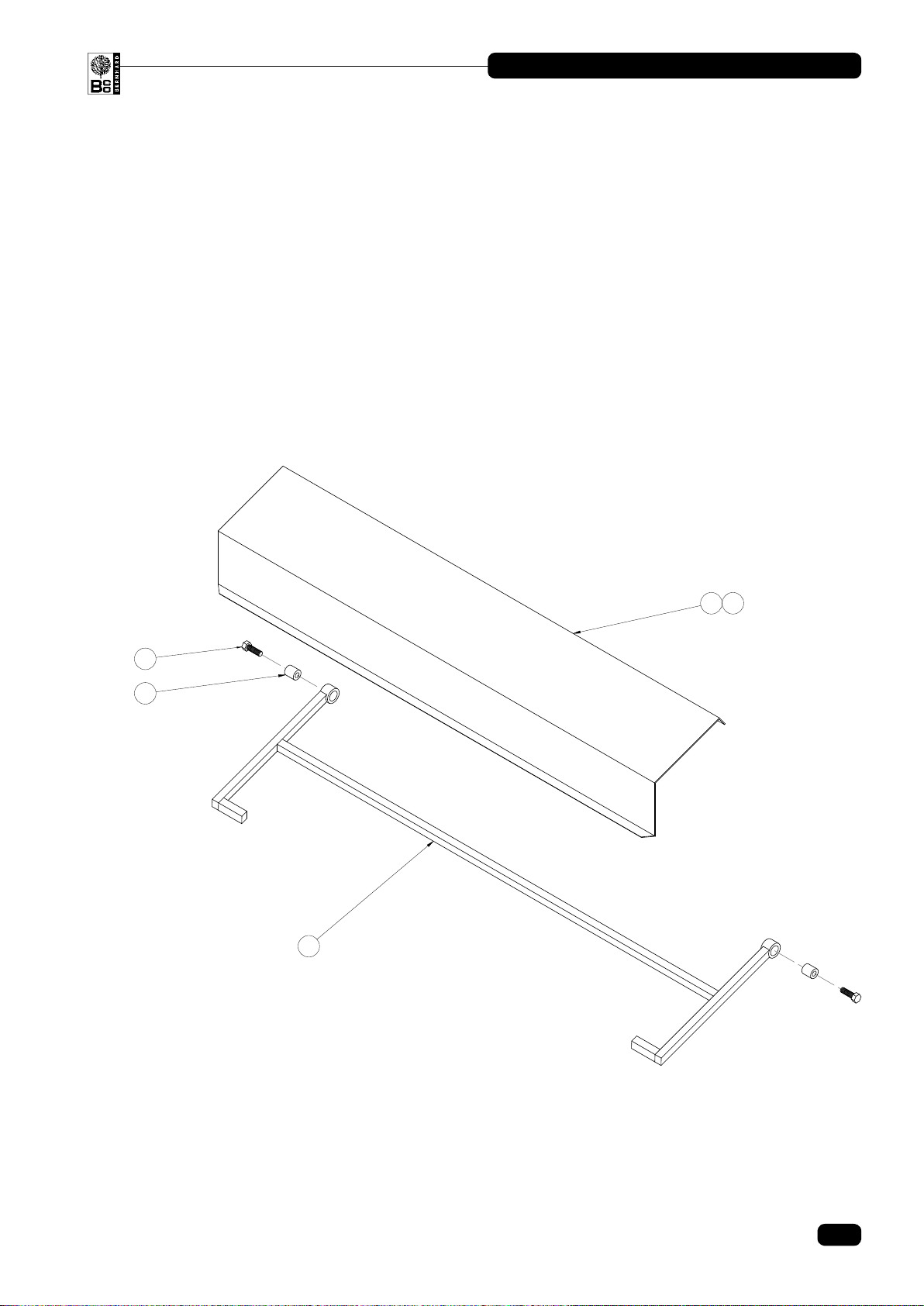
GUARD ______________________________________________________________________
1 Main Frame .............................................................................1 A4234
2 Makralon Guard ...................................................................... 1 A6800
3 Plastic Rivets...........................................................................7 A5427
4 Hex Head Bolt M12 x 40.......................................................... 2 A5728
5 Guard Spacer / Bush...............................................................2 A9142
Ref # Name of Part Qty. Part #
9. Parts List (Continued)

BERNHARD AND COMPANY LTD / ATTERTON AND ELLIS LTD
Declare that the product:
Machine Name
Type
Serial No.
To which this declaration relates complies with the relevant Health &
Safety requirements of EC Directive:
89/392/EEC
as amended by:
91/368/EEC
93/44/EEC
93/68/EEC
and that for the implementation of the Health & Safety requirements the
following standards and/or technical specifications have been
consulted:-
ISO 7000 1989
BS.EN 292 Pt. 1 1991
BS.EN 292 Pt. 2 1991
BS.EN 418 1992
Stephen Bernhard (Managing Director)
Date:
BERNHARD AND COMPANY LIMITED • BILTON ROAD • RUGBY • ENGLAND CV22 7DT
EC DECLARATION OF CONFORMITY
Table of contents
Other Bernhard Grinder manuals


Popular Grinder manuals by other brands


EINHELL Bavaria
EINHELL Bavaria BWS 115/850-2 operating instructions

Maktec
Maktec GD0600 instruction manual

Toolla
Toolla TM 76010 instruction manual

Bosch
Bosch GBG 35-15 Professional Original instructions

BGS technic
BGS technic BGS 3290 instruction manual

EINHELL
EINHELL TP-AG 1212 E operating instructions


